Bosch AEC-AMC2-UL01 User manual

AMC2 enclosure with 1 DIN rail
AEC‑AMC2‑UL01
en Installation manual


AMC2 enclosure with 1
DIN rail Table of contents | en 3
Bosch Security Systems B.V. 2020-07 | V04 | F.01U.330.018
Table of contents
1System overview 4
1.1 Components of the enclosure 4
1.2 Parts included 6
1.3 Cables to be assembled 8
2Mounting the enclosure 10
3Connections 11
3.1 Connecting the devices 11
3.2 Connecting the cables 13
3.3 Connections for supporting Universal Power Supply 15
3.3.1 12 V mode operation 16
3.3.2 24 V mode operation 18
4Appendices 20
4.1 UL requirements 20
4.2 Cable assembly 21

4en | System overview AMC2 enclosure with 1
DIN rail
2020-07 | V04 | F.01U.330.018 Bosch Security Systems B.V.
1 System overview
1.1 Components of the enclosure
1 2 3 4
6
78
11
12
13
9
5
10
Figure1.1: Components of the enclosure
Position Description
1 Cover grounding point
2 Mounting rail for power supply unit (PSU) and
Access Modular Controller (AMC2)
3 AMC2 grounding point
4 Cable knock-outs for reader and signal cables
5 Temperature sensor bracket
6 Tamper contact
7 Fixing bracket for rechargeable batteries
8 Main grounding point

AMC2 enclosure with 1
DIN rail System overview | en 5
Bosch Security Systems B.V. 2020-07 | V04 | F.01U.330.018
Position Description
9 Label
10 Knock-out for the power cable connection
11 Three pin connector
12 Bracket for LED
13 Name plate

6en | System overview AMC2 enclosure with 1
DIN rail
2020-07 | V04 | F.01U.330.018 Bosch Security Systems B.V.
1.2 Parts included
x3 x1
x1
x1
x2A
B
E
C
D
x1
F

AMC2 enclosure with 1
DIN rail System overview | en 7
Bosch Security Systems B.V. 2020-07 | V04 | F.01U.330.018
Position Description
A Cable ties to secure cables
B Three screw anchors S8 and M6 × 50 screws
C Bracket for cable fixing
D Fuse and fuse holder
E LED
F Cover grounding cable

8en | System overview AMC2 enclosure with 1
DIN rail
2020-07 | V04 | F.01U.330.018 Bosch Security Systems B.V.
1.3 Cables to be assembled
D
A
C
B
E
F
Position Description
A Power supply cable (AMC2)
B Power supply cable (battery)
C Battery cable
D Cover contact wired
E Power cable

10 en | Mounting the enclosure AMC2 enclosure with 1
DIN rail
2020-07 | V04 | F.01U.330.018 Bosch Security Systems B.V.
2 Mounting the enclosure
The enclosure is designed to be mounted on a wall.
1. Open the door lock of the enclosure with the provided key.
2. Hold the enclosure at the desired position against the wall.
3. Mark the mounting holes on the wall with a pencil.
4. Put the enclosure aside.
5. Drill the holes at the points that you previously marked on
the wall.
6. Insert the screw anchors in the drilled holes.
7. Drive the screws halfway into the top and bottom left screw
anchors.
8. Hang the enclosure on the wall, according to the position of
the screw anchors.
9. Drive the third screw into the anchor on the bottom right.
10. Tighten all screws.
– The enclosure is installed.
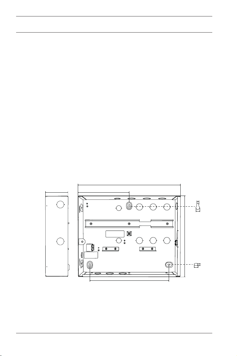
86,5 mm
3,406 in
401 mm
15,787 in
352,5 mm
13,878 in
5 mm
0,197 in
318 mm
12,52 in
10 mm
0,394 in
5 mm
0,197 in
10 mm
0,394 in
200,5 mm
7,894 in
Figure2.1: Dimensions of the enclosure

AMC2 enclosure with 1
DIN rail Connections | en 11
Bosch Security Systems B.V. 2020-07 | V04 | F.01U.330.018
3 Connections
3.1 Connecting the devices
Precondition: Install readers and other peripheral devices as
described in the corresponding technical documentation.
AC
N G L1
BAT RTH
Power Supply
AMC2
DC
RS-485 EXT T
---- OK ----
L N + - + - + -C DC BAT AC 1 2 3 4 5 6 7
1 2 3 4 5 6 1 2
2
1
Figure3.1: Connections in the enclosure
1. Insert the cables of the device through the knock-outs at
the top-right side wall of the enclosure, or through the rear
of the enclosure.
2. Provide an appropriate disconnect device to the supply
line.
!
Warning!
Risk of electric shock!
Disconnect the mains supply voltage before you work on the
devices inside the enclosure.

12 en | Connections AMC2 enclosure with 1
DIN rail
2020-07 | V04 | F.01U.330.018 Bosch Security Systems B.V.
Installing the components
1. Mount the Access Modular Controller (AMC2) on the right-
hand side of the mounting rail.
2. Mount the power supply unit on the left-hand side of the
mounting rail.
3. If you are using rechargeable batteries, install the batteries
at the bottom of the enclosure and secure them with a
fixing bracket.

AMC2 enclosure with 1
DIN rail Connections | en 13
Bosch Security Systems B.V. 2020-07 | V04 | F.01U.330.018
3.2 Connecting the cables
Notice!
See chapter
Cable assembly, page 21
for a list of UL
approved/listed cables and UL authorized suppliers.
Connecting the AMC2 power cable (A)
1. Connect the 7-pin plug A7 (Figure 4.1) to the power supply
connector (label: POWER) of the AMC2.
2. Attach connector A8 (Figure 4.1) to the power supply
connection labeled OK.
3. Attach connector A9 (Figure 4.1) to the power supply
connection DC.
4. Connect the grounding cable A6 (Figure 4.1) to the AMC2
grounding point.
Connecting the AC power cable (F)
1. Use the cables to connect the three-pin connector (Figure
1.1, position 11) to the AC connector (Figure 4.6, position
F4) of the power supply.
2. Connect the blue wire to the port marked with N (Figure
3.2, positions 2 and 4).
3. Connect the brown wire to the port marked with L (Figure
3.2, positions 1 and 3).
AC
N G
L1
BAT RTH
L N + -
Figure3.2: Connections of the LED indicator

14 en | Connections AMC2 enclosure with 1
DIN rail
2020-07 | V04 | F.01U.330.018 Bosch Security Systems B.V.
Mounting and connecting the power cable with LED indicator
(G)
Notice!
Use this cable (G) instead of cable F if you are installing a
system that is to be UL approved.
1. Pass the cable end through the front of the LED bracket
hole (Figure 1, position 12).
2. Carefully pull the cable through the back of the LED
bracket.
3. Make sure that the LED reaches and fits the LED bracket
hole.
4. Connect the single brown wire to position 3, marked with L
(Figure 3.2).
5. Connect the other end from the brown wire to position 1,
marked with L1 (Figure 3.2).
6. Connect the single blue wire to the position 4, marked with N
(Figure 3.2).
7. Connect the other end from the blue wire to the position 2,
marked with N ( Figure 3.2).
Connecting the tamper contact (E)
1. Mount the micro switch with two screws M2 x 10 mm
(Figure 1.1, position 6) at the right side of the enclosure.
2. Connect the loose ends of the tamper contact cable to the
two-pin screw connector (marked with T) at the top of the
AMC2.
3. Position the cable in the space between the housing and
the mounting rail.
Danger!
Risk of electric shock
Make sure that all wires have zero potential.

AMC2 enclosure with 1
DIN rail Connections | en 15
Bosch Security Systems B.V. 2020-07 | V04 | F.01U.330.018
Connecting the main AC supply X
1. Connect the ground cable to the main grounding point
(Figure 1.1, position 8).
2. Connect the neutral wire to terminal N (Figure 3.2).
3. Connect the phase wire to terminal L1 (Figure 3.2).
4. Shorten the external supply wires so that the ground wire
is a minimum of 20 mm longer than the live wires.
– This will prevent the ground wire from being
accidentally disconnected.
Connecting the cover grounding cable
1. Connect the mounted grounding cable (see position F of
Parts included, page 6
) to the cover grounding point
(Figure 1.1, position 1) and to the grounding point on the
cover of the enclosure.
2. Make sure that the screws of the two earthing points are
sufficiently tightened.
Refer to
– Parts included, page 6
– Cable assembly, page 21
3.3 Connections for supporting Universal
Power Supply
Precondition: Before switching to battery operation, disconnect
the AC power cable.
Notice!
Use 12V 7 (7,2)Ah lead batteries only.
Notice!
Change the lead batteries every 5 years.

16 en | Connections AMC2 enclosure with 1
DIN rail
2020-07 | V04 | F.01U.330.018 Bosch Security Systems B.V.
3.3.1 12 V mode operation
Notice!
Make sure that the power supply has the correct output voltage
(12V).
+ -
B12
B7a
B8a
B7b B8b
+ - + -
B12
B7a B7b B8a B8b
Figure3.3: 12V mode with one battery (left); 12 V mode with two batteries
(right)
12V mode operation using one battery
1. Set the switch of the power supply unit to 12V.
2. Connect B12 to the power supply interface labeled BAT.
3. Connect B7b (black) to the rechargeable negative (-)
terminal of the battery.
4. Connect B7a (red) to the rechargeable positive (+) terminal
of the battery.
5. Attach the bracket to the back of the housing next to the
batteries.
6. Attach the connectors B8a and B8b to the bracket.

AMC2 enclosure with 1
DIN rail Connections | en 17
Bosch Security Systems B.V. 2020-07 | V04 | F.01U.330.018
12 V mode operation using two batteries
1. Set the switch of the power supply unit to 12V.
2. Connect B12 to the power supply interface labeled BAT.
3. Connect B7b (black) to the rechargeable negative (-)
terminal of the battery.
4. Connect B7a (red) to the rechargeable positive (+) terminal
of the battery.
5. Connect B8b (black) to the second rechargeable negative
(-) terminal.
6. Connect B8a (red) to the second rechargeable positive (+)
terminal of the battery.

18 en | Connections AMC2 enclosure with 1
DIN rail
2020-07 | V04 | F.01U.330.018 Bosch Security Systems B.V.
3.3.2 24V mode operation
Notice!
Make sure that the power supply has the correct output voltage
(24V).
+ - + -
B12
C1
B7a B7b
Figure3.4: 24V mode
Connecting the battery cables
1. Set the switch of the power supply unit to 24V.
2. Connect B12 to the power supply interface labeled BAT.
3. Connect B7a (red) to the positive (+) pin of the first
rechargeable battery.
4. Connect B7b to the negative (-) pin of the second
rechargeable battery.
5. With cable C1 (black), connect the negative (-) pin of the
first rechargeable battery to the positive (+) pin of the
second rechargeable battery.
6. Attach the connectors B8a and B8b to the bracket.

AMC2 enclosure with 1
DIN rail Connections | en 19
Bosch Security Systems B.V. 2020-07 | V04 | F.01U.330.018
7. Attach the bracket to the back of the housing next to the
batteries.

20 en | Appendices AMC2 enclosure with 1
DIN rail
2020-07 | V04 | F.01U.330.018 Bosch Security Systems B.V.
4 Appendices
4.1 UL requirements
Notice!
All cables connected to the AMC2 modules and the power
supply are classified as Class 2 conductors. The battery cable
and the AC input cable are non-power limited circuits.
Notice!
Maintain a minimum of 6.4 mm spacing between all class 2 or 3
conductors and all electric, light, power, Class 1 conductors,
non-Class 2 or 3 signaling conductors, or medium-power
network-powered broadband communications-circuit
conductors (Figure 3.1, position 1 and 2).
Notice!
When the fuse (5A) of cable B (power supply battery) is blown,
replace it with a UL listed fuse and reseal the fuse holder with a
heat shrink tube.
Notice!
If the system is to be UL294 compliant, make sure that all the
cables and the respective parts are UL listed or approved.
Notice!
All supplier examples given in chapter
Cable assembly, page
21
are UL authorized.
Table of contents
Other Bosch Enclosure manuals

Bosch
Bosch DSA E-Series (E2700) User manual

Bosch
Bosch AE20 User manual

Bosch
Bosch HCP 0006 A User manual

Bosch
Bosch D8108A User manual

Bosch
Bosch AMC2 Series User manual

Bosch
Bosch D203 Operating and maintenance instructions

Bosch
Bosch B8103 User manual

Bosch
Bosch B10R User manual

Bosch
Bosch FAS-420-TM-HB User manual

Bosch
Bosch FPA-5000 User manual