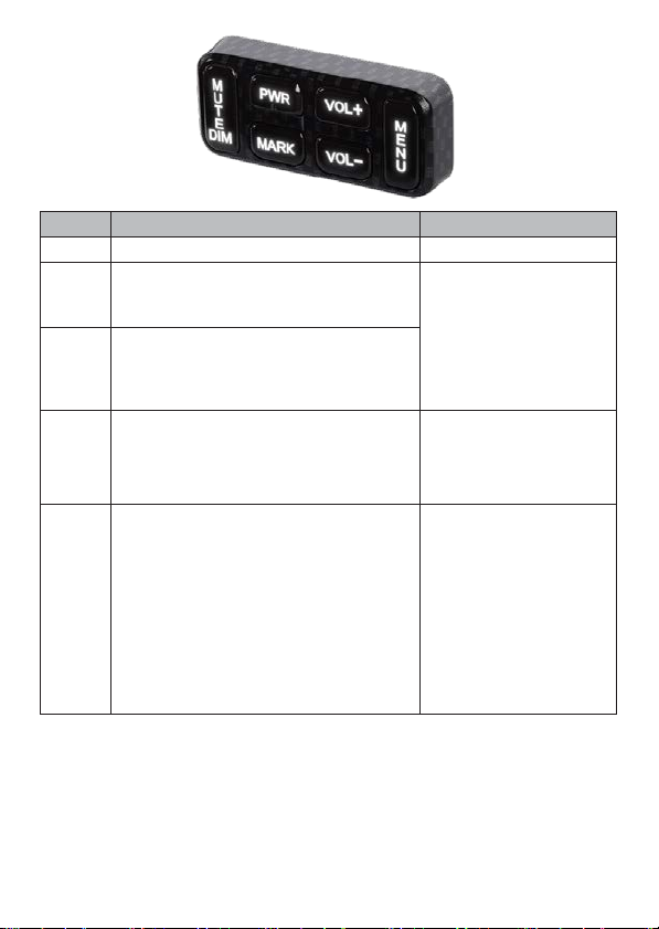
Uniden R9 User manual

360˚ Maximum Protection
R9
Owner’s Manual
© 2020 Uniden America Corporation
Irving, Texas
Issue 1, May 2020
Printed in Korea

CUSTOMER CARE
At Uniden®, we care about you!
Ifyouneed assistance, pleasedoNOT return this product to your placeof purchase
Save your receipt/proof of purchase for warranty.
Quickly find answers to your questions by:
•
Reading this User’s Manual.
•
Visiting our customer support website at www.uniden.com.
Images in this manual may differ slightly from your actual product.
DISCLAIMER: Radar detectors are illegal in some states. Some states prohibit
mounting anyobject on yourwindshield. Check applicable law in your state and
anystatein which you use the product toverify that using and mounting a radar
detectorislegal.Unidenradardetectorsarenotmanufacturedand/orsoldwiththe
intent to be used for illegal purposes. Drive safely and exercise caution while using
this product. Do not change settings of the product while driving. Uniden expects
consumer’s use of these products to be in compliance with all local, state, and
federal law. Uniden expressly disclaimsany liability arising outof or related to your
useofthisproduct.

CONTENTS
CUSTOMER CARE ..................................................................................2
R9 OVERVIEW
.................................................................................... 4
WHAT’S IN THE BOXES?
..........................................................................
4
PARTS OF THE R9
....................................................................................
7
KEYPAD................................................................................................ 7
DISPLAY UNIT .....................................................................................10
R9 INSTALLATION OVERVIEW
...............................................................
11
MENU SYSTEM
.......................................................................................
13
BASIC OPERATIONS
...............................................................................
13
MAINTENANCE
......................................................................................
1
5
MAINTAINING THE EQUIPMENT ..........................................................15
UPDATING THE FIRMWARE/DATABASE ............................................... 15
UPDATE FIRMWARE
..............................................................................
1
5
TROUBLESHOOTING
..............................................................................
1
6
FCC/IC COMPLIANCE
......................................................................... 17
FCC COMPLIANCE ...............................................................................17
IC COMPLIANCE ..................................................................................17
ONE-YEAR LIMITED WARRANTY
...........................................................
1
8

- 4 -
UNIDEN
R9
LONG RANGE RADAR/LASER DETECTOR
USER’S MANUAL
R9 OVERVIEW
Uniden’s R9 is an advanced installed laser radar detector with actual laser
interruption capability. It provides outstanding detection range and usability.
WHAT’S IN THE BOXES?
The R9 packup consists of three boxes.
NOTE: Each box contains packets of screws and other assorted hardware and are
not called out specifically in the following tables.
Box 1 contains:
What it is What it looks like What it does
Controller
ProvidespowertotheR9elements.
Color coded tabs indicate where
each element connects to the
Controller.
Keypad
Control the menu as well as adjusts
andmutesvolumeandalarms,user
marks, and backlight.
Display
Provides the visual display for
alarms, alerts, frequencies, and
menuselections.LEDsontheright
side indicate the signal direction.
GPS
Tracks vehicle location related to
GPSdatabaseforredlightcameras,
speed cameras, etc.

- 5 -
What it is What it looks like What it does
Speaker
Provides audio output for alarms
and alerts, etc.
Active Alert
LED
Incoming signal indicator. (Red =
signal coming from front; Blue =
signal coming from rear; Green
= all clear). Usually mounted in
speedometer area or area within
lineofsight.LEDmountingbracket
is already installed.
Radio Mute
Cable
Mutes the radiowhen analarm or
alert sounds.
Display Bezel
Provides protection to the Display
when installed.
Double-Sided
Adhesive
Tapes
Adheres equipment and cabling to
surfaces.
USB Memory
Stick
Contains Owner’s Manual. Also
used to transfer firmware updates
from website to R9.
Box 2 contains:
What it is What it looks like What it does
Front Remote
Radar
Radar Detector
Adjustable
Mounting
Clamps (2)
The clamps mount on the side of
theRemoteRadarandconnectthe
RemoteRadartothevehicle.

- 6 -
What it is What it looks like What it does
Mounting
Bracket and
Screws for
Remote Radar
Multiple brackets and screws
tomountfrontRemoteRadar
according to different vehicle
configurations.
Laser
Distribution
Box
Connects transponders to main
interface.
Hex wrench
Usewithvariousscrews for
installation.
Transponder
(2)
Detects specific laser signals.
Double-Sided
Adhesive
Tapes
Adheres equipment and cabling to
surfaces.
Cable Ties
Ties loose cables together.
Bubble Level
Levels the transponder interfaces
and remote radars during
installation.
Box 3 contains:
What it is What it looks like What it does
Rear Remote
Radar
Radar Detector

- 7 -
What it is What it looks like What it does
Mounting
Bracket and
Screws for
Remote Radar
Multiple brackets and screws
to mount rear Remote Radar
according to different vehicle
configurations.
Transponder
Interfaces (2)
Detects specific laser signals.
Double-Sided
Adhesive
Tapes
Adheres equipment and cabling to
surfaces.
Cable Ties
Ties loose cables together.
Extension
Cables for
Remote and
Transponder
(3)
Providesextracablelengthif
needed.
Adjustable
Mounting
Clamps (2)
The clamps mount on the side of
theRemoteRadarandconnectthe
RemoteRadartothevehicle.
PARTS OF THE R9
Thissection describes only theR9 parts that are user-accessible. It does notdiscuss
anypartsinstalled outsideofthevehiclecabin.
KEYPAD
The keypad should be installed within the driver’s reach but not high on the
dashboard.The keys onthe keypadcontrol themenu aswell asadjusts the volume,
alarms, user marks, and backlight.

- 8 -
KEY
PRESS TO...
PRESS AND HOLD TO ...
PWR
Turn R9 on.
Turn R9 off.
VOL +
Turn volume up (9levels: 0 - 8; Default = 4).
Thereisonebeepanda volumeupdisplay.
In Menus, go to next item.
NA
VOL –
Turn volume down (9 levels: 0- 8; Default
=4).Thereisonebeepanda volumedown
display.
In Menus, go to previous item.
MENU
Access the Menu system.
InMenus,presstocyclethroughoptions
forthecurrentmenuitem.
When in standby mode,
changes modes between
Highway, City, Auto City
and Advanced.
MARK
User Mark. A User Mark is a manually
tagged geographic location where an
alarmis usually found. TheR9 alertswhen
closetotheseUserMarks.
Add - Press MARK when you are at the
alarm location.
Delete - Press MARK when you are at an
alarm location that has been marked.
An error message displays/sounds if
memory is full or there is a GPS error.
DeleteallUserMarks
(press and hold for 3
seconds).

- 9 -
KEY
PRESS TO...
PRESS AND HOLD TO ...
MUTE/
DIM
•
Turn MUTE onand off.
•
MUTE on - Press MUTE/DIM to mute
radar, laser, red-light cameras, and
overspeedalarms. Returnstonormal
operation 10 seconds after the alert
endsor ifa differentband is detected
duringMutemode. Mute Ondisplays
forafewseconds.
•
MUTE off - Press MUTE/DIM to restore
audible alarms before the 10 second
automatic mute time-out.
MUTE MEMORY
SaveaMuteLocation(Mute Memory)-
pressMUTE/DIM again while Mute On
displays to save that GPS location and
frequency to memory. Mute Memory
displays on the screen.
NOTE: R9 stores 2000 points divided
between Mute Memory and User
Mark locations.
Delete Mute Memory - Press MUTE/
DIM while Mute Memorydisplays; the R9
displaysadelete confirmationmessage.
PressMUTE/DIM again to confirm.
MUTE RED LIGHT CAMERA VOICE ALERTS
Mute thevoice alert for a red light camera
alarm. Press MUTE/DIM while the voice
alarm for a red light camera sounds. The
voice alarm mutes.
MUTE ALERTS FOR POI OVERSPEED ALERT
AND USER LIMIT SPEED
When R9 alerts you to an overspeed or
speedlimitsituation(analarmsoundsand
an alert displays), press MUTE/DIM to
silence that alarm.
DIM-Changesthedisplay
brightness:
•
Auto (Default). Set
brightness levels for the
OLED display (see page
22).
•
Bright
•
Dim
•
Dimmer
•
Dark(Dark is off unless
thereisalert.)
•
Off (Off regardless of
whether or not thereis
an alert.)
DELETE RED-LIGHT
CAMERA POINT
During a red-light camera
alert, press and hold
MUTE/DIM to delete the
red light camera point.
A confirmation message
displays.
After confirming this
deletion, R9 will not give
an alert for that camera.

- 10 -
DISPLAY UNIT
Theseparatedisplayunit installed inthedashboard is thevisualdisplayforalarms,
alerts, and menu selections. Italso displays from which direction the signals are
coming.
Light
Sensor
Signal Direction
Front
Side
Rear
NOTE: If GPS = ON, the OLED’s left display area shows the display selected in the menus.
If GPS = Off, the OLED’s left display area shows Volt regardless of user settings.
The following table provides examples of the most common displays.
OLED EXAMPLES
MEANING
Scanning for Frequencies
Displays to indicate
end of a scan cycle.
42 Hwy
mph
Information displayed in example:
•
Current speed in mph/km/h.
•
Highway/City/Auto City/Advanced
•
Scanning line
Frequency Found
K 24.158
24.158 K
Information displayed:
•
Band Type(X, K, KA,MRCD, Gatso RT3/4)
•
Frequency number
•
Band direction
•
Frequency strength indicators
Speed Camera Alert
Information displayed:
5 8 270 ft
•
Current speed in mph/km/h.
mph
S p e e d
•
Distance to speed camera
•
Speed camera icon
Red Light Camera Alert
Information displayed:
5 8
270 ft
mph
•
Current speed in mph/km/h
•
Distancetoredlightcamera
•
Redlightcameraicon

- 11 -
OLED EXAMPLES
MEANING
User Mark Detected
Information displayed:
5 8
1090 ft
mph
•
Current speed in mph/km/h
•
Distancetousermark
•
Usermarkicon
Time Display
12.8 A 11:45 Hwy
M
Volt
Information displayed:
•
Voltage
•
Time and AM/PM
•
Highway/City/Advanced
RedLightCamera-QuietRide
Information displayed:
5 8 920ft
Mph
•
Current speed in mph/km/h
•
Distancetoredlightcamera
•
Redlightcameraicon
Dark Mode
Set mode to Dark if the unit’s OLED is not
anticipatedtochangealottoprevent image
burn-in (Auto Dim setting).
In Dark mode, the OLED is dark with a single
white dot in the lower corner that moves from
bottom left to center to bottom right. The
movement of the dot confirms that the unit is
still powered up.
R9 INSTALLATION OVERVIEW
This installation overview is a general look at the R9 elements and how they work
together. Where these elements are physically installed can vary from vehicle to
vehicle.Yourprofessionalinstallerwill knowbestwheretoinstalleachoneaccording
to your vehicle’s physical layout.

- 12 -
This illustration shows the R9 basic element placement.
Laser
Laser
Distribution Box
Controller
Laser
Transponder Speaker
Transponder
Radar
Detector
Radar
Detector
Laser
GPS
Display Laser
Transponders
Alert
LED
Keypad
Transponder
s
TheController is the brain of the R9 system. It provides power to and
communications between the elements that attach to it.
R9 CONTROLLER WIRING DIAGRAM
Transponder
1 2
Transponder
3 4 5 6
Laser Distribution
Box
Laser
+1 V
Fuse
GND
Remote Radar
Display
Key Pad
Keypad Display
R9 CONTROLLER
Front Rear
GPS
Audio
Mute
Output
Alert
LED
Speaker
Front Rear
Radar Radar
GPS
Expansion
1
Expansion
2
Radio
Mute
Active
Alert LED
SPEAKER
AU DIO

- 13 -
R9 Controller Specification
•
Rating : DC 12 V, 2A [ power requirements : DC 11 – 16 V ]
•
Operating Temperature Range : -10 ° to +70 °
•
Storage Temperature Range : -30 ° to +95 °
•
Dimensions HxWxL : 24 mm x 62.5 mm x 156 mm
•
Weight : 145 g
•
Frequency : 2 402 ~ 2 480 MHz [ Bluetooth ]
MENU SYSTEM
Menuslet you setupthe system to your own specifications. You canturn different
bandson and offset specificitems such asred-light camera alarms or automute.
Press MENU onthe keypad toaccess the Menu system. Thescreen displays the
selection’s current status.
Use the following keys to navigate the menus:
•
MENU: Change a menuitem setting (press and hold to exit the Menu system).
•
VOL + : Go to the next Menu item.
•
VOL – : Go to the previous Menu item.
NOTE: Several menu items only display if GPS is set to ON.
BASIC OPERATIONS
HOW DO I ...?
TRY THIS...
Turn on the R9 Besure the unit is connected topower andthen press
PWR. The unit turns on and runs through an initial
self-check if Self Test is turned on. It displays the
different bands and their settings.
TheR9turnsonautomaticallywhen youstart the
vehicle.
Adjust the volume
Press VOL + to increase volume. The unit beeps and
displays a number increase.
Press VOL – to decrease volume. The unit beepsand
displays a number decrease.

- 14 -
Mute alarm audio during
the alert
Press MUTE/DIM during an audio alarm to mute it.
Change the screen’s
brightness
Press and hold MUTE/DIM. The unit displays the
current brightness level. Press MUTE/DIM again.
TheR9announcesthebrightnesslevel(Bright, Dim,
Dimmer, Dark, orOff) as it changes to thatlevel.
Turn bands on and off Press MENU then VOL + to cycle through the menu
optionsuntil the band you want toturn off displays.
PressMENU againtochangethatband’sstatus.

- 15 -
HOW DO I ...?
TRY THIS...
Change Highway to City
or Auto city mode or set
attenuation levels in
Advanced mode and
back
Press MENU. The first menu selection is Highway
(default).PressMENU tocyclethroughHighway,City,
Auto City and Advanced. After you select Highway or
City, press and hold MENU to exit. If you select
Advanced, press VOL + to select either the K or Ka
bandtoadjust.PressMENU to adjust sensitivitylevels
in 10% increments. Press VOL + again to adjust the
other mode. if you select Auto City, press VOL + to
select Auto City Speed.
Set a user mark Press MARK to create a user mark when you are at a
locationwhere thereisnormallysome typeofradar.
The R9 announces “User mark logged.” The R9 will
announce when you approach user marks.
NOTE: R9 stores 2000 points divided between Mute
Memory and User Mark locations.
Delete a user mark Press MARK again at that location to delete the user
mark.
NOTE: R9 stores 2000 points divided between Mute
Memory and User Mark locations.
Delete ALL user marks Press and hold MARK to delete all user marks.
TheR9doesNOTaskforconfirmation beforedeleting
single user marks.
Allocate dynamic
memory points between
Mute Memory and User
Marks
Press MENU and then VOL + to scroll to the Memory
Quota menu.Press MENU to select it and press
VOL - and VOL + to change the allocation in 50 point
increments.Seepage27fordetails.
Update the firmware and
database
1.
SavetheUpdatefiletotheUSBdrive.
2.
Turn R9 off. Insert USB driveinto theController.
Turn R9 back on.
3.
R9 will automatically update.
Refer to www.unidensupport.com for details.

- 16 -
MAINTENANCE
MAINTAINING THE EQUIPMENT
TheR9requires verylittle physicalmaintenance.Wipe thekeypad anddisplay witha
softclothtokeepdustfromaccumulating.
UPDATING THE FIRMWARE/DATABASE
Unidenrecommends that you updateyour R9 firmwareanddatabaseperiodically.
Go to www.unidensupport.com/radar-detectors/, find your model, and check if you
have the latest firmware. For the R9, load the new update onto the included USB
stick.Insert theUSBstick intothe Controllerandrestart thesystem.
UPDATE FIRMWARE
Unidenrecommends that you updateyour R9 firmwareanddatabaseperiodically.
Go to www.unidensupport.com/radar-detectors/, find your model, and check if you
have the latest firmware. For the R9, load the new update onto the included USB
stick.Insert theUSBstick intothe Controllerand restartthesystem.
1.
Check your current R9 firmware version (Menu/SW Version).
2.
Check online for updated firmware (https://support.uniden.com/radar-
detectors/)
3.
Ifyour R9 needs to beupdated to the latest firmware, follow the online
instructionsandcopythenewfirmwareonto aUSBdrive.
4.
Turnoffthevehicle/R9.Insert memorystickinto the Controller.Turn
vehicle/R9 back on. Scanner will update automatically.

- 17 -
TROUBLESHOOTING
If...
TRY THIS...
The unit won’t turn on Check the connections. Besure theyare all
secure.
No display or audio. Ifnodisplay, checktheconnections.Be sure
theyareall secure.
If no audio, check if Voice is turned off.
Theunitalarmswhenthevehicle
hits bumps.
Check the connections. Besure theyare all
secure.
Theunit alarms briefly in the same
location but no radar source was
in view.
There may beamotion sensor orhouse
alarminusewithinrange.
The R9 did not alert when a police
carwas in view.
Theofficermaynothaveradar/laserunits
turned on.
Check that the band is turned on. Press
MENU and cyclethroughthe optionsto get
to the bands. If the band is turned off, the
OLED willshow OFF. Turnthe band on.
R9 audible alerts become softer
after the first few alerts
R9 is in Auto Mute mode. See page 21.
ThePowerOnsequencestarts
whenyouaredriving.
Aloose connection can cause the unit to
restart. Check the connections and re-
secure if needed.
The display is blank. Thedisplay is in Dark mode. Press and hold
MUTE/DIM button to adjust the screen
brightness.

- 18 -
FCC/IC COMPLIANCE
Contains FCC ID : W75-BTM0
FCC COMPLIANCE
This device complies with Part 15 of the FCC rules. Operation is subjected to the
followingtwoconditions:(1) this devicemaynotcauseharmfulinterference, and(2)
this device mustaccept any interference received, including interferencethat may
cause undesired operation.
Changesormodificationsnotexpresslyapprovedbythepartyresponsiblefor
compliance could void your authority to operate the equipment.
Avis de conformité à la FCC : Ce dispositif a été testé ets’avère conforme à l’article
15 des règlements de la Commission fédérale des communications (FCC). Ce
dispositif est soumis aux conditions suivantes: 1) Ce dispositif ne doit pas causer
d’interférences nuisibles et; 2) Il doit pouvoir supporter les parasitesqu’ilreçoit,
incluant les parasites pouvant nuire à son fonctionnement.
Tout changement ou modification non approuvé expressément par la partie
responsablepourrait annulerle droit à l’utilisateurde faire fonctionnercet
équipement.
FCC Interference Statement
This equipment has been tested and found to comply with the limits for
a Class A digital device, pursuant to part 15 of the FCC Rules. These
limits are designed to provide reasonable protection against harmful
interference when the equipment is operated in a commercial
environment. This equipment generates, uses, and can radiate radio
frequency energy and, if not installed and used in accordance with the
instruction manual, may cause harmful interference to radio
communications. Operation of this equipment in a residential area is
likely to cause harmful interference in which case the user will be
required to correct the interference at his own expense.
FCC Radiation Exposure Statement
This equipment complies with FCC radiation exposure limits set forth for
an uncontrolled environment. This equipment should be installed and
operated with minimum distance 20 cm between the radiator and your
body. This transmitter must not be co-located or operating in
conjunction with any other antenna or transmitter.

- 19 -
IC COMPLIANCE
This device complies with Industry Canada license-exempt RSS standard(s).Operation
issubjectto the following twoconditions: (1) thisdevice maynotcauseinterference,
and (2) this device must accept any interference, including interference that may
cause undesired operation of the device.
Changesormodificationsnotexpresslyapprovedbythepartyresponsiblefor
compliance could void your authority to operate the equipment.
Cet appareil est conforme aux normes RSS exemptes de licences d’Industrie Canada.
Sonfonctionnementestsoumisauxdeuxconditionssuivantes:(1)cetappareil
ne doit pas causer d’interférences nuisibles et (2), il doit pouvoir accepter les
interférences, incluant celles pouvant nuire à son fonctionnement normal.
Tout changement ou modification non approuvé expressément par la partie
responsablepourrait annulerle droit à l’utilisateurde faire fonctionnercet
équipement.

- 20 -
ONE-YEAR LIMITED WARRANTY
Keep your receipt! Proof of purchase is required for warranty service.
WARRANTOR: UNIDEN AMERICA CORP. (“UNIDEN”).
ELEMENTS OF WARRANTY: Uniden warrants, for one year, to the original retail
owner,this UnidenProduct tobefreefrom defectsinmaterialsandcraftsmanship
withonlythe limitationsorexclusionssetoutbelow.
WARRANTY DURATION:Thiswarrantytotheoriginalusershallterminateandbeof
no further effect 12 months after the date of original retail sale. The warranty is
invalid if theProduct is (A)damagedor notmaintainedasreasonableornecessary,
(B) modified, altered, or used as part of any conversion kits, subassemblies, or any
configurationsnot sold byUniden, (C)improperly installed, (D) serviced or repaired
by someone other than an authorized Uniden service center for a defect or
malfunctioncoveredbythiswarranty,(E)usedinanyconjunctionwithequipmentor
parts or as part of any system not manufactured by Uniden, or (F) installed or
programmed by anyone other than as detailed by the Operating Guide for this
product.
STATEMENT OF REMEDY: In the event that the product does not conform to this
warranty at any time whilethis warranty is in effect, warrantorwill repair the defect
and return it to you without charge for parts, service, or any other cost (except
shipping andhandling) incurred by warrantor or its representatives in connection
withtheperformanceofthiswarranty.THELIMITEDWARRANTY SETFORTHABOVE
ISTHE SOLEAND ENTIRE WARRANTY PERTAININGTOTHE PRODUCT AND IS IN LIEU
OF AND EXCLUDES ALL OTHER WARRANTIES OF ANY NATURE WHATSOEVER,
WHETHEREXPRESS,IMPLIEDORARISINGBYOPERATIONOFLAW,INCLUDING, BUT
NOT LIMITED TO ANY IMPLIED WARRANTIES OF MERCHANTABILITY OR FITNESS FOR
APARTICULARPURPOSE.THISWARRANTYDOES NOT COVERORPROVIDE FORTHE
REIMBURSEMENT OR PAYMENT OF INCIDENTAL OR CONSEQUENTIAL DAMAGES.
Somestatesdonotallowthisexclusion orlimitation ofincidentalorconsequential
damagessotheabovelimitationor exclusionmaynotapplytoyou.
LEGALREMEDIES:Thiswarrantygives youspecific legalrights,and you mayalsohave
other rights which vary from state to state. This warranty is void outside the United
States of America.
Other manuals for R9
3
Table of contents
Other Uniden Radar manuals
Popular Radar manuals by other brands

AirNav
AirNav RadarBox manual

Hesai
Hesai QT128C2X user manual

Endress+Hauser
Endress+Hauser Micropilot FMR53 Brief operating instructions

Radarsign
Radarsign TC-400 Operation manual

TRANSIENT
TRANSIENT VIY5-125 user manual

Endress+Hauser
Endress+Hauser FOUNDATION Fieldbus Levelflex FMP51 Brief operating instructions