Bosch ARD-AYCE65B User manual

ARD-AYCE65B
RFID - Proximity Card Reader
en Installation manual


ARD-AYCE65B Table of Contents | en 3
Bosch Sicherheitssysteme GmbH Installation manual | V 1.1 | 2009.08
Table of Contents
1 General Information 5
1.1 Introduction 5
1.2 Box Content 5
2 Technical Specifications 6
2.1 Key Features 7
3 Installation 8
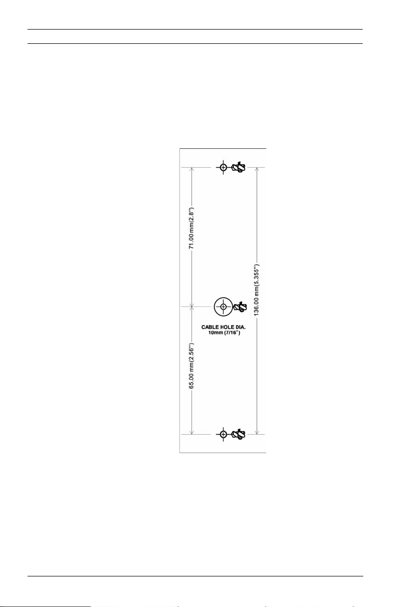
3.1 Mounting the ARD-AYCE65B 8
4 Wiring Instructions 9
5 Reader Functionality 11
5.1 Transmit Mode 11
5.2 Programming the ARD-AYCE65B Series 11
5.3 Selecting Keypad Transmission Format 13
5.3.1 Option No. 1: Single Key, 6-Bit Wiegand 15
5.3.2 Option No. 2: Single Key, 6-Bit Wiegand Nibble and Parities 15
5.3.3 Option No. 3: Single Key, 8-Bit Wiegand Nibbles Complemented
16
5.3.4 Option No. 4: 4 Keys Binary + Facility Code, 26-Bit Wiegand 16
5.3.5 Option No. 5: 1 to 5 Keys + Facility Code, 26-Bit Wiegand 17
5.3.6 Option No. 6: 6 Keys BCD and parity bits, 26-Bit Wiegand 18
5.3.7 Option No. 7: Single Key, 3x4 Matrix Keypad (ARD-MDP64) 19
5.3.8 Option No. 8: 1 to 8 Keys BCD, Clock & Data 19
5.4 Selecting Proximity Card Transmission Format 20
5.5 "Wiegand Card + PIN" Transmission Format 21
5.6 Changing the Programming Code 22
5.7 Changing the Facility Code 23
5.8 Setting the Backlight 23
5.9 Return to Factory Default Settings 24
5.10 Replacing a Lost Programming Code 24

ARD-AYCE65B General Information | en 5
Bosch Sicherheitssysteme GmbH Installation manual | V 1.1 | 2009.08
1 General Information
1.1 Introduction
The ARD-AYCE65B family is an Ultra-slim, vandal-resistant,
Piezo Mullion Keypad, access control reader.
The unit is vandal resistant and water resistant, suitable for
indoor or outdoor mounting.
This manual contains the following information:
– Installation
– Wiring instructions
–OperationInstructions
1.2 Box Content
Before beginning verify that all of the following is in the box. If
anything is missing, please report the discrepancy to your
nearest Bosch office.
– One ARD-AYCE65B unit
– Installation kit
– Installation and operating instructions

6en | Technical Specifications ARD-AYCE65B
| V 1.1 | 2009.08 Installation manual Bosch Sicherheitssysteme GmbH
2 Technical Specifications
Specifications ARD-AYCE65B
Electrical Characteristics
Power supply type Linear type - recommended
Operating voltage range 5 - 16VDC
Input current standby 92mA@12VDC
max Input current 105mA@16VDC
LED control input Dry contact N.O.
Tamper output Open collector, active low, 30mA
max sink current
Cable distance to host
controller
Up to 500ft (150 meters) using an
18AWG cable
Max proximity card read
range*
40mm (1.575 inch)
Proximity card
modulation
ASK at 125 KHz
Proximity card
compatibility
EM cards
Card Transmit format
(Reader)
26-bit Wiegand, or Clock & Data
Keypad Transmit Format
(Reader)
Programmable PIN code formats
LED indicators Two tri-colored LEDs
Communication Data1/Clock, Data0/Data- TTL
output
Environmental Characteristics
Operating temp. range -30 to 65° C (-22 to 150° F)
Operating humidity 0 - 95% (non-condensing)
Outdoor usage Weather-resistant, meets IP-68,
epoxy potted, suitable for outdoor
use
Mechanical

ARD-AYCE65B Technical Specifications | en 7
Bosch Sicherheitssysteme GmbH Installation manual | V 1.1 | 2009.08
*Measured using Bosch proximity card (ACD-ATR14CS) or
equivalent. Range also depends on electrical environment and
proximity to metal.
2.1 Key Features
The key features for the ARD-AYCE65B series are:
– Ultra-Slim Flush-mount design on flat surface
– Built-in piezoelectric keypad for PIN code entry
– Built-In 125 KHz ASK EM Proximity card reader
– Programmable Patented Blue backlit keypad
– Optical back tamper sensor and open collector tamper
output.
– Internal buzzer provides audible interface feedback
– Two status / programming Interface LEDs (tri-colored)
– Fully potted construction for outdoor use
– Comes with mounting template for easier installation
– Comes with an installation kit that includes a security
screw and a security screw tool
Reader
– Programmable keypad transmission format
– Programmable Card Transmission Formats: Clock & Data
and 26-Bit Wiegand
–LEDcontrolinput
– Programmable facility code
Size
(Height x Width x Depth)
155 x 44 x 9mm
6.1x1.73x0.354 inch
Weight 143g(0.315lb)
Specifications ARD-AYCE65B

8en | Installation ARD-AYCE65B
| V 1.1 | 2009.08 Installation manual Bosch Sicherheitssysteme GmbH
3 Installation
Before starting, select the location to mount the ARD-AYCE65B.
This location should be at shoulder height.
For wall mounting, use the included mounting template as a
guide for drilling holes for mounting screws and wiring. For US
Gang Box mounting, no drilling is necessary.
Figure 3.1 Drilling & Mounting Template
Route the interface cable from the ARD-AYCE65B to the
controller. A linear type power supply is recommended.
Screw the ARD-AYCE65B to its mounting location or US gang
box.

ARD-AYCE65B Wiring Instructions | en 9
Bosch Sicherheitssysteme GmbH Installation manual | V 1.1 | 2009.08
4 Wiring Instructions
The unit is supplied with a 1.5 meter (60-inch) pigtail, having a
6-conductor cable. To connect the unit to the controller,
perform the following:
Prepare the unit's cable by cutting the cable jacket back 1¼
inches and strip the wire ½ inch. Prepare the controller cable
by cutting the cable jacket back 1¼ inches and strip the wire ½
inch.
Splice the unit's pigtail wires to the corresponding controller
wires and cover each connection.
Refer to the wire color table below, and to the wiring diagram
provided on the following page.
If the tamper output is used, connect the purple wire to the
correct input on the controller.
Trim and cover all unused conductors.
Reader Color Functionality
5~16 VDC Red +DC Input
Shield/ Ground Black Ground
Data 1 / Clock White Communication
Data 0 / Data Green Communication
LEDCTL Brown LED Control / Auxiliary Input
Tamper Purple Tamper

10 en | Wiring Instructions ARD-AYCE65B
| V 1.1 | 2009.08 Installation manual Bosch Sicherheitssysteme GmbH
Figure 4.1 Reader Application Wiring Diagram
NOTICE!
– The individual wires from the unit are color-coded
according the Wiegand standard.
– When using a separate Power Supply for the Reader, this
Power Supply and that of the Controller must have a
common ground.
– The Reader's cable shield wire should preferably be
attached to an earth ground, or a signal ground connection
at the panel, or power supply end of the cable. This
configuration is best for shielding the Reader cable from
external interference

ARD-AYCE65B Reader Functionality | en 11
Bosch Sicherheitssysteme GmbH Installation manual | V 1.1 | 2009.08
5 Reader Functionality
The following explains how to use the ARD-AYCE65B reader.
5.1 Transmit Mode
When the ARD-AYCE65B is in Transmit Mode, it is ready to
receive data from a presented Proximity Card or an entered PIN
code.
When the reader is in Transmit Mode, the Transmit LED is red
and the Program LED is off.
When a Proximity Card or PIN entry is being transmitted, the
Transmit LED will flash green.
PIN data can be sent via one of eight different Keypad
Transmission Formats. For more information, see Selecting
Keypad Transmission Format on page 13.
Proximity Cards presented to the reader are always sent in
either 26-Bit Wiegand, Clock & Data or, Wiegand Card + PIN
format. See Selecting Proximity Card Transmission Format on
page 20 for more information.
5.2 Programming the ARD-AYCE65B Series
Programming the ARD-AYCE65B series is done solely via the
unit's keypad driven Programming Menu System. To reach the
Programming Menu System the ARD-AYCE65B must first be
placed into Programming Mode. During the ARD-AYCE65B's
manufacturing process certain codes and settings are pre-
programmed. These settings are called the "Default Factory
Settings".
The table below shows the names of all the ARD-AYCE65B
Menus.

12 en | Reader Functionality ARD-AYCE65B
| V 1.1 | 2009.08 Installation manual Bosch Sicherheitssysteme GmbH
Programming Menu
Default Factory Settings are marked by a "*" sign.
Menu Description Default
1 Selecting Keypad Transmission Format
Single Key, 6-Bit Wiegand (Rosslare Format)
Single Key, 6-Bit Wiegand with Nibble +
Parity Bits
Single Key, 8-Bit Wiegand, Nibbles
Complemented
4 Keys Binary + Facility Code, 26-Bit
Wiegand
1 to 5 Keys + Facility Code, 26-Bit Wiegand
6 Keys BCD and Parity Bits, 26-Bit Wiegand
Single Key, 3x4 Matrix Keypad
1 to 8 Keys BCD, Clock & Data
*
2 Selecting Card Transmission Format
26-Bit Wiegand
Clock & Data
Wiegand Card + PIN
*
3 Changing the Programming Code 1234
4 Changing the Facility Code 0
6 Backlight Options
Off
On (Default)
Off until key press when on for 10 seconds
Dimmed until key press when on for 10
seconds
*
0 Return to Factory Default Settings

ARD-AYCE65B Reader Functionality | en 13
Bosch Sicherheitssysteme GmbH Installation manual | V 1.1 | 2009.08
Entering Programming Mode
1. Press the # key 4 times.
– Transmit LED will turn off.
– Program LED will turn red.
2. Enter your 4 digit Programming Code. If the Programming
Code is valid, the door LED will turn green and the ARD-
AYCE65B will be in Programming Mode.
Exiting Programming Mode
1. To exit the Programming Mode at any time press #:
– You will hear a beep
– The Program LED will be off
– The Transmit LED will turn red
2. This indicates that the ARD-AYCE65B has returned to
Transmit Mode.
3. Wrong entries may reset the reader back to Transmit
Mode.
While in Programming Mode if no key is pressed for 30
seconds the ARD-AYCE65B will exit Programming Mode
and return to Transmit Mode.
5.3 Selecting Keypad Transmission Format
The ARD-AYCE65B has eight different keypad transmission
formats to select from. Follow the steps below to select the
appropriate keypad transmission format that you wish to use.
1. Enter Programming Mode.
2. Press "1" to enter.
"The Transmit LED will turn Red.
NOTICE!
– The factory 4-digit Programming Code is 1234.
– If a Programming Code is not entered within 30 seconds,
the ARD-AYCE65B will return to Transmit Mode.

14 en | Reader Functionality ARD-AYCE65B
| V 1.1 | 2009.08 Installation manual Bosch Sicherheitssysteme GmbH
3. Enter the appropriate option no. for the keypad
transmission format that you wish to select (see table
below).
If an incorrect option no. is entered the reader will return
to Transmit Mode and the keypad transmission format will
remain unchanged
4. Look on the next page for more information on keypad
transmission formats.
5. System returns to Transmit Mode.
– You will hear three beeps.
– The Program LED will turn off
– The Transmit LED will turn red
Keypad Transmission Format Option Number
See the table below to determine the Option Number for the
Keypad Transmission Format you wish to select.
NOTICE!
– Only one keypad transmission format can be active at any
one time.
– When using the keypad transmission format "1 to 8 keys
BCD, Clock & Data" (Option 8) an additional input is
required to specify the number of keys in the PIN code.
Keypad Transmission Format Option
Number
Single Key, 6-Bit Wiegand 1
Single Key, 6-Bit Wiegand with Nibble + Parity Bits 2
Single Key, 8-Bit Wiegand, Nibbles Complemented 3
4 Keys Binary + Facility Code, 26-Bit Wiegand 4
1 to 5 Keys + Facility Code, 26-Bit Wiegand 5
6 Keys BCD and Parity Bits, 26-Bit Wiegand 6
Single Key, 3x4 Matrix Keypad 7
1 to 8 Keys BCD, Clock & Data Single Key 8

ARD-AYCE65B Reader Functionality | en 15
Bosch Sicherheitssysteme GmbH Installation manual | V 1.1 | 2009.08
* Option No. 1 is the default factory setting.
More information on each of the different keypad transmission
formats is available below and on the following pages.
5.3.1 Option No. 1: Single Key, 6-Bit Wiegand
Each key press immediately sends 4 bits with 2 parity bits
added.
Even parity for the first 3 bits and odd parity for the last 3 bits.
* = Hexadecimal
5.3.2 Option No. 2: Single Key, 6-Bit Wiegand Nibble and
Parities
Each key press immediately sends 4 bits with 2 parity bits
added.
Even parity for the first 3 bits and odd parity for the last 3 bits.
* = Hexadecimal
0 = 110100 = "A" * 6 = 101100
1 = 000010 7 = 101111
2 = 000100 8 = 110001
3 = 000111 9 = 110010
4 = 101001 ? = 110111 ="B" *
5 = 101010 # = 011001 ="C" *
0 = 000001 6 = 101100
1 = 000010 7 = 101111
2 = 000100 8 = 110001
3 = 000111 9 = 110010
4 = 101001 ? = 110100 ="A" *
5 = 101010 # = 110111 ="B" *

16 en | Reader Functionality ARD-AYCE65B
| V 1.1 | 2009.08 Installation manual Bosch Sicherheitssysteme GmbH
5.3.3 Option No. 3: Single Key, 8-Bit Wiegand Nibbles
Complemented
Inverts the most significant bits in the message leaving the least
4 significant bits as Binary-Coded Decimal (BCD)
representation of the key. The host system receives an 8-bit
message.
* = Hexadecimal
5.3.4 Option No. 4: 4 Keys Binary + Facility Code, 26-Bit
Wiegand
Buffers 4 keys and outputs keypad data with a three digit
facility code like a standard 26-Bit card output.
The facility code is set in Programming Menu number four and
can be in the range 000 to 255. The factory default setting for
the facility code is 000. (See changing the Facility Code on page
22 for more information.)
The keypad PIN code is 4-digit long and can range between
0000 and 9999. On the fourth key press of the 4 digit PIN code,
the data is sent across the Wiegand Data lines as binary data in
the same format as a 26-Bit Card.
If the ? key or the # key are pressed during PIN code entry, the
keypad will clear the PIN code entry buffer, generate a beep
and is ready to receive a new 4 digit keypad PIN code.
If the entry of the 4 digits keypad PIN code is disrupted and no
number key is pressed within 5 seconds, the keypad will clear
the PIN code entry buffer, generate a beep and is ready to
receive a new 4 digits keypad PIN code.
(EP) FFFF FFFF AAAA AAAA AAAA AAAA (OP)
0 = 11110000 6 = 10010110
1 = 11100001 7 = 10000111
2 = 11010010 8 = 01111000
3 = 11000011 9 = 01101001
4 = 10110100 ? = 01011010 ="A" *
5 = 10100101 # = 01001011 ="B" *

ARD-AYCE65B Reader Functionality | en 17
Bosch Sicherheitssysteme GmbH Installation manual | V 1.1 | 2009.08
Where:
5.3.5 Option No. 5: 1 to 5 Keys + Facility Code, 26-Bit
Wiegand
Buffers up to 5 keys and outputs keypad data with a facility
code like a 26-Bit card output.
The facility code is set in Programming Menu number four and
can be in the range 000 to 255. The factory default setting for
the facility code is 000. (See changing the Facility Code on page
22 for more information.)
The keypad PIN code can be one to five digits long and can
range between 1 and 65,535. When entering a keypad PIN code
that is less than 5 digits long, the # key must be pressed to
signify the end of PIN code entry. For keypad PIN codes that are
5 digits long, on the fifth key press of the 5 digit PIN code, the
data is sent across the Wiegand Data lines as binary data in the
same format as a 26-Bit Card.
If the ? key is pressed during PIN code entry or a PIN code
greater than 65,535 is entered, the keypad will clear the PIN
code entry buffer, generate a beep and is ready to receive a
new 5 digit keypad PIN code.
If the entry of the 1 to 5 digit keypad PIN code is disrupted and
no number key or # key is pressed within 5 seconds, the keypad
will clear the PIN code entry buffer, generate a medium length
beep and is ready to receive a new 1 to 5 digit keypad PIN code.
(EP) FFFF FFFF AAAA AAAA AAAA AAAA (OP)
Where:
EP = Even parity for first 12 bits
OP = Odd parity for last 12 bits
F = 8-Bit Facility Code
A = 16-Bit code generated from keyboard

18 en | Reader Functionality ARD-AYCE65B
| V 1.1 | 2009.08 Installation manual Bosch Sicherheitssysteme GmbH
5.3.6 Option No. 6: 6 Keys BCD and parity bits, 26-Bit
Wiegand
Sends buffer of 6 keys, adds parity and sends a 26-Bit Binary-
Coded Decimal (BCD) message. Each key is a four bit
equivalent of the decimal number.
The keypad PIN code must be 6 key presses long. On the sixth
key press of the 6 digit PIN code, the data is sent across the
Wiegand Data lines as a BCD message.
If the entry of the 6 digit keypad PIN code is disrupted and no
number key is pressed within 5 seconds, the keypad will clear
the PIN code entry buffer, generate a medium length beep and
is ready to receive a new 6 digit keypad PIN code.
(EP) AAAA BBBB CCCC DDDD EEEE FFFF (OP)
Where:
EP = Even parity for first 12 bits
OP = Odd parity for last 12 bits
F = 8-Bit Facility Code
A = 16-Bit code generated from keyboard
EP = Even parity for first 12 bits
OP = Odd parity for last 12 bits
A = First key entered D = Fourth key entered
B = Second key entered E = Fifth key entered
C = Third key entered F = Sixth key entered

ARD-AYCE65B Reader Functionality | en 19
Bosch Sicherheitssysteme GmbH Installation manual | V 1.1 | 2009.08
5.3.7 Option No. 7: Single Key, 3x4 Matrix Keypad (ARD-
MDP64)
This unique mode is intended to let the host controller scan the
ARD-AYCE65B keypad while still keeping the proximity card
readers 26-Bit Wiegand or Clock & Data formats active.
An optional interface board must be used between the ARD-
AYCE65B and the host system. Each key press is immediately
sent on DATA0 as an ASCII character at a baud rate of 9600 bits
per second.
When a key is pressed DATA1 is pulled "low" until the key is
released at which point DATA1 will be set to "high". This allows
the controller to detect the duration of the key press.
The ARD-MDP64 interface unit outputs the data received to 7
outputs emulating a keyboard. The interface unit will not affect
any data that it receives from the proximity reader whether it is
26-Bit Wiegand or Clock & Data.
Key pressed = ASCII Value
5.3.8 Option No. 8: 1 to 8 Keys BCD, Clock & Data
Buffers up to 8 keys and outputs keypad data without a facility
code like standard Clock and Data card output.
The keypad PIN code can be one to eight digits long. The PIN
code length is selected while programming the reader for
Option 8. The reader will transmit the data when it receives the
last key press of the PIN code. The data is sent across the two
data output lines as binary data in Clock & Data format.
If the ? key or the # key are pressed during PIN code entry, the
keypad will clear the PIN code entry buffer, generate a beep
and is ready to receive a new keypad PIN code.
0 = '0' ( 0x30 hex ) 6 = '6' ( 0x36 hex )
1 = '1' ( 0x31 hex ) 7 = '7' ( 0x37 hex )
2 = '2' ( 0x32 hex ) 8 = '8' ( 0x38 hex )
3 = '3' ( 0x33 hex ) 9 = '9' ( 0x39 hex )
4 = '4' ( 0x34 hex ) ? = '*' ( 0x2A hex )
5 = '5' ( 0x35 hex ) # = '#' ( 0x23 hex )

20 en | Reader Functionality ARD-AYCE65B
| V 1.1 | 2009.08 Installation manual Bosch Sicherheitssysteme GmbH
If the entry of the digit keypad PIN code is disrupted and no
number key or # key is pressed within 5 seconds, the keypad
will clear the PIN code entry buffer, generate a medium length
beep and is ready to receive a new keypad PIN code.
5.4 Selecting Proximity Card Transmission
Format
The ARD-AYCE65B has three different proximity card formats to
select from. Follow the steps below to select the appropriate
Proximity Card reader transmission format that you wish to use.
1. Enter Programming Mode.
2. Press "2" to enter Menu 2.
The Transmit LED will turn red.
3. Enter the appropriate option number for the proxy card
transmission format that you wish to select (options
below).
If an incorrect option is entered the reader will return to
Transmit Mode and the keypad transmission format will
remain unchanged.
4. System returns to Transmit Mode
– You will hear three beeps.
– The Program LED will turn off
– The Transmit LED will turn red
Proximity Card Transmission Format Option Number:
Option 1: 26-Bit Wiegand
Option 2: Clock & Data
Option 3: Wiegand Card + PIN
NOTICE!
When using the keypad transmission format "1 to 8 keys BCD,
Clock & Data" (Option 8) an additional input is required to
specify the number of keys in the PIN code.
Table of contents