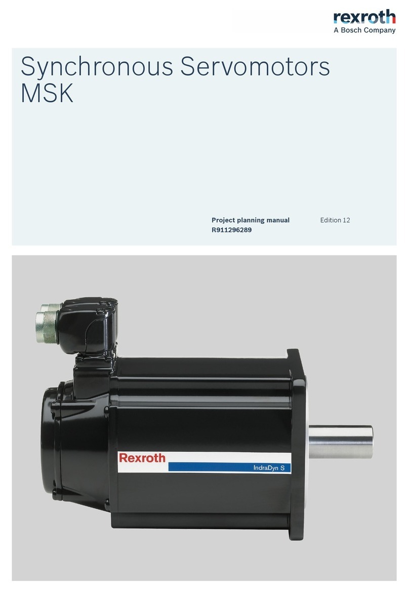
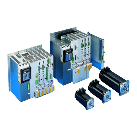
Bosch Rexroth IndraDrive Mi Technical manual

Project Planning Manual
Electric Drives
and Controls Pneumatics Service
Linear Motion and
Assembly Technologies
Hydraulics
Rexroth IndraDrive Mi
Drive Systems
R911320924
Edition 03

Rexroth IndraDrive Mi
Drive Systems
Project Planning Manual
DOK-INDRV*-KCU+KSM****-PR03-EN-P
RS-0ed5749a3227cd6a0a6846a00051a3ec-2-en-US-4
Edition Release Date Notes
DOK-INDRV*-KCU+KSM****-PR01-EN-P 2007/04 First edition
DOK-INDRV*-KCU+KSM****-PR02-EN-P 2008/02 Not published
DOK-INDRV*-KCU+KSM****-PR03-EN-P 2008/03 3rd edition; Changes:
See chapter "System
Presentation" → "About
this Documentation" →
"Changes"
© 2008 Bosch Rexroth AG
Copying this document, giving it to others and the use or communication of the
contents thereof without express authority, are forbidden. Offenders are liable
for the payment of damages. All rights are reserved in the event of the grant of
a patent or the registration of a utility model or design (DIN 34-1).
The specified data is for product description purposes only and may not be
deemed to be guaranteed unless expressly confirmed in the contract. All rights
are reserved with respect to the content of this documentation and the availa‐
bility of the product.
Bosch Rexroth AG
Bgm.-Dr.-Nebel-Str. 2 ■ D-97816 Lohr a. Main
Telephone +49 (0)93 52/ 40-0 ■ Fax +49 (0)93 52/ 40-48 85
http://www.boschrexroth.com/
Dept. BRC/EDY1 (RR/US/BB), BRC/EDM2 (JW)
This document has been printed on chlorine-free bleached paper.
Title
Type of Documentation
Document Typecode
Internal File Reference
Record of Revision
Bosch Rexroth AG |Electric Drives
and Controls
Rexroth IndraDrive Mi |Project Planning Manual
Copyright
Validity
Published by
Note

Table of Contents
Page
1 System Presentation...................................................................................................... 1
1.1 Introduction............................................................................................................................................. 1
1.1.1 Rexroth IndraDrive Mi.......................................................................................................................... 1
1.1.2 Features.............................................................................................................................................. 1
1.2 Drive System Rexroth IndraDrive Mi...................................................................................................... 2
1.2.1 Components........................................................................................................................................ 2
General Information.......................................................................................................................... 2
Lines................................................................................................................................................. 3
1.2.2 System Structure................................................................................................................................. 3
1.2.3 Overview of Functions......................................................................................................................... 8
Firmware Functions (Functional Packages)..................................................................................... 8
1.3 Type Code.............................................................................................................................................. 8
1.3.1 Introduction.......................................................................................................................................... 8
1.3.2 Distributed Servo Drive KSM............................................................................................................... 9
Type Code........................................................................................................................................ 9
Explanation of the Type Code........................................................................................................ 10
1.3.3 Electronic Control System KCU......................................................................................................... 12
Type Code...................................................................................................................................... 12
1.3.4 Firmware............................................................................................................................................ 12
1.4 About This Documentation................................................................................................................... 13
1.4.1 Document Structure........................................................................................................................... 13
1.4.2 Changes............................................................................................................................................ 13
1.4.3 Reference Documentations............................................................................................................... 14
Drive Systems, System Components............................................................................................. 14
Motors............................................................................................................................................. 14
Cables............................................................................................................................................ 14
Firmware......................................................................................................................................... 15
1.4.4 Your Feedback.................................................................................................................................. 15
2 Important Directions for Use ....................................................................................... 17
2.1 Appropriate Use ................................................................................................................................... 17
2.1.1 Introduction........................................................................................................................................ 17
2.1.2 Areas of Use and Application............................................................................................................ 17
2.2 Inappropriate Use................................................................................................................................. 18
3 Safety Instructions for Electric Drives and Controls..................................................... 19
3.1 Safety Instructions - General Information............................................................................................. 19
3.1.1 Using the Safety Instructions and Passing them on to Others.......................................................... 19
3.1.2 How to Employ the Safety Instructions.............................................................................................. 19
3.1.3 Explanation of Warning Symbols and Degrees of Hazard Seriousness............................................ 20
3.1.4 Hazards by Improper Use.................................................................................................................. 21
3.2 Instructions with Regard to Specific Dangers....................................................................................... 22
3.2.1 Protection Against Contact with Electrical Parts and Housings......................................................... 22
Project Planning Manual |Rexroth IndraDrive Mi Electric Drives
and Controls
|Bosch Rexroth AG I/VI
Table of Contents

Page
3.2.2 Protection Against Electric Shock by Protective Extra-Low Voltage................................................. 23
3.2.3 Protection Against Dangerous Movements....................................................................................... 23
3.2.4 Protection Against Magnetic and Electromagnetic Fields During Operation and Mounting.............. 26
3.2.5 Protection Against Contact with Hot Parts......................................................................................... 26
3.2.6 Protection During Handling and Mounting......................................................................................... 26
3.2.7 Battery Safety.................................................................................................................................... 27
3.2.8 Protection Against Pressurized Systems........................................................................................... 27
4 General Specifications of the Components.................................................................. 29
4.1 Certifications......................................................................................................................................... 29
4.2 Transport and Storage.......................................................................................................................... 31
4.2.1 Transport of the Components............................................................................................................ 31
4.2.2 Storage of the Components............................................................................................................... 31
4.3 Installation Conditions........................................................................................................................... 32
4.3.1 Ambient and Operating Conditions.................................................................................................... 32
4.3.2 Mounting Position.............................................................................................................................. 33
4.3.3 Compatibility With Foreign Matters.................................................................................................... 35
4.3.4 Prime Coat and Housing Varnish...................................................................................................... 35
4.4 Capacity Utilization............................................................................................................................... 36
4.5 Voltage Test and Insulation Resistance Test....................................................................................... 37
4.6 Control Voltage Specification (24V Supply).......................................................................................... 38
5 Technical Data of the Components.............................................................................. 41
5.1 Explanation of Terms and Definitions................................................................................................... 41
5.2 Distributed Servo Drive KSM................................................................................................................ 46
5.2.1 KSM Data Sheet................................................................................................................................ 46
5.2.2 KSM Characteristics.......................................................................................................................... 49
5.2.3 Dimensions and Technical Design.................................................................................................... 53
Dimensions..................................................................................................................................... 53
Technical Design............................................................................................................................ 57
5.2.4 Bearing Load and Shaft Load............................................................................................................ 57
5.3 Electronic Control System KCU............................................................................................................ 59
5.3.1 Brief Description and Usage.............................................................................................................. 59
5.3.2 Data Sheet KCU................................................................................................................................ 59
Data Sheet...................................................................................................................................... 59
5.3.3 Dimensional Drawing KCU................................................................................................................ 62
5.4 Hybrid Cables RKH............................................................................................................................... 62
5.4.1 Technical Data................................................................................................................................... 62
5.5 Selecting Hybrid Cable for Appropriate Connection............................................................................. 63
5.6 Interconnection Diagrams for Ready-Made Hybrid Cables.................................................................. 66
6 Connection Points........................................................................................................ 71
6.1 Connection Points of System................................................................................................................ 71
6.1.1 Equipment Grounding Conductor...................................................................................................... 71
6.1.2 Ground Connection........................................................................................................................... 71
II/VI Bosch Rexroth AG |Electric Drives
and Controls
Rexroth IndraDrive Mi |Project Planning Manual
Table of Contents

Page
6.2 Connection Points of KCU.................................................................................................................... 72
6.2.1 Positions of the Connection Points.................................................................................................... 72
6.2.2 X1, Module Bus................................................................................................................................. 73
6.2.3 X20 TX, X21 RX (SERCOS interface)............................................................................................... 74
General Information........................................................................................................................ 74
S6, SERCOS Transmission Power................................................................................................ 75
6.2.4 X50, E-Stop Input.............................................................................................................................. 75
6.2.5 X51, Master Communication SERCOS............................................................................................. 76
6.2.6 X52, Status Messages....................................................................................................................... 76
6.2.7 X53, Control Voltage Output.............................................................................................................. 77
6.2.8 X54, DC Bus, Equipment Grounding Conductor Output KSM........................................................... 77
6.2.9 DC Bus Connection L+, L-................................................................................................................. 78
6.2.10 Control Voltage Supply +24V, 0V...................................................................................................... 80
6.3 Connection Points of KSM.................................................................................................................... 81
6.3.1 Positions of the Connection Points.................................................................................................... 81
6.3.2 X2 Serial Interface, Service Input "Release Brake"........................................................................... 82
6.3.3 X3.1, X3.2 Connection Point Hybrid Cable........................................................................................ 84
6.3.4 X7 Connection Point MultiMediaCard ............................................................................................... 85
6.3.5 X37, X38 Digital Inputs/Output.......................................................................................................... 86
6.3.6 Second Connection Point of Equipment Grounding Conductor........................................................ 89
7 Notes on Project Planning........................................................................................... 91
7.1 Notes on Mechanical Project Planning................................................................................................. 91
7.1.1 Mounting Clearance.......................................................................................................................... 91
7.1.2 Output Shaft...................................................................................................................................... 91
Plain Shaft...................................................................................................................................... 91
Output Shaft With Key.................................................................................................................... 91
Output Shaft With Shaft Sealing Ring............................................................................................ 92
7.1.3 Bearings and Shaft Load................................................................................................................... 92
General Information........................................................................................................................ 92
Radial Load, Axial Load.................................................................................................................. 93
Bearing Service Life....................................................................................................................... 94
7.1.4 Holding Brakes.................................................................................................................................. 95
Brake Control and Supply............................................................................................................... 95
Safety Requirements...................................................................................................................... 95
Dimensioning Holding Brakes........................................................................................................ 97
7.1.5 Mechanical Attachment of Driving Elements..................................................................................... 97
General Information........................................................................................................................ 97
Redundant Bearings....................................................................................................................... 97
Gear Attachment............................................................................................................................ 98
Coupling Attachment...................................................................................................................... 98
Bevel Gear Pinions or Skew Bevel Driving Pinions........................................................................ 99
7.2 Notes on Electrical Project Planning..................................................................................................... 99
7.2.1 Power Supply.................................................................................................................................... 99
Supply Units................................................................................................................................... 99
7.2.2 Electronic Control System KCU....................................................................................................... 100
Project Planning Manual |Rexroth IndraDrive Mi Electric Drives
and Controls
|Bosch Rexroth AG III/VI
Table of Contents
Page
7.2.3 Available Power............................................................................................................................... 101
7.2.4 Number of KSM01 .......................................................................................................................... 104
7.2.5 Length of Hybrid Cable ................................................................................................................... 106
7.2.6 Distributed Servo Drive KSM........................................................................................................... 107
Address Selector Switch .............................................................................................................. 107
Motor Blower................................................................................................................................ 108
Motor Current Limitation............................................................................................................... 108
Motor Temperature....................................................................................................................... 109
Switching Frequency.................................................................................................................... 110
8 Identification............................................................................................................... 111
8.1 Scope of Supply.................................................................................................................................. 111
8.1.1 KSM................................................................................................................................................. 111
8.1.2 KCU................................................................................................................................................. 111
8.2 Identifying and Checking the Delivered Components......................................................................... 111
8.2.1 Type Plate KSM............................................................................................................................... 111
Arrangement................................................................................................................................. 111
Design.......................................................................................................................................... 112
8.2.2 Type Plate KCU............................................................................................................................... 113
Arrangement................................................................................................................................. 113
Design.......................................................................................................................................... 113
9 Mounting and Installation........................................................................................... 115
9.1 Introduction......................................................................................................................................... 115
9.1.1 Important Notes............................................................................................................................... 115
Safety........................................................................................................................................... 115
Qualified Technical Staff............................................................................................................... 115
9.1.2 System Overview............................................................................................................................. 115
Available Connections.................................................................................................................. 115
9.1.3 Connection Diagram KCU............................................................................................................... 117
9.2 Handling of the Devices...................................................................................................................... 118
9.3 Mounting............................................................................................................................................. 119
9.3.1 Practical Tips................................................................................................................................... 119
9.3.2 Required Steps to Follow................................................................................................................ 119
Preparations................................................................................................................................. 119
Mounting....................................................................................................................................... 119
9.3.3 Mechanical Interfaces...................................................................................................................... 119
Mounting the Flange..................................................................................................................... 119
9.3.4 Mounting KCU01 (Mounting Depth)................................................................................................ 120
9.4 Electrical Connection.......................................................................................................................... 120
9.4.1 General Information......................................................................................................................... 120
9.4.2 Notes............................................................................................................................................... 121
9.4.3 Electrical Interfaces......................................................................................................................... 121
Overall Connection Diagram........................................................................................................ 121
Parallel Strings of Drives.............................................................................................................. 126
IV/VI Bosch Rexroth AG |Electric Drives
and Controls
Rexroth IndraDrive Mi |Project Planning Manual
Table of Contents

Page
10 Accessories................................................................................................................ 127
10.1 Overview............................................................................................................................................. 127
10.2 HAS01, Basic Accessory.................................................................................................................... 127
10.3 HAS02, Strain Relief and Shield Connection...................................................................................... 128
10.4 HAS03, Control Cabinet Adapter........................................................................................................ 128
10.5 RKB0006, Interface Cable.................................................................................................................. 129
10.5.1 Usage.............................................................................................................................................. 129
11 Commissioning, Operation, Diagnoses, Service and Maintenance........................... 131
11.1 Notes on Commissioning.................................................................................................................... 131
11.1.1 General Information......................................................................................................................... 131
11.1.2 Preparation...................................................................................................................................... 131
11.1.3 How to Proceed............................................................................................................................... 131
11.2 Notes on Operation............................................................................................................................. 131
11.3 Diagnostic Functions.......................................................................................................................... 132
11.3.1 Distributed Servo Drive KSM........................................................................................................... 132
11.3.2 Electronic Control System KCU....................................................................................................... 133
11.3.3 Diagnostic Messages via Parameters............................................................................................. 134
11.3.4 Firmware Functions......................................................................................................................... 134
Easy Startup Mode....................................................................................................................... 134
Analog Outputs............................................................................................................................. 135
Oscilloscope Function.................................................................................................................. 135
Patch Function.............................................................................................................................. 135
Monitoring Function...................................................................................................................... 135
11.4 Service Functions / Troubleshooting.................................................................................................. 135
11.4.1 General Information......................................................................................................................... 135
11.4.2 Replacement of Fuses F4 and F5................................................................................................... 135
11.4.3 Deactivating and Dismounting the Drive......................................................................................... 136
Deactivation.................................................................................................................................. 136
Dismounting.................................................................................................................................. 137
11.4.4 Replacement of KSM....................................................................................................................... 137
11.4.5 Service Function "Release Holding Brake" ..................................................................................... 137
11.4.6 Saving Parameters.......................................................................................................................... 138
11.4.7 Firmware Update............................................................................................................................. 138
11.4.8 MMC................................................................................................................................................ 138
11.5 Maintenance....................................................................................................................................... 139
11.5.1 Maintenance of the Motor Component............................................................................................ 139
General Information...................................................................................................................... 139
Cleaning ...................................................................................................................................... 139
Bearings....................................................................................................................................... 140
Connection Cables....................................................................................................................... 140
Holding Brake–Commissioning and Maintenance Instructions..................................................... 140
11.5.2 Maintenance of the Electronic System of the Drive......................................................................... 141
Project Planning Manual |Rexroth IndraDrive Mi Electric Drives
and Controls
|Bosch Rexroth AG V/VI
Table of Contents

Page
12 Environmental Protection and Disposal..................................................................... 143
12.1 Environmental Protection.................................................................................................................... 143
12.1.1 Production Processes...................................................................................................................... 143
12.1.2 Prohibited Substances..................................................................................................................... 143
12.1.3 No Release of Hazardous Substances............................................................................................ 143
12.1.4 Principal Components..................................................................................................................... 143
12.2 Disposal.............................................................................................................................................. 143
12.2.1 Return of Products........................................................................................................................... 143
12.2.2 Packaging Materials........................................................................................................................ 143
12.2.3 Recycling......................................................................................................................................... 144
13 Service and Support.................................................................................................. 145
13.1 Helpdesk............................................................................................................................................. 145
13.2 Service Hotline.................................................................................................................................... 145
13.3 Addresses........................................................................................................................................... 145
13.4 Helpful Information.............................................................................................................................. 145
14 Appendix.................................................................................................................... 147
14.1 Discharging of Capacitors................................................................................................................... 147
14.1.1 Discharging of DC Bus Capacitors.................................................................................................. 147
14.1.2 Discharging Device.......................................................................................................................... 147
Operating Principle....................................................................................................................... 147
Dimensioning................................................................................................................................ 148
How to Proceed for Discharging................................................................................................... 148
Index.......................................................................................................................... 149
VI/VI Bosch Rexroth AG |Electric Drives
and Controls
Rexroth IndraDrive Mi |Project Planning Manual
Table of Contents

1 System Presentation
1.1 Introduction
1.1.1 Rexroth IndraDrive Mi
Rexroth IndraDrive Mi is an innovative system solution within the Rexroth In‐
draDrive platform, consisting of synchronous servo motors (on the basis of
Rexroth IndraDyn S) with integrated inverters and control sections.
1.1.2 Features
Fig.1-1: Rexroth IndraDrive Mi – Features
Project Planning Manual |Rexroth IndraDrive Mi Electric Drives
and Controls
|Bosch Rexroth AG 1/152
System Presentation

In the following points, the system solution Rexroth IndraDrive Mi differs from
a standard solution with Rexroth IndraDrive and Rexroth IndraDyn:
● Limited performance levels and exclusively available on the basis of
Rexroth IndraDyn S, i.e. no linear and kit motors
● SERCOS interface as master communication
1.2 Drive System Rexroth IndraDrive Mi
1.2.1 Components
General Information
The drive system Rexroth IndraDrive Mi consists of the following components:
1 Distributed servo drive KSM ; 1a: basic motor ; 1b: electronic system of
drive (power section and control section)
2 Terminal connector RHS (to close the SERCOS ring)
3 Hybrid cable RKH (for power and communication)
4 Electronic control system KCU (power supply and signal conversion)
Fig.1-2: Components
The distributed servo drive KSM consists of 2 parts:
● Servo motor (on the basis of Rexroth IndraDyn S)
● Electronic system of drive, consisting of control section and power section
The hybrid cable RKH replaces the following individual cables:
● Motor power cable
● Encoder cable
● Control voltage and signal exchange cable
● SERCOS cable
The hybrid cable is supplied in ready-made form with connectors.
The electronic control system KCU
2/152 Bosch Rexroth AG |Electric Drives
and Controls
Rexroth IndraDrive Mi |Project Planning Manual
System Presentation
Differences to Rexroth IndraDrive
and Rexroth IndraDyn
Distributed Servo Drive KSM
Hybrid Cable RKH
Electronic Control System KCU

● supplies power to the distributed servo drives KSM (from the DC bus con‐
nection to an HMV supply unit or HCS converter)
● with integrated fuses protects the hybrid cable RKH against electric over‐
load
● allows communication between the higher-level control unit and the dis‐
tributed servo drives KSM
Lines
See section "Type Code"
● Distributed servo drive KSM
● Electronic control system KCU
1.2.2 System Structure
The supply unit which is used significantly defines the system structure.
Possible supply units:
● Rexroth IndraDrive supply unit HMV01.1E/R or HMV02.1R
●Rexroth IndraDrive converter HCS02.1 or HCS03.1 (makes sense if an‐
other axis is required)
Project Planning Manual |Rexroth IndraDrive Mi Electric Drives
and Controls
|Bosch Rexroth AG 3/152
System Presentation

Drive system Rexroth IndraDrive Mi with HMV01 supply unit:
24V 24V supply
DST Transformer (optional)
F Fuses
HMD, HMS Inverter (optional)
HMV01 Supply unit
HNF Mains filter
HNL Mains choke
K1 Mains contactor (only for supply units without integrated mains contac‐
tor, e.g. HMV01.1R-W0120)
KCU Electronic control system
KSM Distributed servo drive
MSK Servo motor (optional)
RHS Terminal connector
RKG Encoder cable (optional)
RKH Hybrid cable
RKL Motor cable (optional)
X14 Mains synchronization (only with regenerative HMVs)
X3.2 Connection of hybrid cable RKH at first KSM
Fig.1-3: Drive system Rexroth IndraDrive Mi with HMV01
4/152 Bosch Rexroth AG |Electric Drives
and Controls
Rexroth IndraDrive Mi |Project Planning Manual
System Presentation

Drive system Rexroth IndraDrive Mi with HMV02 supply unit:
24V 24V supply
DST Transformer (optional)
F Fuses
HMS02 Inverter (optional)
HMV02 Supply unit
HNS02 Mains filter with switch-disconnector
HNL02 Mains choke
KCU Electronic control system
KSM Distributed servo drive
MSK Servo motor (optional)
RHS Terminal connector
RKG Encoder cable (optional)
RKH Hybrid cable
RKL Motor cable (optional)
X14 Mains synchronization (only with regenerative HMVs)
X3.2 Connection of hybrid cable RKH at first KSM
Fig.1-4: Drive system Rexroth IndraDrive Mi with HMV02
Project Planning Manual |Rexroth IndraDrive Mi Electric Drives
and Controls
|Bosch Rexroth AG 5/152
System Presentation

Drive system Rexroth IndraDrive Mi with HCS02 supply unit:
DST Transformer (optional)
FFuses
HCS02 Converter
HNF Mains filter
HNL Mains choke (optional)
K1 Mains contactor
KCU Electronic control system
KSM Distributed servo drive
MSK Servo motor
24V 24V supply
RHS Terminal connector
RKG Encoder cable
RKH Hybrid cable
RKL Motor cable
X3.2 Connection of hybrid cable at first KSM
Fig.1-5: Drive system Rexroth IndraDrive Mi with HCS02
6/152 Bosch Rexroth AG |Electric Drives
and Controls
Rexroth IndraDrive Mi |Project Planning Manual
System Presentation

Drive system Rexroth IndraDrive Mi with HCS03 supply unit:
DST Transformer (optional)
F Fuses
HCS03 Converter
HNF Mains filter
HNL Mains choke (optional)
K1 Mains contactor
KCU Electronic control system
KSM Distributed servo drive
MSK Servo motor
RHS Terminal connector
RKH Hybrid cable
RKG Encoder cable
RKL Motor cable
24V 24V supply
X3.2 Connection of hybrid cable at first KSM
Fig.1-6: Drive system Rexroth IndraDrive Mi with HCS03
Project Planning Manual |Rexroth IndraDrive Mi Electric Drives
and Controls
|Bosch Rexroth AG 7/152
System Presentation

1.2.3 Overview of Functions
Firmware Functions (Functional Packages)
For the available firmware functions, see chapter "Functional Pack‐
ages" of the Functional Description for firmware MPB04VRS or
higher.
Hardware-related functional restrictions as compared to drive controllers with
CSB and CSH control sections:
●No safety technology
● No analog inputs or outputs
● No digital and analog I/O extensions
1.3 Type Code
1.3.1 Introduction
The type code is the basis of each purchase order of a Rexroth product.
It unequivocally describes all variants which can be supplied.
● Distributed servo drive KSM
● Electronic control system KCU
● Firmware ≥ MPB04-V20
For product selection and purchase order, take the following aspects into ac‐
count:
● Observe detailed information and instructions in the chapters "Technical
Data of the Components" and "Notes on Project Planning"
● Before placing a purchase order, have our sales representative check
whether individual options are available
The following figure illustrates the basic structure of the type code.
Our sales representative will help you with the current status of
available versions.
8/152 Bosch Rexroth AG |Electric Drives
and Controls
Rexroth IndraDrive Mi |Project Planning Manual
System Presentation
Notes on Product Selection

1.3.2 Distributed Servo Drive KSM
Type Code
Fig.1-7: Type code KSM
Project Planning Manual |Rexroth IndraDrive Mi Electric Drives
and Controls
|Bosch Rexroth AG 9/152
System Presentation

Explanation of the Type Code
The type code has the following basic structure:
●Product
KSM Designation of the line
●Size
The size defines important mechanical dimensions. In addition, the rotor inertia
is distinguished in column 11.
Abbrev. column <12> : 1 Rotor inertia reduced
6 Rotor inertia normal
●Length
Within one line, increasing length is graded by code letters in alphabetic order.
●Winding
The two-digit sequence of numerals, multiplied by 100, makes the rated speed
applying to the corresponding winding variant.
●Cooling mode
N: Natural convection
●Motor encoder
Rexroth IndraDrive Mi motors have been equipped with an integrated encoder
system. To control the motor speed or position the motor, the drive controller
needs the current motor position.
Option Encoder type
S1 Optical encoder single-turn, position detection absolute over 1 motor rev‐
olution with a resolution of 128 x 213 pieces of information per revolution
M1 Optical encoder multi-turn, position detection absolute over 4096 motor
revolutions with a resolution of 128 x 213 pieces of information per revolution
Fig.1-8: Motor encoder
●Connection system
Connection for hybrid cable RKH
●Shaft
To connect the machine elements to be driven to the motor shafts, there are
the following options.
Option Design Detail
GPlain shaft With centering hole on the end face with
thread "DS" according to DIN 332, part 2,
edition 05.83
PShaft with keyway 1)
1) Keyway according to DIN 6885, sheet 1, edition 08.68 (for details see dimensional
drawing!)
Fig.1-9: KSM output shafts
Distributed servo drives KSM are balanced with the complete key.
The corresponding key is not part of the scope of supply.
●Holding brake
10/152 Bosch Rexroth AG |Electric Drives
and Controls
Rexroth IndraDrive Mi |Project Planning Manual
System Presentation
Abbrev. column 1 2 3 4 5 6 7 8
Abbrev. column 10 11 12
Abbrev. column 13
Abbrev. column 15 16
Abbrev. column 17
Abbrev. column 19 20
Abbrev. column 22
Abbrev. column 23

Distributed servo drives KSM can be optionally supplied with electrically re‐
leased holding brakes.
Option Holding brakes
0Without holding brake
2 With holding brake For holding torques, see individual data
sheets.
Fig.1-10: KSM holding brakes
The holding brake is not suited for personal protection or as service
brake! Observe the installation and safety instructions for the motor
holding brakes!
●Master communication
SE: SERCOS (RS422)
●Safety option (X41)
NN: None
●Connecting voltage
D7: DC 750 V
●Other design
NN: None
●Firmware
FW: Firmware must be ordered as separate subposition
●Standard reference
The item "Standard reference" refers to standards cited in the type code (e.g.
DIN, EN, ISO ...) or reference INN... factory standards. The type code lists the
edition valid at the point of time the type code is issued.
Project Planning Manual |Rexroth IndraDrive Mi Electric Drives
and Controls
|Bosch Rexroth AG 11/152
System Presentation
Abbrev. column 24
Abbrev. column 26 27
Abbrev. column 29 30
Abbrev. column 32 33
Abbrev. column 35 36
Abbrev. column 38 39

1.3.3 Electronic Control System KCU
Type Code
Fig.1-11: Type code KCU
1.3.4 Firmware
Operating a Rexroth IndraDrive Mi drive system requires the standard firmware
MPB04-V20 or higher.
Type code: See Functional Description of firmware
12/152 Bosch Rexroth AG |Electric Drives
and Controls
Rexroth IndraDrive Mi |Project Planning Manual
System Presentation
Other manuals for Rexroth IndraDrive Mi
3
Table of contents
Other Bosch Servo Drive manuals

Bosch
Bosch Rexroth IndraDrive Mi User manual

Bosch
Bosch Rexroth EC302 User manual

Bosch
Bosch Rexroth Servodyn-D Series Instruction Manual

Bosch
Bosch MSK030B-0900-NN Technical manual

Bosch
Bosch Rexroth IndraDrive Mi Technical manual

Bosch
Bosch Rexroth MS2S User manual

Bosch
Bosch Rexroth MSK Technical manual

Bosch
Bosch Rexroth IndraDrive Mi Technical manual

Bosch
Bosch rexroth Servodyn-T User manual