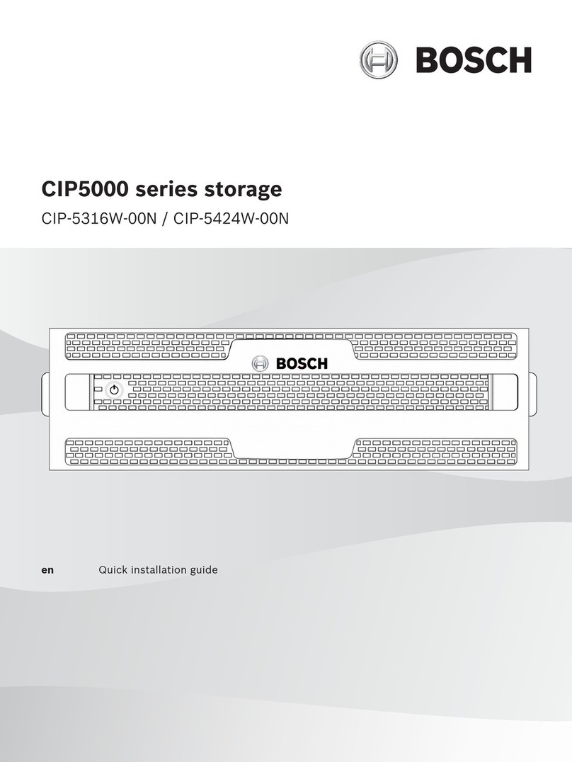
Bosch CIP5000 Series User manual

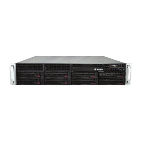
CIP5000 series storage
CIP‑5316W‑00N/CIP‑5424W‑00N/CIP‑5316‑JBOD
en User manual


CIP5000 series storage Table of contents | en 3
Bosch Security Systems B.V. User manual 2019-10 | V01 | F.01U.380.030
Table of contents
1Safety 6
1.1 RoHS compliance 6
2Introduction 7
3Specifications 8
4Hardware 10
4.1 Front panel hardware 10
4.1.1 Front panel of CIP-5316W/5424W-00N 10
4.1.2 Front panel of CIP-5316-JBOD 11
4.1.3 Front panel LEDs 11
4.2 Rear panel hardware 13
4.2.1 Rear panel of CIP-5316W/5424W-00N 13
4.2.2 Rear panel LEDs of CIP-5316W/5424W-00N 14
4.2.3 Rear panel connections of CIP-5316W/5424W-00N 14
4.2.4 Rear panel LEDs of CIP-5316-JBOD 15
4.2.5 Rear panel connections of CIP-5316-JBOD 16
4.3 Secure cover 16
5Hardware configuration 18
5.1 Unpacking 18
5.2 Install enclosure on the rack 18
5.2.1 Install the enclosure 20
5.2.2 Install or remove the secure cover 22
5.3 Install disk drives 22
5.3.1 Drive slot numbering 23
5.3.2 Remove the drive carrier 23
5.3.3 Install 3.5" disk drive in the carrier 24
5.4 Management path connection 25
5.4.1 SAS JBOD expansion 25
5.5 Connect the power supply 26
5.6 Power on 27
6Management GUI 28
6.1 Login 28
6.1.1 Local login 28
6.1.2 Network login 28
6.1.3 Login screen 29
6.2 Use Management GUI 30
6.2.1 Use the header 30
6.2.2 Use the tree view 30
6.2.3 Use the management view 31
6.3 Choose a display language 31
6.4 View the event frame 31
6.5 Logout 32
7Subsystems management 33
8Backgroud activities 34
8.1 Manage background activities settings 34
8.1.1 Rebuild the settings 35
8.1.2 Background synchronization rate 35
8.1.3 Logical drive initialization 35
8.1.4 Redundancy check 36

4en | Table of contents CIP5000 series storage
2019-10 | V01 | F.01U.380.030 User manual Bosch Security Systems B.V.
8.1.5 PDM 36
8.1.6 Transition 37
8.2 Media patrol 37
9Manage activity schedules 38
9.1 Add or delete activity schedules 38
9.2 View or modify an existing activity schedule 38
10 Event log 39
11 Administrative tools 40
11.1 Restore factory default settings 40
11.2 Clear statistics 40
12 User management 41
12.1 View user information 41
12.2 User settings 41
12.2.1 Change your own user settings 41
12.2.2 Change your own password 41
12.3 Create a user 41
12.3.1 User rights 42
12.3.2 Delete a user 42
12.4 View network settings 42
12.5 Software management 43
12.5.1 Import a configuration script 43
12.5.2 Export a configuration script 43
12.5.3 Save a service report 43
12.6 Email service 44
12.6.1 Stop Email service 44
12.6.2 Restart Email service 45
12.6.3 Email settings 45
12.6.4 Send test Email message 45
13 Performance monitoring 46
14 Controllers 48
14.1 View controller information 48
14.2 View controller statistics 48
14.3 Controller settings 49
15 Enclosures 50
15.1 Enclosure information 50
15.2 Temperature sensor settings 50
15.3 Buzzer settings 51
16 Physical drives 52
17 Disk arrays and logical drives 54
17.1 Logical drive management 55
18 Spare drives 56
18.1 Run spare check 56
19 Logical drive summary 57
20 Maintenance 58
20.1 Remove the failed PSU 58
20.2 Install a new PSU 58
21 Troubleshooting 59
21.1 How to diagnose hard drive failures 59
21.1.1 Check HDD status LEDs 59

CIP5000 series storage Table of contents | en 5
Bosch Security Systems B.V. User manual 2019-10 | V01 | F.01U.380.030
21.1.2 Check HDD status in Management GUI 59
21.1.3 Prevent HDD problems 60
21.2 Rebuild a disk array 61
21.2.1 How to rebuild a disk array 61
21.3 How to save a service report 63
21.4 How to diagnose the alarm buzzer 64
21.4.1 How to disable the alarm buzzer 64

6en | Safety CIP5000 series storage
2019-10 | V01 | F.01U.380.030 User manual Bosch Security Systems B.V.
1 Safety
!
Warning!
This is a Class A product. In a domestic environment this product may cause radio
interference in which case the user may be required to take adequate measures.
Danger!
Consequences The electronic components within the enclosure are sensitive to damage from
Electro-Static Discharge (ESD). Observe appropriate precautions at all times when handling
the device or its subassemblies.
!
Warning!
Turn off the power and disconnect the power cord before servicing this device.
1.1 RoHS compliance
CIP5000 series storage
Hazardous substance table according to SJ/T 11364-2014
Pb
(Pb)
Hg
(Hg)
Cd
(Cd)
Cr 6+
(Cr 6+)
PBB
(PBB)
PBDE
(PBDE)
PCBA X O O O O O
Housing & enclosures X O O O O O
Cables O O O O O O
Power supply units X O O O O O
Batteries X O O O O O
This table was created according to the provisions of SJ/T 11364
O: The content of such hazardous substance in all homogeneous materials of such
component is below the limit defined in GB/T 26572
X: The content of such hazardous substance in a certain homogeneous material is above the
limit defined in GB/T 26572

CIP5000 series storage Introduction | en 7
Bosch Security Systems B.V. User manual 2019-10 | V01 | F.01U.380.030
2 Introduction
CIP5000 series storage devices are subjected to a special design, and suitable for medium and
large IP video monitoring projects. CIP5000 series storage are most suited for continuous
monitoring in banks, shopping malls, casinos, factories, warehouses, and similar sized
commercial buildings, residential areas, governmental or private enterprise.
CIP5000 series storage can simplify the installation and setup process by configuring Windows
Storage Server 2016 Standard (64-bit) Operating System, a video management software suite
as well as hot-swappable hard drives.
CIP5000 series storage devices are integrated servers with built-in RAID storage functions,
thus eliminating the need for additional servers, RAID controller cards and separately
connected storage cases.
CIP5000 series storage uses thoroughly tested and proven RAID engines and can maximize
reliability, all of the drive bays are hot-swappable, and these products are equipped with
redundant power supply, which can ensure data security and uninterrupted run.
PCIe slots incorporated in CIP5000 storage devices can improve flexibility. PCIe slots are
applicable to other useful functions on video graphics cards, video encoder/decoder cards,
RAID cards or PCIe platforms.
Storage capacity can be expanded by means of the CIP-5316-JBOD 3U 16-bay extension
cabinet.

8en | Specifications CIP5000 series storage
2019-10 | V01 | F.01U.380.030 User manual Bosch Security Systems B.V.
3 Specifications
Model CIP-5316W-00N CIP-5424W-00N
General
Form factor 3U, 19” rack mount 4U, 19” rack mount
Function Storage appliance for video surveillance
Drives 16 hot-swappable drives
3.5” HDD (12Gbs SAS / 6Gbs
SATA)
24 hot-swappable drives
3.5” HDD (12Gbs SAS / 6Gbs
SATA)
Controller Single
Network Two Gigabit Ethernet RJ-45 ports (1000Base-T)
System processor Intel® Core™ i3-7101E
System memory Default 8GB (Maximum 64 GB) @ DDR4 Non-ECC
Internal built-in storage 128GB M.2
Number of HDD
supported
Up to 96 HDD via 5 JBODs Up to 104 HDD via 5 JBODs
USB ports Front: two USB 2.0
Rear: four USB 3.0
Expansion slot 1x8-lane gen3
1x1-lane gen3
1x4-lane gen3
I/O port PS/2 x 1
D-Sub Port x 1
DVI Port x 1
HDMI Port x 1
Audio 5 + 1 jack
RAID levels supported 0, 1, 1E, 3, 5, 6, 10 (0+1), 30, 50, 60
Hot spares Multiple global or dedicated hot-spare drives with revertible option
Maximum LUNs per
system/array
256/32
Software
Supported OS (64-bit) Windows Storage Server 2016 Standard
Management Graphical UI/SNMP via Ethernet, CLI via Ethernet, OPAS Service
via USB, SDK or API for Integration
Event notification Email, SNMP, Buzzer, LEDs
System
AC input 100 ~ 240 VAC, 60 ~ 50Hz
Current (maximum) 8-4A ( 550W, 8A/100V, 4A/240V)

CIP5000 series storage Specifications | en 9
Bosch Security Systems B.V. User manual 2019-10 | V01 | F.01U.380.030
Model CIP-5316W-00N CIP-5424W-00N
Power supply 550W (1+1@550W) in default.
Fan Non-swappable
Temperature 5° ~ 40°C (-40° ~ 60°C non-operational)
Relative humidity Operational: 10% to 80% (Non-Condensing)
Non-Operational: 10% to 95% (Non-Condensing)
Dimensions (H x W x D) 131 x 503 x 447 mm
(5.1 x 19.8 x 17.6 in)
173 x 503 x 447 mm
(6.8 x 19.8 x 17.6 in)
Safety/EMI CE, CCC
Warranty 3 years limited warranty
Model CIP-JBOD
General
Form factor 3U, 19” rack mount
Function JBOD storage expansion cabinet for CIP5000
Drives SAS (3 Gb / s or 6 Gb / s) /
SATA (3 Gb / s or 6 Gb / s)
System
AC input 100 ~ 240 VAC, 60 ~ 50Hz
Current (maximum) 8A
Power supply 550W (1+1@550W) in default.
Power consumption 177.9 watts (w / SAS drives)
44.9 watts (without drives)
Fan Non-swappable
Temperature 5° ~ 40°C (-40° ~ 60°C non-operational)
Relative humidity Operational: 20% to 80% (Non-Condensing)
Non-Operational: ~ 95% (Non-Condensing)
Dimensions (H x W x D) 131 x 446.7 x 507 mm
(5.1 x 17.6 x 19.96 in)
Safety/EMI CE
Warranty 3 years limited warranty

10 en | Hardware CIP5000 series storage
2019-10 | V01 | F.01U.380.030 User manual Bosch Security Systems B.V.
4 Hardware
This sections gives an overview of the front panel and rear panel hardware features of
CIP-5316W-00N, CIP-5424W-00N storage devices, and CIP-5316-JBOD storage expansion.
In this document, these products are referred to as CIP5000 enclosures, CIP5000 units, or
CIP5000 systems. The contents of this document apply to all models in the CIP5000 series
storage.
4.1 Front panel hardware
Without the secure cover, the front panel of the enclosures allows access to drives carriers.
So the units are shipped with secure covers to protect the drive carriers from being
unintentionally removed.
Defective drives shall be replaced immediately in order to ensure data availability. If any drive
failed, a hot spare drive automatically replaces a failed drive, thus ensuring the fault-tolerant
integrity of the logical drive. The self-contained hardware-based RAID logical drives provide
maximum performance in a compact external enclosure.
4.1.1 Front panel of CIP-5316W/5424W-00N
The front panel hardware components on the CIP-5316W-00N and CIP-5424W-00N are
identical except the number of drives.
Each side of enclosure is equipped with a handle to secure the enclosure to the rack.
The system power button and two USB ports are located on the left handle, and most of the
front LED indicators are located on the right handle.
Drive carriers Power and Status LEDs
Figure4.1: CIP-5316W-00N front view

CIP5000 series storage Hardware | en 11
Bosch Security Systems B.V. User manual 2019-10 | V01 | F.01U.380.030
Drive carriers Power and Status LEDs
Figure4.2: CIP-5424W-00N front view
4.1.2 Front panel of CIP-5316-JBOD
The front panel hardware components on the CIP-5316-JBOD is nearly the same as
CIP-5316W-00N. However, there is no power button, USB ports and OPAS LED on the left
handle of CIP-5316-JBOD enclosure.
The hard disk status and hard disk activity indicators on the hard drive carriers have the same
functions as those on CIP-5316W-00N enclosure.
The LEDs of power, system status, global hard disk activity, and system heartbeat indicator on
the right handle have the same functions as those of CIP-5316W-00N.
4.1.3 Front panel LEDs
With the power supplies connected, the system can now be powered on.
To power on the subsystem, press the power button on the left handle, then observe OPAS
LED on the left handle and LEDs on the right handle.
USB ports
OPAS LED
Power button
Figure4.3: Front panel components on the left handle

12 en | Hardware CIP5000 series storage
2019-10 | V01 | F.01U.380.030 User manual Bosch Security Systems B.V.
Power
System status
Global RAID status
Global HDD activity
(Reserved)
System heartbeat
Figure4.4: Front panel LEDs on the right handle
LED Description
Power Blue - System is powered on.
System status Green - System is normal.
Red - System trouble. Such as LD offline, fan malfunction, voltage
out of range, system temperature alert.
Red flash - HDD high temperature alert
Off steady - System is not ready.
Global RAID status Green - Status is normal.
Red - RAID volume is offline.
Orange - Critical state of any logical drive, or system is rebuilding.
Global HDD activity Blue flash - One or more drives are being accessed.
Blue - No drives are being accessed.
System heartbeat Blue flash - Firmware and software are operating normally.
OPAS USB Green - OPAS device (USB disk) is detected.
Green flash - OPAS operation is in progress.
Red - OPAS operation has failed.
Drive Status (OK)
Activity
Figure4.5: Hard disk drive carrier LEDs
There are two LEDs on each drive carrier. They report activity of the drive, and current
condition of the drive.
LED Description
Disk status Green - HDD is configured and working properly.
Red - HDD requires manual replacement.
Orange - Status notification of background RAID activity on this
articular HDD, and no user action is required.
Disk activity Blue flash - During drive activity.

CIP5000 series storage Hardware | en 13
Bosch Security Systems B.V. User manual 2019-10 | V01 | F.01U.380.030
4.2 Rear panel hardware
The rear panel of the enclosure provides access to the hot-swappable power supplies, local
management connection (via USB keyboard and VGA or HDMI monitor port), iSCSI (Ethernet)
data ports, and some units also provide I/O connections for audio sensor and alarm systems.
The rear panel includes two system fans.
4.2.1 Rear panel of CIP-5316W/5424W-00N
The rear panel of CIP-5424W-00N is almost the same as the rear panel of the CIP-5316W-00N
except for its higher profile. The form factor of the CIP-5424W-00N is 4U and the form factor
of the CIP-5316W-00N is 3U.
The rear panel is where you connect power cables, I/O connections, IPMI port, audio out/in,
video (VGA), USB serial ports, COM1 (serial port) and SAS port Backend Controller card. Both
enclosures include PCIe slots for added system versatility.
Figure4.6: CIP-5316W-00N rear view
Figure4.7: CIP-5424W-00N rear view
The rear panel components of CIP-5316W-00N and CIP-5424W-00N are the same, and each
model has two power supply units (PSU).

14 en | Hardware CIP5000 series storage
2019-10 | V01 | F.01U.380.030 User manual Bosch Security Systems B.V.
12
10
11
3
4 6 7 95 8
1 PSU fan vents
2 Power inserts
3 System fan vents
4 PS/2 mouse/keyboard port
5 VGA port
6 DVI port
7 HDMI port
8 USB 3.0 (4 ports)
9 Optical SPDIF Out port
10 Audio In/Out ports
11 1000BASE-T RJ-45 (2 ports)
4.2.2 Rear panel LEDs of CIP-5316W/5424W-00N
The LEDs on the rear panel include LEDs for Ethernet data ports, and LEDs for each hot-
swappable PSU.
LED Description
Ethernet The LED locates on the upper left of each port:
Orange - Ethernet connected.
Orange flash - There is activity on the port.
Off steady - No connection has been established.
Link/Act and Speed The LED locates on the upper right of each port:
Orange - 100 Mbps
Green - 1000 Mbps
LED Description
PSU 1 or PSU 2 Green - normal operation
Red or Orange - a problem or unit failure
4.2.3 Rear panel connections of CIP-5316W/5424W-00N
Access to display and management connections are located on the rear panel.

CIP5000 series storage Hardware | en 15
Bosch Security Systems B.V. User manual 2019-10 | V01 | F.01U.380.030
Function Description
D-sub VGA – Video connection for VGA monitors
– Management GUI display
Display Port – Video connection for Display Port monitors
– Management GUI display
DVI – Video connection for DVI monitors
– Management GUI display
HDMI – Video connection for HDMI capable monitors
– Management GUI display
USB – Connection to USB keypads
– Data transfer to or from USB storage devices
Audio input Input from a peripheral audio device, such as a (plug-in) microphone.
Audio output Output to a peripheral audio device, such as a speaker.
Audio Mic Connection for microphones
4.2.4 Rear panel LEDs of CIP-5316-JBOD
Controller LEDs
SFF-8644 SAS Expansion
Port Link Status LED x 2
IOM Status LED
LED Description
IOM status LED Off - Not activated
Green - Ready
Red - FW is not ready.
SFF‑8644 SAS Expansion
Port Link status LED
Off - Link down
Green steady - Link up
Green flash - Activity

16 en | Hardware CIP5000 series storage
2019-10 | V01 | F.01U.380.030 User manual Bosch Security Systems B.V.
Power supply LEDs
Power switch LED
PSU Status LED
Fan Status
LED Description
PSU Status Off - Not detected
Green steady - Normal
Green flash - Power off and in standby mode
Red - Failed
Power switch Off - Not detected
Green steady - Normal
Red - Failed
Fan status Off - Not detected
Green steady - Normal
Red - Failed
4.2.5 Rear panel connections of CIP-5316-JBOD
Function Description
D-sub VGA Two SFF-8644 connectors for SAS (1 and 2).
When connecting these ports to a CIP-5316W/5424W-00N or other JBOD,
be sure to adjust the cable connectors appropriately.
Each SAS port has a connection / activity indicator.
Display Port Video connection for Display Port monitors, which is used for diagnosis or
other system maintenance functions.
4.3 Secure cover
The CIP5000 enclosure include a secure cover for better physical security and to prevent
unintended or accidental removal of hard drives.
The cover are secured with a single tubular cam lock located near the left side of the cover.
Turn the key clockwise to lock, counter clockwise to unlock.

CIP5000 series storage Hardware | en 17
Bosch Security Systems B.V. User manual 2019-10 | V01 | F.01U.380.030
Tubular cam lock
Figure4.8: CIP-5316W-00N with secure cover (unlocked)
Tubular cam lock
Figure4.9: CIP-5424W-00N with secure cover (locked)

18 en | Hardware configuration CIP5000 series storage
2019-10 | V01 | F.01U.380.030 User manual Bosch Security Systems B.V.
5 Hardware configuration
This section gives the basics on unpacking and hardware installation of CIP5000 units.
Hardware installation includes installing units in the rack, connecting power supplies,
establishing a network, establishing the data and administrative connections to the units, and
installing hard drives.
5.1 Unpacking
CIP-5316W-00N / CIP-5424W-00N
The box contains the following items:
– One of the following storage appliances:
– CIP-5316W-00N
– CIP-5424W-00N
– Two 1.83m (6 ft) power cords
– Screws for disk drives
– Front panel bezel cover
– Quick installation guide
– (Optional) Sliding rail assembly for rack mounting
CIP-5316-JBOD
The packing box contains the following items:
– CIP-5316-JBOD storage enclosure
– Two 1.83m (6 ft) power cords
– SFF-8644 external SAS cable
– DB9-to-RJ11 serial data cable
– Screws for disk drives
– Front panel bezel cover
– Quick installation guide
– (Optional) Sliding rail assembly for rack mounting
5.2 Install enclosure on the rack
The instructions here apply to 3U 16-bay models CIP-5316W-00N and the JBOD expansion
CIP-5316-JBOD, as well as the 4U 24-bay model CIP-5424W-00N.
!
Caution!
Do not populate any enclosure hardware with hard drives until it has been securely installed
in the rack.
!
Caution!
At least two persons are required to safely lift, place, and attach the enclosure hardware into
a rack system.
!
Caution!
Do not lift or move the enclosure hardware by the handles, or power supplies. Hold the
system itself.

CIP5000 series storage Hardware configuration | en 19
Bosch Security Systems B.V. User manual 2019-10 | V01 | F.01U.380.030
!
Caution!
Do not install the enclosure hardware into a rack without rails to support the system.
!
Caution!
Only a qualified technician who is familiar with the installation procedure should mount and
install the enclosure hardware.
!
Caution!
Mount the rails to the rack using the appropriate screws and flange nuts, fully tightened, at
each end of the rail.
!
Caution!
Do not load the rails unless they are installed with screws as instructed.
!
Caution!
The rails available for the CIP enclosure hardware are designed to safely support that CIP
enclosure hardware when properly installed. Additional loading on the rails is at the
customer’s risk.
!
Caution!
Bosch cannot guarantee that the mounting rails will support your CIP enclosure hardware
unless you install them as instructed.
Install the enclosure to the rack using the optional rails.
Notice!
To lighten the enclosure, you can remove the power supplies. Replace the power supplies
after the unit is mounted on the rack.
Notice!
For more information on rack mounting, refer to the Quick Installation Guide for rail
assembly.

20 en | Hardware configuration CIP5000 series storage
2019-10 | V01 | F.01U.380.030 User manual Bosch Security Systems B.V.
5.2.1 Install the enclosure
Support flange on the
front end of each rail
Front right label
Front left label
Guide pins on rails align with
holes in the rack post
Figure5.1: Installing the rails onto the rack
Rail ends attach on
the outside of the front
and rear rack posts
Figure5.2: Rail ends attach to the outside of each post
Other manuals for CIP5000 Series
1
This manual suits for next models
3
Table of contents
Other Bosch Storage manuals

Bosch
Bosch CIP5000 Series User manual

Bosch
Bosch DVAS User manual

Bosch
Bosch 1200 Series IP User manual

Bosch
Bosch DVA-12T User manual

Bosch
Bosch DIVAR IP 6000 (2U) User manual

Bosch
Bosch DVA-08K User manual

Bosch
Bosch DVA-12T User manual

Bosch
Bosch DSA E Series User manual

Bosch
Bosch 1200 Series User manual