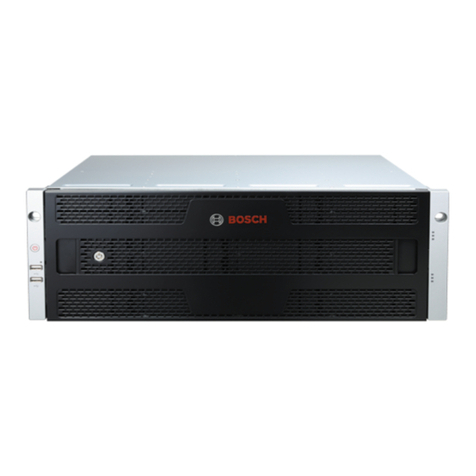
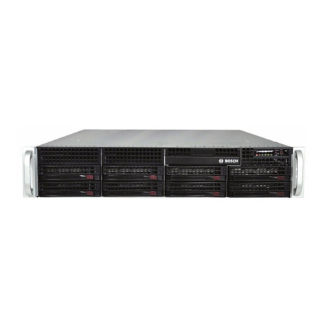
Bosch DSA E Series User manual

E2600 DSA E-Series iSCSI Disk Arrays
en Installation Manual


E2600 DSA E-Series iSCSI Disk Arrays Table of Contents | en 3
Bosch Security Systems Installation Manual - | V2 | 2012.09
Table of Contents
1 Safety Precautions 6
1.1 Warning Notices 6
1.2 Caution Notices 9
2 Preparing for an E2600 Controller-Drive Tray Installation 11
2.1 Key Terms 12
2.2 Gathering Items 12
2.2.1 Basic Hardware 13
2.2.2 Tools and Other Items 17
2.2.3 Things to Know – SFP Transceivers, Fiber-Optic Cables, Copper Cables, and SAS Cables 17
2.2.4 Things to Know – Taking a Quick Glance at the Hardware 19
3 Installing and Configuring the Switches 27
3.1 Things to Know – Switches 27
3.2 Procedure – Installing and Configuring Switches 29
4 Installing the Host Bus Adapters for the E2600 Controller-Drive Tray 30
4.1 Key Terms 30
4.2 Things to Know – Host Bus Adapters and Ethernet Network Interface Cards 30
4.3 Procedure – Installing Host Bus Adapters 31
5 Installing the E2600 Controller-Drive Tray 32
5.1 Things to Know – General Installation 32
5.2 Procedure – Installing the E2600 Controller-Drive Tray 32
6 Connecting the E2600 Controller-Drive Tray to the Hosts 35
6.1 Key Terms 35
6.2 Things to Know – Host Channels 35
6.3 Procedure – Connecting Host Cables on an E2600 Controller-Drive Tray 36
6.4 Example cabling patterns 37
6.4.1 Direct Topology – One Host Connected to a SingleController 37
6.4.2 Direct Topology – Two Hosts Connected to a Single Controller 38
6.4.3 Switch Topology – Two Hosts Connected to a Single Controller Through a Switch 39
6.4.4 Direct Topology – One Host and a Dual Controller-Drive Tray 40
6.4.5 Direct Topology – Two Hosts and a Dual Controller-Drive Tray for Maximum Redundancy 41
6.4.6 Mixed Topology – Two Hosts and a Dual Controller-Drive Tray 42
6.4.7 Mixed Topology – Three Hosts and a Dual Controller-Drive Tray 43
7 Installing the Drive Trays for the E2600 Controller-Drive Tray Configurations 44
7.1 Things to Know – General Installation of Drive Trays with the E2600 Controller-Drive Tray 44
7.2 For Additional Information on Drive Tray Installation 44
7.3 Procedure – Installing the DE1600 Drive Trays 44
7.4 Procedure – Installing Drives in the DE1600 Drive Trays 51

4en | Table of Contents E2600 DSA E-Series iSCSI Disk Arrays
- | V2 | 2012.09 Installation Manual Bosch Security Systems
8 Connecting the E2600 Controller-Drive Tray to the Drive Trays 53
8.1 Key Terms 53
8.2 Things to Know – E2600 Controller-Drive Tray 53
8.3 Things to Know – Drive Trays with the E2600 Controller-Drive Tray 53
8.4 Things to Know – Drive Tray Cabling Configurations – Simplex System 54
8.5 Things to Know – Drive Tray Cabling Configurations – Duplex System 55
8.6 Procedure – Connecting the DE1600 Drive Trays 57
9 Connecting the Ethernet Cables 60
9.1 Key Terms 60
9.2 Things to Know – Connecting Ethernet Cables 60
9.3 Procedure – Connecting Ethernet Cables 60
10 Connecting the Power Cords 61
10.1 Things to Know – AC Power Cords 61
10.2 Things to Know – DC Power Cords 61
10.3 Procedure – Connecting AC Power Cords 62
10.4 Procedure – Connecting DC Power Cords 62
11 Turning on the Power and Checking for Problems 64
11.1 Turning On the Power to the Storage Array and Checking for Problems 64
11.2 Things to Know – LEDs on the E2600 Controller-Drive Tray 64
11.3 Things to Know – General Behavior of the LEDs on the E2600 Controller-Drive Tray 71
11.4 Things to Know – LEDs on the DE1600 Drive Tray 74
11.5 General Behavior of the LEDs on the DE1600 79
11.6 Things to Know – Service Action Allowed LEDs 81
11.7 Things to Know – Sequence Code Definitions for the E2600 Controller-Drive Tray 82
11.8 Things to Know – Lock-Down Codes for the E2600 Controller-Drive Tray 82
11.9 Things to Know – Diagnostic Code Sequences for the E2600 Controller-Drive Tray 84
11.10 Things to Know – Seven-Segment Display for the DE1600 Drive Tray 85
12 Replacing a Drive in an E2600 Controller-Drive Tray 86
13 Replacing a Controller Canister in the Controller-Drive Tray 90
13.1 Removing a Controller Canister from the Controller-Drive Tray 90
13.2 Installing a Controller Canister in the Controller-Drive Tray 96
14 Replacing a Controller Battery in the Controller-Drive Tray 98
15 Replacing a Power-Fan Canister in the Controller-Drive Tray 104
15.1 Replacing an AC Power-Fan Canister in the Controller-Drive Tray 104
15.2 Replacing a DC Power-Fan Canister in the Controller-Drive Tray 107
16 Upgrading or Replacing a Host Interface Card in the Controller-Drive Tray 111
16.1 Removing the Host Interface Card from the Controller-Drive Tray 111
16.2 Installing the Host Interface Card in the Controller-Drive Tray 116
E2600 DSA E-Series iSCSI Disk Arrays Table of Contents | en 5
Bosch Security Systems Installation Manual - | V2 | 2012.09
17 Replacing a Controller Canister and Related Components 119
17.1 Removing a Controller Canister from the Controller-Drive Tray 119
17.2 Replacing the Host Interface Card in the Controller-Drive Tray 124
17.3 Removing the Cache Memory DIMM from and Reinstalling It into the Controller-Drive Tray 125
17.4 Removing and Installing the Cache Memory Offload Backup SD Card 127
17.5 Removing a Controller Battery from and Reinstalling It into the Controller-Drive Tray 127
17.6 Reinstalling a Controller Canister in the Controller-Drive Tray 128
18 Replacing Failed Memory in the E2600 Controller Canister 130
18.1 Removing a Controller Canister from the E2600 Controller-Drive Tray 130
18.1.1 Cache Memory DIMM Fault Code / Display Error Code Definitions 134
18.2 Replacing a Cache Memory DIMM 135
18.3 Replacing a Cache Backup Memory Device 136
18.4 Reinstalling the Controller Canister in the E2600 Controller-Drive Tray 137
18.5 Bringing the Controller Canister Online 138
19 Upgrading Memory in the E2600 Controller Canisters 139
19.1 Removing the Controller Canisters from the E2600 Controller-Drive Tray 139
19.2 Upgrading the Cache Memory DIMM 142
19.3 Upgrading the Cache Backup Memory Device 144
19.4 Reinstalling the Controller Canister in the E2600 Controller-Drive Tray 144
19.5 Turning On Power to the Controller Canisters in the E2600 Controller-Drive Tray 145
20 Regulatory Compliance Statements 147
20.1 FCC Radio Frequency Interference Statement 147
20.2 Laser Products Statement 147

6en | Safety Precautions E2600 DSA E-Series iSCSI Disk Arrays
- | V2 | 2012.09 Installation Manual Bosch Security Systems
1 Safety Precautions
Definitions of safety notices:
– WARNING indicates a poptentially hazadous situation that could result in death or severe
personal injury.
– CAUTION indicates a potentially hazardous situation that could result in moderate or
minor personal injury.
1.1 Warning Notices
WARNING!
Risk of electrical shock
If there is evidence of fire, water, or structural damage, never turn on the power to the
equipment.
WARNING!
Risk of electrical shock
Before removing or installing a power supply, turn off the power switch, and unplug the power
cord.
WARNING!
Risk of exposure to laser radiation
Do not disassemble or remove any part of a Small Form-factor Pluggable (SFP) transceiver
because you might be exposed to laser radiation.
WARNING!
Risk of bodily injury
The battery can weigh up to 10.9 kg (24 lb). When you remove the battery, be prepared to
support its weight. If the battery is dropped, the impact might cause bodily injury, including
deep puncture wounds caused by the battery pins.
WARNING!
Risk of bodily injury
If the bottom half of the cabinet is empty, do not install components in the top half of the
cabinet. If the top half of the cabinet is too heavy for the bottom half, the cabinet might fall
and cause bodily injury. Always install a component in the lowest available position in the
cabinet.
WARNING!
Risk of bodily injury
Attach the stability foot before moving the cabinet. If you do not attach the stability foot, the
cabinet might become unstable, or it might fall. This problem is most likely to occur when the
cabinet is moved along inclined surfaces or over uneven surfaces.

E2600 DSA E-Series iSCSI Disk Arrays Safety Precautions | en 7
Bosch Security Systems Installation Manual - | V2 | 2012.09
WARNING!
Risk of bodily injury
Only move a populated cabinet with a forklift or adequate help from other persons. Always
push the cabinet from the front to prevent it from falling over.
A fully populated cabinet can weigh more than 909 kg (2000 lb). The cabinet is difficult to
move, even on a flat surface. If you must move the cabinet along an inclined surface, remove
the components from the top half of the cabinet, and make sure that you have adequate help.
WARNING!
Risk of bodily injury
Two persons are required to safely lift the component.
,
WARNING!
Risk of bodily injury
Three persons are required to safely lift the component.
,
WARNING!
Risk of bodily injury
Four or more persons are required to safely lift the component.
,
WARNING!
Risk of fire or chemical burn
Before disposing of a used battery, review the battery warning label. The label reads: The
battery used in this device may present a risk of fire or chemical burn if mistreated. DO NOT
disassemble, heat above 60ºC (140ºF), crush or puncture, short circuit external contacts, or
dispose of in fire or water. Use LSI recommended charger only. Replace only with original LSI
batteries.

8en | Safety Precautions E2600 DSA E-Series iSCSI Disk Arrays
- | V2 | 2012.09 Installation Manual Bosch Security Systems
WARNING!
Risk of electrical shock
1 - Supply (Negative), Brown Wire, -48 VDC
2 - Return (Positive), Blue Wire
3 - Ground, Green/Yellow Wire
4 - DC Power Connector
This unit has more than one power source. To remove all power from the unit, all DC MAINS
must be disconnected by removing all power connectors (item 4 below) from the power
supplies.
WARNING!
Risk of bodily injury
Only move a populated cabinet with a forklift or adequate help from other persons. Attach the
stability foot before moving the cabinet. If you do not attach the stability foot, the cabinet
might become unstable, or it might fall. Always push the cabinet from the front to prevent it
from falling over.
A fully populated cabinet can weigh more than 636 kg (1420 lb). The cabinet is difficult to
move, even on a flat surface. If you must move the cabinet along an inclined surface, remove
the components from the top half of the cabinet, and make sure that you have adequate help.
WARNING!
Risk of bodily injury
A qualified service person is required to make the DC power connection according to NEC and
CEC guidelines.
WARNING!
Risk of bodily injury
An empty tray weighs approximately 56.7 kg (125 lb). Three persons are required to safely
move an empty tray. If the tray is populated with components, a mechanized lift is required to
safely move the tray.

E2600 DSA E-Series iSCSI Disk Arrays Safety Precautions | en 9
Bosch Security Systems Installation Manual - | V2 | 2012.09
1.2 Caution Notices
WARNING!
Risk of bodily injury
Each tray has more than one power cord. To remove all electrical current from the devices,
make sure that all of the power cords are disconnected from the power source and that the
two-pole 20-amp circuit breaker for the storage array has been disconnected.
WARNING!
Risk of bodily injury
Each tray has more than one power cord. To remove all electrical current from the devices,
make sure that all of the power cords are disconnected from the power source.
WARNING!
Risk of bodily injury
Do not use equipment in the cabinet as a shelf or work space.
CAUTION!
Potentially hazardous material
The battery pack contains sealed lead acid batteries that might be considered hazardous
material. If you recycle a used battery pack that is not damaged, use the proper facilities.
Handle the battery pack according to all applicable regulations.
CAUTION!
Potentially hazardous material
If the used battery pack is physically damaged or is leaking, DO NOT ship the battery pack to a
recycling center. Handling a damaged battery pack exposes you and others to potentially
hazardous material. Dispose of the damaged battery pack according to all applicable
regulations.
CAUTION!
Pinching hazard
As you push the canister into the slot, ensure that your fingers are not pinched between the
lever and the canister. The lever automatically moves toward the closed position as the
canister is pushed into its slot.

10 en | Safety Precautions E2600 DSA E-Series iSCSI Disk Arrays
- | V2 | 2012.09 Installation Manual Bosch Security Systems
CAUTION!
Potentially hazardous material
The battery pack contains sealed lithium ion batteries that might be considered hazardous
material. If the used battery pack is physically damaged and is leaking, DO NOT ship the
battery pack to a recycling center. Handling a damaged battery pack exposes you and others
to potentially hazardous material. Dispose of the damaged battery pack according to all
applicable regulations. If you recycle a used battery pack that is not damaged, use the proper
facilities. Handle the battery pack according to all applicable regulations.
CAUTION!
Electrical grounding hazard
This equipment is designed to permit the connection of the DC supply circuit to the earthing
conductor at the equipment.
CAUTION!
Possible hazard exists
Do not remove more than one canister from the enclosure while power to the enclosure is
turned on.

E2600 DSA E-Series iSCSI Disk Arrays Preparing for an E2600 Controller-Drive Tray Installation | en 11
Bosch Security Systems Installation Manual - | V2 | 2012.09
2 Preparing for an E2600 Controller-Drive Tray
Installation
Storage arrays for 6-Gb/s SAS drives consist of an E2600 controller-drive tray and one or more
DE1600 drive trays in a cabinet:
Use this document to install the E2600 controller-drive trays and all necessary drive trays for
your configuration.
The following table shows the various configuration options.
Table 2.1 E2600 Controller-Drive Tray Options
E2600 Configurations Options
Simplex (one controller)
E2600 controller-drive tray
with no host interface card
A maximum of 96 drives that you can upgrade to 192. The
upgrade is a Premium feature.
Any combination of E2600 controller-drive trays attached to
DE1600 drive trays, not to exceed a maximum of 96 (or 192)
drive slots in the storage array.
Two 6-Gb/s host connectors.
8-GB battery backup.
Simplex E2600 controller-
drive tray with a host
interface card
A maximum of 96 drives that you can upgrade to 192. The
upgrade is a Premium feature.
Any combination of E2600 controller-drive trays attached to
DE1600 drive trays, not to exceed a maximum of 96 (or 192)
drive slots in the storage array.
Two 6-Gb/s host connectors, in addition to one of the
following host interface cards:
– Two 6-Gb/s SAS connectors
– Four 1-Gb/s iSCSI connectors
– Two 10-Gb/s iSCSI connectors
– Four 8-Gb/s Fibre Channel (FC) connectors
8-GB battery backup.
Duplex (two controllers)
E2600 controller-drive tray
without a host interface card
A maximum of 96 drives that you can upgrade to 192. The
upgrade is a Premium feature.
Any combination of E2600 controller-drive trays attached to
DE1600 drive trays, not to exceed a maximum of 96 (or 192)
drive slots in the storage array.
Two 6-Gb/s host connectors.
8-GB battery backup.
Duplex E2600 controller-
drive tray with a host
interface card
A maximum of 96 drives that you can upgrade to 192. The
upgrade is a Premium feature.
Any combination of E2600 controller-drive trays attached to
DE1600 drive trays, not to exceed a maximum of 96 (or 192)
drive slots in the storage array.
Two 6-Gb/s host connectors, in addition to one of the
following host interface cards:
– Two 6-Gb/s SAS connectors
– Four 1-Gb/s iSCSI connectors
– Two 10-Gb/s iSCSI connectors
– Four 8-Gb/s FC connectors
8-GB battery backup.

12 en | Preparing for an E2600 Controller-Drive Tray Installation E2600 DSA E-Series iSCSI Disk Arrays
- | V2 | 2012.09 Installation Manual Bosch Security Systems
2.1 Key Terms
storage array
A collection of both physical components and logical components for storing data. Physical
components include drives, controllers, fans, and power supplies. Logical components
include volume groups and volumes. These components are managed by the storage
management software.
controller-drive tray
One tray with drives, one or two controllers, fans, and power supplies. The controller-drive
tray provides the interface between a host and a storage array.
controller
A circuit board and firmware that is located within a controller tray or a controller-drive tray. A
controller manages the input/output (I/O) between the host system and data volumes.
drive tray
One tray with drives, one or two environmental services monitors (ESMs), power supplies,
and fans. A drive tray does not contain controllers.
environmental services monitor (ESM)
A canister in the drive tray that monitors the status of the components. An ESM also serves as
the connection point to transfer data between the drive tray and the controller.
Small Form-factor Pluggable (SFP) transceiver
A component that enables Fibre Channel duplex communication between storage array
devices. SFP transceivers can be inserted into host bus adapters (HBAs), controllers, and
environmental services monitors (ESMs). SFP transceivers can support either copper cables
(the SFP transceiver is integrated with the cable) or fiber-optic cables (the SFP transceiver is
a separate component from the fiber-optic cable).
2.2 Gathering Items
Before you start installing the controller-drive tray, you must have installed the cabinet in
which the controller-drive tray will be mounted.
Use the tables in this section to verify that you have all of the necessary items to install the
controller-drive tray.
CAUTION!
Possible hardware damage
To prevent electrostatic discharge damage to the tray, use proper antistatic protection when
handling tray components.

E2600 DSA E-Series iSCSI Disk Arrays Preparing for an E2600 Controller-Drive Tray Installation | en 13
Bosch Security Systems Installation Manual - | V2 | 2012.09
2.2.1 Basic Hardware
Table 2.2 Basic Hardware
Item Included with the
Controller-Drive
Tray
Cabinet
– Make sure that your cabinet meets the
installation site specifications of the
various E2600 storage array
components. Refer to the Storage
System Site Preparation Guide for
more information.
– Depending on the power supply
limitations of your cabinet, you might
need to install more than one cabinet
to accommodate the different
components of the E2600 storage
array. .
DE1600 drive tray with end caps that are
packaged separately.
Yes
Mounting rails and screws
The mounting rails that are available with
the drive tray are designed for an industry-
standard cabinet.
Fibre Channel switch (optional)
SAS switch (optional)
Gigabit Ethernet switch (optional)
– Host with Fibre Channel host bus
adapters (HBAs) (optional)
– Host with iSCSI HBAs (optional) or a
network interface card (optional)
– Host with SAS HBAs (optional)

14 en | Preparing for an E2600 Controller-Drive Tray Installation E2600 DSA E-Series iSCSI Disk Arrays
- | V2 | 2012.09 Installation Manual Bosch Security Systems
Table 2.3 Cables and Connectors
Item Included with the
Controller-Drive
Tray or Drive Trays
AC power cords.
The controller-drive tray and the drive trays
ship with power cords for connecting to an
external power source, such as a wall plug.
Your cabinet might have special power
cords that you use instead of the power
cords that ship with the controller-drive
tray and the drive trays.
Yes
(Optional) Two DC power connector cables
are provided with each drive tray for
connection to centralized DC power plant
equipment.
– Four DC power connector cables are
provided if additional redundancy is
required.
–A qualified service person is required
to make the DC power connection per
NEC and CEC guidelines. A two-pole
20-amp circuit breaker is required
between the DC power source and the
drive tray for over-current and short-
circuit protection. Before turning off
any power switches on a DC-powered
drive tray, first you must disconnect
the two-pole 20-amp circuit breaker.
Yes
For the DC power
option only
Copper SAS cables - Use for all drive-side
connections within the storage array.
Fiber-optic cables - Use for FC connections
to the drive trays.
For the differences between the fiber-optic
cables and the copper Fibre Channel (FC)
cables, see Section 2.2.3 Things to Know –
SFP Transceivers, Fiber-Optic Cables, Copper
Cables, and SAS Cables, page 17

E2600 DSA E-Series iSCSI Disk Arrays Preparing for an E2600 Controller-Drive Tray Installation | en 15
Bosch Security Systems Installation Manual - | V2 | 2012.09
Small Form-factor Pluggable (SFP)
transceivers
– The SFP transceivers connect fiber-
optic cables to host ports and drive
ports.
– Four or eight SFP transceivers are
included with the controller-drive tray;
one for each of the host channel ports
on the controllers.
– Depending on your connection
requirements, you might need to
purchase additional SFP transceivers
(two SFP transceivers for each fiber-
optic cable).
– Depending on the configuration of your
storage array, you might need to use
various combinations of four different
types of SFP transceivers: 8-Gb/s Fibre
Channel, 6-Gb/s SAS, 1-Gb/s iSCSI, or
10-Gb/s iSCSI. These SFP transceivers
are not generally interchangeable.
– You must purchase only Restriction of
Hazardous Substances (RoHS)-
compliant SFP transceivers.
Copper Fibre Channel cables (optional)
Use these cables for connections within the
storage array.
For the differences between the fiber-optic
cables and the copper Fibre Channel
cables, see Section 2.2.3 Things to Know –
SFP Transceivers, Fiber-Optic Cables, Copper
Cables, and SAS Cables, page 17
Yes
Ethernet cable
This cable is used for out-of-band storage
array management and for 1-Gb/s iSCSI
connections.
Table 2.3 Cables and Connectors
Item Included with the
Controller-Drive
Tray or Drive Trays

16 en | Preparing for an E2600 Controller-Drive Tray Installation E2600 DSA E-Series iSCSI Disk Arrays
- | V2 | 2012.09 Installation Manual Bosch Security Systems
SAS cables
The SAS cables connect the host to the
controller-drive tray. If you install a drive
tray, you must use SAS cables to connect
the controller-drive tray to the drive tray.
Serial cable
This cable is used for support only. You do
not need to connect it during initial
installation.
DB9-to-PS2 adapter cable
This cable adapts the DB9 connector on
commercially available serial cables to the
PS2 connector on the controller.
Table 2.4 Product DVDs
Item Included with the
Controller-Drive
Tray
Firmware DVD
– Firmware is already installed on the
controllers.
– The files on the DVD are backup
copies.
SANtricity ES Storage Manager Installation
DVD
– SANtricity ES Storage Manager
software and documentation.
– To access product documentation, use
the documentation map file,
doc_launcher.html, which is located in
the docs directory.
Yes
Table 2.3 Cables and Connectors
Item Included with the
Controller-Drive
Tray or Drive Trays

E2600 DSA E-Series iSCSI Disk Arrays Preparing for an E2600 Controller-Drive Tray Installation | en 17
Bosch Security Systems Installation Manual - | V2 | 2012.09
2.2.2 Tools and Other Items
2.2.3 Things to Know – SFP Transceivers, Fiber-Optic Cables, Copper Cables,
and SAS Cables
The figures in this topic display the fiber-optic cables, copper cables, SFP transceivers., and
SAS cables with a SFF-8088 Connector.
Table 2.5 Tools and Other Items
Item Included with the
Tray
Labels
Help you to identify cable connections and
lets you more easily trace cables from one
tray to another
A cart
Holds the tray and components
A mechanical lift (optional)
Use the Compatibility Matrix, at the following website, to obtain the latest hardware
compatibility information:
NOTICE!
Your SFP transceivers and cables might look slightly different from the ones shown. The
differences do not affect the performance of the SFP transceivers.

18 en | Preparing for an E2600 Controller-Drive Tray Installation E2600 DSA E-Series iSCSI Disk Arrays
- | V2 | 2012.09 Installation Manual Bosch Security Systems
The controller-drive tray supports SAS, Fibre Channel (FC), and iSCSI host connections and
SAS drive connections. FC host connections can operate at 8 Gb/s or at a lower data rate.
Ports for 8-Gb/s Fibre Channel host connections require SFP transceivers designed for this
data rate. These SFP transceivers look similar to other SFP transceivers but are not
compatible with other types of connections. SFP transceivers for 1-Gb/s iSCSI and 10-Gb/s
iSCSI connections have a different physical interface for the cable and are not compatible
with other types of connections.
Figure 2.1 Fiber-Optic Cable Connection
Figure 2.2 1-Gb/s iSCSI Cable Connection
Figure 2.3 Copper Fibre Channel Cable Connection
WARNING!
Risk of exposure to laser radiation
Do not disassemble or remove any part of a Small Form-factor Pluggable (SFP) transceiver
because you might be exposed to laser radiation.
1Active SFP Transceiver
2Fiber-Optic Cable
1Active SFP Transceiver
2Copper Cable with RJ-45 Connector
1Copper Fibre Channel Cable
2Passive SFP Transceiver

E2600 DSA E-Series iSCSI Disk Arrays Preparing for an E2600 Controller-Drive Tray Installation | en 19
Bosch Security Systems Installation Manual - | V2 | 2012.09
Figure 2.4 SAS Cable Connection
2.2.4 Things to Know – Taking a Quick Glance at the Hardware
– The top of the controller-drive tray is the side with labels.
– The configuration of the host ports might appear different on your system depending on
which host interface card configuration is installed.
Figure 2.5 E2600 Controller-Drive Tray with 12 Drives – Front View
1SAS Cable
2SFF-8088 Connector
WARNING!
Risk of bodily injury
A qualified service person is required to make the DC power connection according to NEC and
CEC guidelines.
CAUTION!
Electrical grounding hazard
This equipment is designed to permit the connection of the DC supply circuit to the earthing
conductor at the equipment.
NOTICE!
Each tray in the storage array must have a minimum of two drives for proper operation. If the
tray has fewer than two drives, a power supply error is reported.
1End Cap Standby Power LED
2End Cap Power LED
3End Cap Over-Temperature LED
4End Cap Service Action Required LED
5End Cap Locate LED
6Drive Canister

20 en | Preparing for an E2600 Controller-Drive Tray Installation E2600 DSA E-Series iSCSI Disk Arrays
- | V2 | 2012.09 Installation Manual Bosch Security Systems
Figure 2.6 E2600 Controller-Drive Tray Duplex Configuration– Rear View
1Controller A Canister
2Seven-Segment Display
3Host Interface Card Connector 1
4Host Interface Card Connector 2
5Serial Connector
6Ethernet Connector 1
7Ethernet Link Active LED
8Ethernet Link Rate LED
9Ethernet Connector 2
10 Host SFF-8088 Connector 2 (Native)
11 Host Link 2 Fault LED
12 Host Link 2 Active LED
13 Base Host SFF-8088 Connector 1
14 ESM Expansion Fault LED
15 ESM Expansion Active LED
16 Expansion SFF-8088 Port Connector
17 Power-Fan Canister
18 Standby Power LED
19 Power-Fan DC Power LED
20 Power-Fan Service Action Allowed LED
21 Power-Fan Service Action Required LED
22 Power-Fan AC Power Connector and Switch
23 Power-Fan DC Power Connector and Switch
Other manuals for DSA E Series
1
This manual suits for next models
1
Table of contents
Other Bosch Storage manuals

Bosch
Bosch DIVAR IP 6000 (2U) User manual

Bosch
Bosch 1200 Series User manual

Bosch
Bosch 1200 Series IP User manual

Bosch
Bosch DVAS User manual

Bosch
Bosch DVA-12T User manual

Bosch
Bosch DVA-12T User manual

Bosch
Bosch CIP5000 Series User manual

Bosch
Bosch CIP5000 Series User manual

Bosch
Bosch DVA-08K User manual
Popular Storage manuals by other brands

Olympus
Olympus S-HD-100 user manual

Kingston Technology
Kingston Technology DataTraveler Vault-Privacy user manual

MicroNet
MicroNet RAIDBANK 5 owner's guide

Overland Tandberg
Overland Tandberg NEO Series Upgrade guide

TerraMaster
TerraMaster TNAS F5-420 Fundamentals and Preliminaries

HP
HP StoreEver ESL G3 specification