4/16 HED 8 | Pressure Switch
Bosch Rexroth AG, RE 50061, edition: 2016-09
Technical data
(For applications outside these parameters, please consult us!)
Hydraulic
Pressure rating bar 50 100 200 350 630
Max. operating pressure
Conformity ▶ NBR/FKM seals bar 350 350 350 400 630
▶ MT version bar 315 315 315 315 –
Pressure adjustment range (decreasing) bar 5...50 10...100 15...200 25...350 40...630
Pressure differential per rotation 1) bar ≈19 ≈35 ≈77 ≈120 ≈214
Hydraulic fluid 1) see table below
Hydraulic fluid temperature range
(at the valve operating ports)
°C -25 ... +80 (NBR seals)
-20 ... +80 (FKM seals)
-40 … +80 (low-temperature seals)
Viscosity range mm2/s 10 … 800
Maximum permissible degree of contamination of the hy-
draulic fluid, cleanliness class according to ISO 4406 (c)
Class 20/18/15 2)
Load cycles ≥ 5 million
General
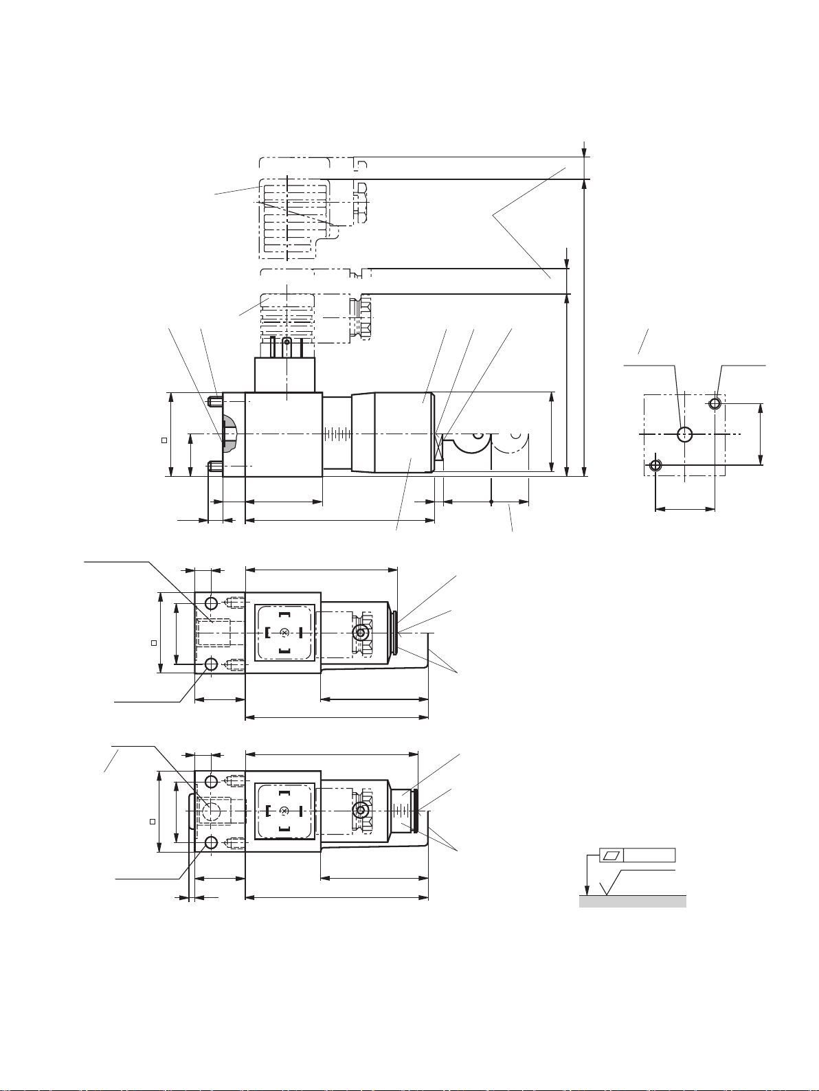
Mass kg 0.8
Installation position any
Ambient temperature range °C -25 to +50 (NBR seals)
-20 to +50 (FKM seals)
-40 to +50 (low-temperature seals)
Sine test according to DIN EN 60068-2-6:1996-05 5...2000 Hz, max. 10 g, 10 double cycles
Transport shock according to DIN EN 60068-2-27:1995-03 15 g / 11 ms
Bump test according to DIN EN 60068-2-29:1995-03 25 g / 6 ms
Noise test according to DIN EN 60068-2-64:1996-05 20...2000 Hz 10...30 min
Conformity ▶ CE DIN EN 61058-1: 2002 / A2: 2008
DIN EN 60947-1: 2007 / A1: 2011
DIN EN 60947-5-1: 2004 / A1: 2009
DIN EN 60529: 1991 / A2: 2013
▶ UL UL 508 17th edition File No E223220 (up to 350 bar)
▶ CCC GB 14048.5-2008
Hydraulic fluid Classification Suitable
sealing materials
Standards Data sheet
Mineral base oils HL, HLP, HLPD, HVLP, HVLPD NBR, FKM low-temperature
seals
DIN 51524 90220
Bio-degradable ▶ Insoluble in water HETG NBR, FKM ISO15380 90221
HEES FKM
▶ Soluble in water HEPG FKM ISO15380
Flame-resistant ▶ Water-free HFDU, HFDR FKM ISO 12922 90222
▶ Containing water HFC (Fuchs Hydrotherm 46M,
Petrofer Ultra Safe 620)
NBR ISO 12922 90223
Important information on hydraulic fluids:
▶ For more information and data about the use of other hydraulic
fluids, refer to data sheets above or contact us!
▶ There may be limitations regarding the technical data (tempera-
ture, pressure range, life cycle, maintenance intervals, etc.).
▶ Flame-resistant – contains water:
– Maximum pressure differential per control edge 50bar
– Pressure pre-loading at the tank port > 20% of the pressure
differential, otherwise increased cavitation
– Life cycle as compared to operation with mineral oil HL,
HLP 50 to 100%
▶ Bio-degradable and flame-resistant: When using these hydraulic
fluids that are simultaneously zinc-solving, zinc may accumulate
(700mg zinc per pole tube).