manuals.online logo
Brands
  1. Home
  2. •
  3. Brands
  4. •
  5. Bosch
  6. •
  7. TV Mount
  8. •
  9. Bosch rexroth NYA04.1-STRAIN-RELIEF-4150-NY4901/40 User manual

Bosch rexroth NYA04.1-STRAIN-RELIEF-4150-NY4901/40 User manual

R911404771-01_BAL_DOC
December 7, 2020
Page 1 of 5
1 About this documentation
1.1 Overview – target groups & product phases
The target groups, product phases and activities that can
refer to this document are marked in rounded boxes in
the following figure.
Selection Mounting
(assembly/installation)
Engineering
Commissioning
Operation
De-commissioning
Product phases
Presales Aftersales
Design engineer
Programmer
Technologist
specialist
Mechanic/
electrician
Process
Commissioning engineer
Programmer
Technologist
Process specialist
Machine
operator
Maintenance
technician
Service
Mechanic/
electrician
Disposal company
To select
To prepare
To design
To construct
To unpack
To mount
To install
To parameterize
To program
To configure
To simulate
To optimize
To test
To operate
To maintain
To remove
faults
To create
the program
To dismount
To dispose
Target groups
Activities
1.2 Intended audience
This document explains technical and service personnel of
the machine builder how to safely install the cable strain
relief bracket on the NY4150/10 module. This document is
not the usage manual.
1.3 Availability
These instructions are part of the cable strain relief
bracket product delivery and must always be available for
the user. If the cable strain relief bracket is handed over
to another person, these instructions must be handed
over as well.
1.4 Included parts
1.5 Variations
These instructions apply to the cable strain relief bracket
with the following Type code:
•NYA04.1-STRAIN-RELIEF-4150-NY4901/40
1.6 Further available documentation
1.7 Additional parts
System housings, drive modules, connection cables, and
more are listed in the project planning manuals or on
www.boschrexroth.com.
2 Product Identification and Scope of Delivery
2.1 Product identification
Figure 1. View of the NYA04.1-STRAIN-RELIEF-4150-NY4901/40
The NYA04.1-STRAIN-RELIEF-4150-NY4901/40 can be iden-
tified by the label on the top side of the bracket.
BOSCH REXROTH AG
BGM.-DR.-NEBELSTR. 2
97816 LOHR, GERMANY
MNR:
R911403465 - AA
7261 Made in Germany
123
5 4
1 Company address
2 Material number
3 Version level and status
4 Designation of origin
5 Division number / plant number
2.2 Scope of delivery
The NYA04.1-STRAIN-RELIEF-4150-NY4901/40 product de-
livery consists of the following items.
•NYA04.1-STRAIN-RELIEF-4150-NY4901/40 cable strain
relief bracket for the NY4150/10 module, material
number R911403465.
•DOK-NY4000-STRNY490140-IT01-EN-P Instructions,
material number R911404771.
3 Using the Safety Instructions
3.1 Safety instructions - structure
The safety instructions are structured as follows.
3.2 Explaining signal words and safety alert symbol
The safety instructions in this documentation contain spe-
cific signal words (danger, warning, caution, notice) and,
if necessary, a safety alert symbol (according to ANSI
Z535.6-2006).
The signal word is meant to draw the reader’s attention to
the safety instruction and signifies the degree of danger.
Title and type code
Material number
Rexroth NYCe 4000 Hardware System Manual
DOK-NY4000-HW***SYSTEM-PRRS-EN-E R911337671
Rexroth NYCe 4000 Standard Housings & Accessories Manual
DOK-NY4000-HOUSING*ACC-PRRS-EN-E R911337672
Type code
Material number
Description
NYA04.1-STRAIN-RELIEF-4150-NY4901/40 R911403465 Cable bracket
DOK-NY4000-STRNY490140-IT01-EN-P
R911404771
Instructions
EN
Instructions
Rexroth
NYA04.1-STRAIN-RELIEF-4150-NY4901/40
Bosch Rexroth AG
P.O. Box 13 57
97803 Lohr a.Main, Germany
Bgm.-Dr.-Nebel-Str. 2
97816 Lohr a.Main, Germany
Tel. +49 9352 18 0
Fax +49 9352 18 8400
www.boschrexroth.com/electrics
R911404771-01_BAL_DOC
December 7, 2020
Page 2 of 5
The safety alert symbol (a triangle with an exclamation
point), which precedes the signal words danger, warning
and caution is used to alert the reader to personal injury
hazards.
_________________________________________________________________
In case of non-compliance with this safety instruction,
death or serious injury will occur.
_________________________________________________________________________________________________
_________________________________________________________________
In case of non-compliance with this safety instruction,
death or serious injury can occur.
_________________________________________________________________________________________________
_________________________________________________________________
In case of non-compliance with this safety instruction,
minor or moderate injury could occur.
_________________________________________________________________________________________________
_________________________________________________________________
In case of non-compliance with this safety instruction,
property damage could occur.
_________________________________________________________________________________________________
4 Intended Use
The cable strain relief bracket is for indoor use only, and
may only be used with parts indicated in this document.
Not explicitly mentioned parts may not be installed or
connected. Usage is only allowed in explicitly indicated
combinations of parts.
Do not install and use this cable strain relief bracket
before you have read all relevant documents. You must
read the safety instructions and all other directions for
use before you start any work or activity with this cable
strain relief bracket.
5 Accessories, Spare Parts and Wear Parts
The cable strain relief bracket does not contain any re-
placeable or wear parts. In case of failure, the entire cable
strain relief bracket must be replaced.
6 Ambient Conditions
7 Standards
7.1 CE marking
Declaration of Conformity
The cable strain relief bracket installed on the NY4150/10
module complies with the requirements and the target of
the following EU directive.
EMC Directive
•2014/30/EU
The cable strain relief bracket detached from the module
has no reference to a directive.
7.2 China RoHS 2 marking
The NYA04.1-STRAIN-RELIEF-4150-NY4901/40 complies
with the requirements of the Administrative Measures for
the Restriction of the Use of Hazardous Substances in
Electrical and Electronic Products, known as China RoHS
2.
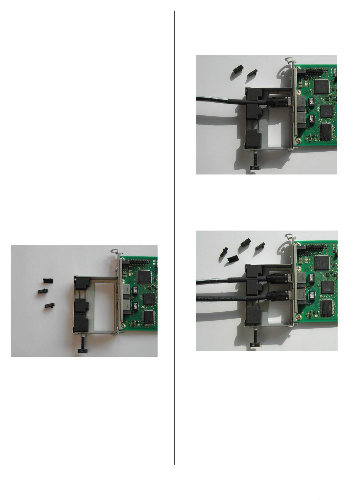
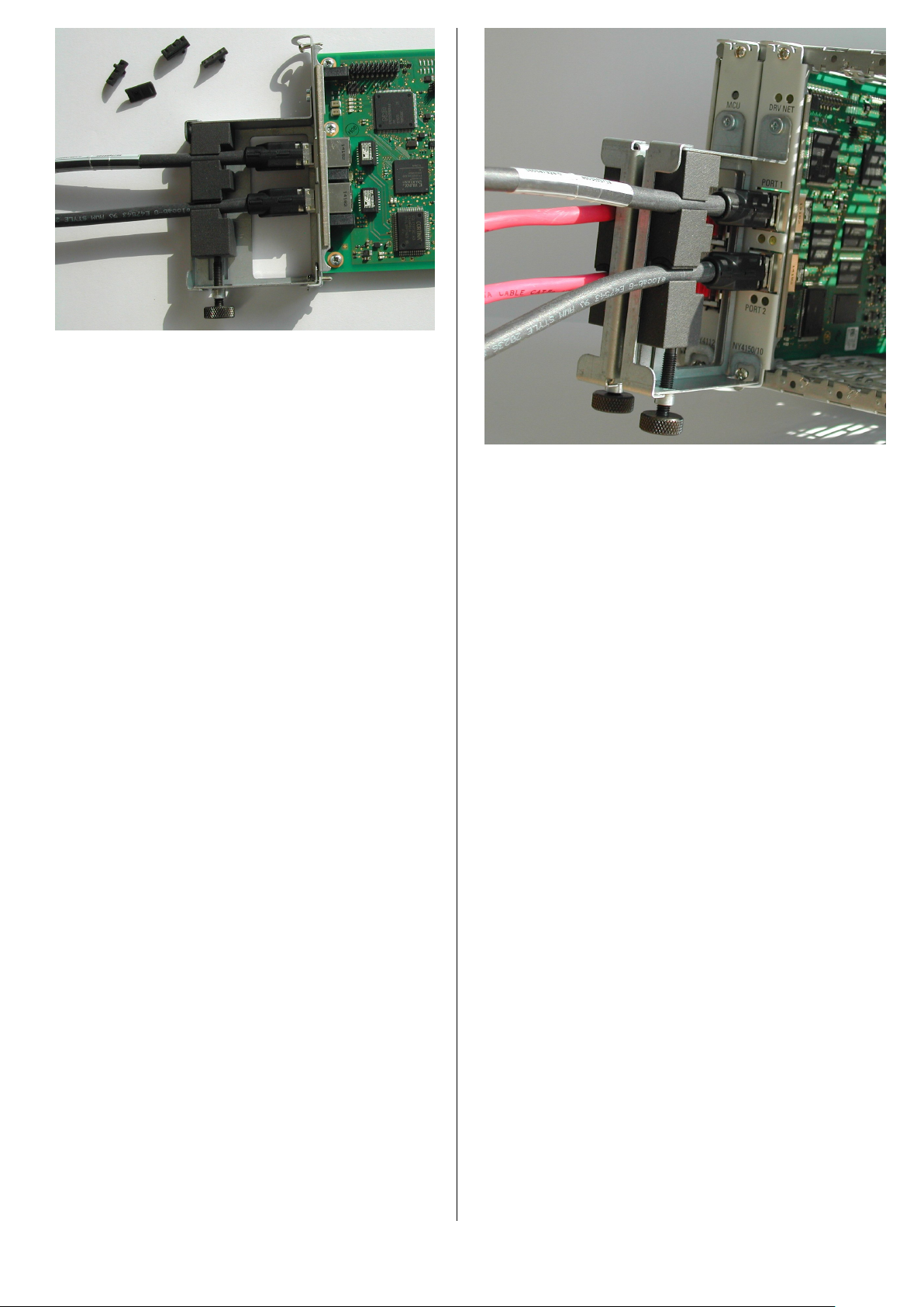
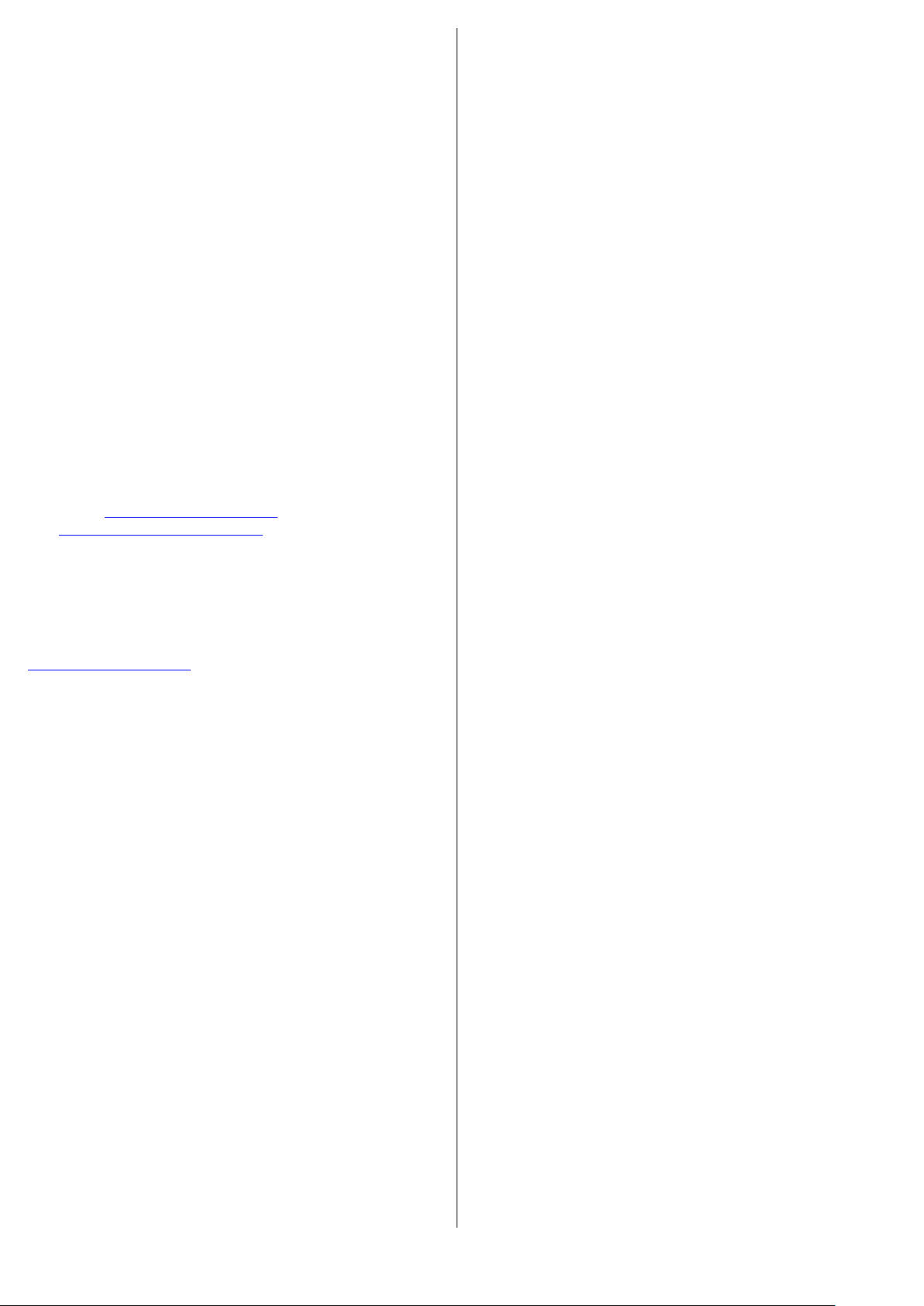
8 Installation and Removal
_________________________________________________________________
Damage to the NY4150/10 may occur
due to electrostatic discharges.
Comply with all ESD protective measures while working
with modules and components. Avoid electrostatic dis-
charges.
_________________________________________________________________
Power supplies must be switched off with the disconnect-
ing device installed in the cabinet.
8.1 Mechanical dimensions
The dimensions of the cable strain relief bracket are the
following.
You can see the dimensions of the cable strain relief
bracket in the following views.
Operating Storage and transport
Maximum environment
temperature
+5 ... +55 °C -40 °C … +85 °C
Relative Humidity
10 % … 90 %
(non-condensing)
5 % … 95 %
(non-condensing)
Mechanical Strength
Vibration:
IEC 60068-2-6:2007
Vibration, broadband:
IEC 60068-2-64:2008
Shock:
IEC 60068-2-27:2008
Pollution degree
2
2
Overvoltage category
II
Maximum altitude 4000 m
Type code
Width
Height
Depth
NYA04.1-STRAIN-RELIEF-4150-NY4901/40
18
mm
102.3
mm
65
mm
R911404771-01_BAL_DOC
December 7, 2020
Page 3 of 5
8.2 Installation of the cable strain relief bracket
Do the following steps to install the cable strain relief
bracket on the NY4150/10 module.
Precondition
The NY4150/10 module is installed in the NYCe4000
standard housing.
1. When you look at the front of the cable strain re-
lief bracket, the plate with the slits is at the left
side of the bracket. Hook the lower corner of the
bracket (the corner shown in Figure 1 at the bot-
tom left side) onto the bottom end of the front of
the NY4150/10 at an angle of approximately 60°.
2. Place the bracket against the front of the
NY4150/10 module, and install the bracket with
the mounting screw. Maximum torque is 0.7 Nm.
☞Make sure that your machine design has sufficient
free clearance space in front of the NY4150/10 module for
the cable strain relief bracket and maximum allowed
bending of the connection cables.
8.3 Installation of the connection cables
Loosen the lock screw at the bottom of the bracket to in-
stall the connection cables onto the cable strain relief
bracket.
Remark.
The figures show the NY4150/10 module outside the
standard housing for clarity. If the bracket is installed on
the NY4150/10 module before the module is installed in
the standard housing, it is not possible to tighten the
lower mounting screw of the NY4150/10 module.
Figure 2. NY4901/40 cable strain relief bracket on NY4150/10
Do the following steps to install the connection cables on
the cable strain relief bracket.
1. Slide the lower two clamping blocks completely to
the bottom side of the bracket. Slide the top clamping
block against the top side of the bracket.
2. Between the upper and lower clamping blocks and
the clamping block in the middle are 3 small parts.
See figure 2.
•If you use thick connection cables, you have to
remove these 3 parts.
•If you use thin connection cables, you only remove
the small part in the middle.
3. Connect the SERCOS cable to PORT 1 of the
NY4150/10 module. See Figure 3.
Figure 3. SERCOS cable connected to PORT 1
4. Slide the middle clamping block upward, so that the
SERCOS cable is held between the cable guidance of
the upper and middle clamping block.
5. Connect the second SERCOS cable to PORT 2 of the
NY4150/10 module. See Figure 4.
Figure 4. SERCOS cable connected to PORT 2
6. Slide the lower clamping block upward so that the
second SERCOS cable is held between the cable
guidance of the middle and lower clamping block.
7. Tighten the lock screw so that the clamping blocks
keep the SERCOS cables firmly in place. See figure 5.
Maximum tightening torque is 0.2 Nm.
R911404771-01_BAL_DOC
December 7, 2020
Page 4 of 5
Figure 5. SERCOS cables firmly in place
8.4 Disconnection of the SERCOS cables
Do the following steps to disconnect the SERCOS cables
from the NY4150/10 module.
1. Loosen the lock screw at the bottom of the bracket.
2. Slide the lower clamping block to the bottom of the
bracket.
3. Disconnect the SERCOS cable from PORT 2 of the
NY4150/10 module.
4. Slide the middle clamping block towards the bottom
of the bracket.
5. Disconnect the SERCOS cable from PORT 1 of the
NY4150/10 module.
8.5 Removal of the cable strain relief bracket
Do the following steps to remove the cable strain relief
bracket from the NY4150/10 module.
1. Disconnect the SERCOS cables from the NY4150/10
module. See chapter 8.4.
2. Loosen the mounting screw at the top side of the ca-
ble strain relief bracket.
3. Pivot the cable strain relief bracket to an angle of ap-
proximately 60° and lift the bracket from the
NY4150/10 module.
9 Description of the cable strain relief bracket
The cable strain relief bracket has a knurled screw on the
bottom at the front side. Looking at the front side, the
bracket has a metal plate at the left side with two slits in
it. Three clamping blocks slide in these slits. On the top
side of the bracket is the product identification label.
Figure 6 shows the NY4901/40 cable strain relief
bracket installed on the NY4150/10 module, next to the
cable strain relief bracket (NY4901/20) on the NY4112.
Figure 6. NY4901/40 bracket on NY4150/10 in system housing
10 Maintenance
The cable strain relief bracket has no special maintenance
requirements.
11 Disposal
11.1 Products
Our products can be returned to us free of charge for dis-
posal. It is a precondition, however, that the products are
free of oil, grease or other dirt. In addition, when returned
the products must not contain any undue foreign matter
or foreign component.
Please send the products “free domicile” to the following
address:
Bosch Rexroth AG
Bgm-Dr.-Nebel-Str. 2
97816 Lohr a.Main, Germany
11.2 Packaging materials
The packaging materials consist of cardboard, wood and
polystyrene. They can be easily recycled. For ecological
reasons you should not return the empty packages to us.
11.3 Environmental protection
•No release of hazardous substances.
Our products do not contain any hazardous substanc-
es that they can release in the case of appropriate
use. Normally there aren't any negative effects on the
environment to be expected.
•Materials contained in the products.
Electronic devices
Electronic devices mainly contain:
- steel
- aluminum
- copper
- synthetic materials
- electronic components and
modules
R911404771-01_BAL_DOC
December 7, 2020
Page 5 of 5
•Recycling.
Due to their high content of metal most of the prod-
uct components can be recycled. In order to recycle
the metal in the best possible way it is necessary to
disassemble the products into individual modules.
The metals contained in the electric and electronic
modules can also be recycled by means of specific
separation processes.
The synthetic materials remaining after these pro-
cesses can be thermally recycled.
12 Service and Addresses
12.1 Service
Our service department at our main facility
Bosch Rexroth Service
Bürgermeister-Dr.-Nebel Straße 2
97816 Lohr am Main
Deutschland
is always available for information and help.
You can reach us at:
•Telephone: +49 9352 40 50 60
•Hotline: +49 9352 40 50 60
•Email: service@boschrexroth.de
•www.boschrexroth.de/service
Please check the internet company addresses for hotline
call numbers in other countries.
12.2 Addresses
You can find the addresses of our companies on
www.boschrexroth.com.
On the website you can also find additional infor-
mation for service, repair (for example supplier address-
es) and training.
Please contact your nearest supplier or representative in
your country first before contacting Service Deutschland,
if you are outside Germany.
Notes

Other Bosch TV Mount manuals

Bosch UML-150-90 User manual

Bosch

Bosch UML-150-90 User manual

Bosch FLM-IFB126-S User manual

Bosch

Bosch FLM-IFB126-S User manual

Bosch FPO-5000-PSB-CH User manual

Bosch

Bosch FPO-5000-PSB-CH User manual

Popular TV Mount manuals by other brands

Init 08-1442 Assembly instructions

Init

Init 08-1442 Assembly instructions

Elived YD1007 installation instructions

Elived

Elived YD1007 installation instructions

KROMAX LEDAS-30 instructions

KROMAX

KROMAX LEDAS-30 instructions

Nordic DELTACO ARM-0301 user manual

Nordic

Nordic DELTACO ARM-0301 user manual

PEERLESS ECMU-01-C-S Installation and assembly

PEERLESS

PEERLESS ECMU-01-C-S Installation and assembly

Atdec AWM-A13H installation guide

Atdec

Atdec AWM-A13H installation guide

HUANUO HNDSK1 instructions

HUANUO

HUANUO HNDSK1 instructions

Gladiator Joe GJ0A0020 quick start guide

Gladiator Joe

Gladiator Joe GJ0A0020 quick start guide

Sanus VisionMount MD115 manual

Sanus VisionMount

Sanus VisionMount MD115 manual

Displays2go Universal LPGP36WB manual

Displays2go

Displays2go Universal LPGP36WB manual

Init NT-TVM204 Assembly instructions

Init

Init NT-TVM204 Assembly instructions

Granberg Basicline 406 operating instructions

Granberg

Granberg Basicline 406 operating instructions

GEM LZ-400N Specification sheet

GEM

GEM LZ-400N Specification sheet

Premier Mounts PWM-F110 installation manual

Premier Mounts

Premier Mounts PWM-F110 installation manual

Shakespeare Electronic 484 installation instructions

Shakespeare Electronic

Shakespeare Electronic 484 installation instructions

EAW UB82e installation instructions

EAW

EAW UB82e installation instructions

Pioneer PDK-WT02 operating instructions

Pioneer

Pioneer PDK-WT02 operating instructions

Rapid video mounts RVM-44FM70D instruction manual

Rapid video mounts

Rapid video mounts RVM-44FM70D instruction manual

manuals.online logo
manuals.online logoBrands
  • About & Mission
  • Contact us
  • Privacy Policy
  • Terms and Conditions

Copyright 2025 Manuals.Online. All Rights Reserved.