Bosch Rexroth IndraControl VAU 01.1U Technical manual

Project Planning Manual
Electric Drives
and Controls Pneumatics Service
Linear Motion and
Assembly Technologies
Hydraulics
Rexroth IndraControl
VAU 01.1U
UPS with USB interface
R911323872
Edition 03

Rexroth IndraControl
VAU 01.1U
UPS with USB interface
Project Planning Manual
DOK-SUPPL*-VAU*01.1U**-PR03-EN-P
RS-63f14a7a7429dc0f0a6846a00117a35b-3-en-US-3
This documentation describes the uninterruptible power supply VAU 01.1U
with USB interface.
Edition Release Date Notes
First edition 09.2008 -
Second edition 03.2009 Revised edition (EMC)
Third edition 09.2011 Revised edition
Copyright © Bosch Rexroth AG 2011
This document, as well as the data, specifications and other information set
forth in it, are the exclusive property of Bosch Rexroth AG. It may not be re‐
produced or given to third parties without its consent.
Liability The specified data is intended for product description purposes only and shall
not be deemed to be a guaranteed characteristic unless expressly stipulated
in the contract. All rights are reserved with respect to the content of this docu‐
mentation and the availability of the product.
Published by Bosch Rexroth AG
Bgm.-Dr.-Nebel-Str. 2 ■ 97816 Lohr am Main, Germany
Phone +49 (0)93 52/ 40-0 ■ Fax +49 (0)93 52/ 40-48 85
http://www.boschrexroth.com/
Development Control Platform GW (CS)
Note This document has been printed on chlorine-free bleached paper.
Title
Type of Documentation
Document Typecode
Internal File Reference
Purpose of Documentation
Record of Revision
Bosch Rexroth AG DOK-SUPPL*-VAU*01.1U**-PR03-EN-P
Rexroth IndraControl VAU 01.1U UPS with USB interface

Table of Contents
Page
1 System Presentation...................................................................................................... 5
1.1 Brief Description VAU 01.1U.................................................................................................................. 5
1.2 Permitted Devices................................................................................................................................... 6
1.3 Software.................................................................................................................................................. 6
1.4 Further Documentation........................................................................................................................... 6
1.5 Steps for Commissioning........................................................................................................................ 6
2 Important Instructions on Use ....................................................................................... 7
2.1 Intended Use ......................................................................................................................................... 7
2.1.1 Introduction.......................................................................................................................................... 7
2.1.2 Areas of Use and Application.............................................................................................................. 7
2.2 Unintended Use...................................................................................................................................... 8
3 Safety Instructions for Electric Drives and Controls....................................................... 9
3.1 Definitions of Terms................................................................................................................................ 9
3.2 General Information.............................................................................................................................. 10
3.2.1 Using the Safety Instructions and Passing Them on to Others......................................................... 10
3.2.2 Requirements for Safe Use............................................................................................................... 10
3.2.3 Hazards by Improper Use.................................................................................................................. 11
3.3 Instructions with Regard to Specific Dangers....................................................................................... 13
3.3.1 Protection Against Contact With Electrical Parts and Housings........................................................ 13
3.3.2 Protective Extra-Low Voltage as Protection Against Electric Shock ................................................ 14
3.3.3 Protection Against Dangerous Movements....................................................................................... 15
3.3.4 Protection Against Magnetic and Electromagnetic Fields During Operation and Mounting.............. 16
3.3.5 Protection Against Contact With Hot Parts........................................................................................ 16
3.3.6 Protection During Handling and Mounting......................................................................................... 17
3.3.7 Battery Safety.................................................................................................................................... 17
3.3.8 Protection Against Pressurized Systems........................................................................................... 18
3.4 Explanation of Signal Words and the Safety Alert Symbol................................................................... 18
4 Technical Data............................................................................................................. 21
4.1 Degree of Protection and Weight.......................................................................................................... 21
4.2 Input Voltage and Output Voltage......................................................................................................... 21
4.2.1 Input Voltage+24 V............................................................................................................................ 21
4.2.2 Output Voltage................................................................................................................................... 21
4.3 Ambient Conditions............................................................................................................................... 22
4.4 Standards............................................................................................................................................. 22
4.4.1 Used Standards................................................................................................................................. 22
4.4.2 CE Marking........................................................................................................................................ 23
Declaration of Conformity .............................................................................................................. 23
Note for the Machine Manufacturer................................................................................................ 23
4.4.3 UL and CSA certified......................................................................................................................... 24
4.5 Wear Parts............................................................................................................................................ 24
DOK-SUPPL*-VAU*01.1U**-PR03-EN-P
Rexroth IndraControl VAU 01.1U UPS with USB interface
Bosch Rexroth AG I/63
Table of Contents

Page
4.6 Compatibility Test................................................................................................................................. 24
5 Dimensions, Mounting and Dismounting..................................................................... 25
5.1 Task...................................................................................................................................................... 25
5.2 Housing Dimensions............................................................................................................................. 25
5.3 Mounting and Dismounting................................................................................................................... 25
5.3.1 Mounting Notes................................................................................................................................. 25
5.3.2 Mounting............................................................................................................................................ 26
5.3.3 Dismounting....................................................................................................................................... 27
6 Operating and Display Components............................................................................ 29
6.1 Task...................................................................................................................................................... 29
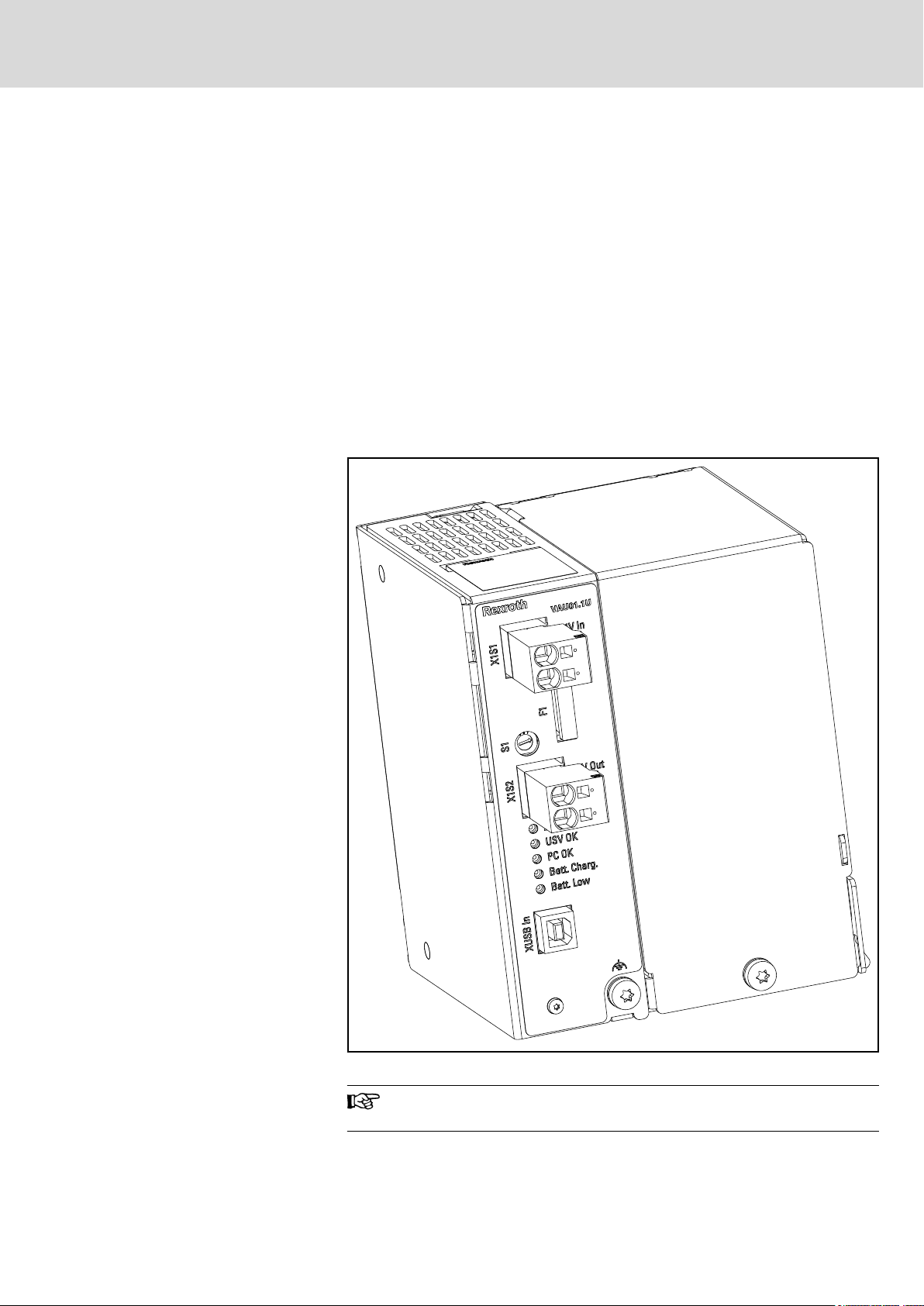
6.2 Connector Panel................................................................................................................................... 29
6.2.1 General Information........................................................................................................................... 29
6.2.2 Overview of the LEDs for Operating and Error Display..................................................................... 30
6.3 Fuse F1................................................................................................................................................. 31
6.4 Rotary Switch S1.................................................................................................................................. 32
6.4.1 Position of S1 Rotary Switch............................................................................................................. 32
6.4.2 General Information........................................................................................................................... 32
6.4.3 Timing Depending on the Position of S1 Rotary Switch.................................................................... 32
6.4.4 Timing Depending on the Position of Rotary Switch S1 and Settings in the UPS-NT Control Software
........................................................................................................................................................... 33
7 Interfaces and Wiring .................................................................................................. 39
7.1 Task...................................................................................................................................................... 39
7.2 Connector Panel................................................................................................................................... 39
7.2.1 General Information........................................................................................................................... 39
7.2.2 Overview of the Connections............................................................................................................. 40
7.3 Voltage Connection.............................................................................................................................. 41
7.3.1 General Information........................................................................................................................... 41
7.3.2 Wiring the Power Connection............................................................................................................ 41
7.3.3 Wiring of the VAU 01.1U, Cable Lengths and Cable Cross-Sections............................................... 44
7.4 Interface XUSB In................................................................................................................................. 44
7.4.1 General Information........................................................................................................................... 44
8 Maintenance, Storage and Transport.......................................................................... 47
8.1 Task...................................................................................................................................................... 47
8.2 General Information.............................................................................................................................. 47
8.3 Replacing Batteries............................................................................................................................... 48
8.4 Storing the VAU 01.1U......................................................................................................................... 51
8.5 Transporting the VAU 01.1U................................................................................................................. 51
9 Ordering Information.................................................................................................... 53
9.1 Type Designation Code........................................................................................................................ 53
Bosch Rexroth AG DOK-SUPPL*-VAU*01.1U**-PR03-EN-P
Rexroth IndraControl VAU 01.1U UPS with USB interface
II/63
Table of Contents

Page
9.2 Accessories.......................................................................................................................................... 54
9.3 Further Documentation......................................................................................................................... 54
10 Environmental Protection and Disposal ...................................................................... 55
10.1 Environmental Protection...................................................................................................................... 55
10.2 Disposal................................................................................................................................................ 55
11 Service and Support.................................................................................................... 57
Glossary VAU 01.1U.................................................................................................... 59
Index............................................................................................................................ 61
DOK-SUPPL*-VAU*01.1U**-PR03-EN-P
Rexroth IndraControl VAU 01.1U UPS with USB interface
Bosch Rexroth AG III/63
Table of Contents

Bosch Rexroth AG DOK-SUPPL*-VAU*01.1U**-PR03-EN-P
Rexroth IndraControl VAU 01.1U UPS with USB interface
IV/63

1 System Presentation
1.1 Brief Description VAU 01.1U
The VAU 01.1U is a UPS (Uninterruptible Power Supply), which provides
power to the connected device for a limited time if the supply voltage fails
(DC 24 V).
The VAU 01.1U is able to provide the connected device with 24 V and 10 A
for max. three minutes. The communication between VAU 01.1U and con‐
nected device is realized via a USB interface (XUSB In). The VAU 01.1U
consists of the following components:
● Enclosed metal housing.
● A battery integrated in the device.
● Display and operating components on the front panel.
● Integrated burst and surge protection for the connected device.
Fig.1-1: View, VAU 01.1U with USB interface
This documentation describes only the uninterruptible power sup‐
ply (UPS) VAU01.1U-024-024-240-NN.
DOK-SUPPL*-VAU*01.1U**-PR03-EN-P
Rexroth IndraControl VAU 01.1U UPS with USB interface
Bosch Rexroth AG 5/63
System Presentation

1.2 Permitted Devices
The following permitted devices can be connected to the VAU 01.1U:
● Control cabinet PC Rexroth IndraControl VPB 40.3
● Panel PC Rexroth IndraControl VPP 16.3/40.3/60.3
● Control cabinet PC Rexroth IndraControl VSB 40.3
● Panel PC Rexroth IndraControl VSP 16.3/40.3/60.3
1.3 Software
The communication between VAU 01.1U and connected control cabinet PC
is realized via the USB interface (XUSB In). Therefore, the UPS software has
to be installed on the connected device. The installation is described in the
relevant documentation of the control cabinet PC or of the panel PC, see also
chapter 1.4 "Further Documentation" on page 6.
1.4 Further Documentation
Documentation Order code of the documenta‐
tion
Parts number
Rexroth IndraControl
VPB 40.3
DOK-SUPPL*-VPB*40.3***-
PRxx-EN-P
R911323876
Rexroth IndraControl
VPP 16.3/40.3/60.3
DOK-SUPPL*-VPP*XX.3***-
PRxx-EN-P
R911323511
Rexroth IndraControl
VSB 40.3
DOK-SUPPL*-VSB*40.3***-
PRxx-EN-P
R911323880
Rexroth IndraControl
VSP 16.3/40.3
DOK-SUPPL*-VSP*XX.3***-
PRxx-EN-P
R911323882
Fig.1-2: Further documentation for devices which are permitted for the VAU
01.1U
1.5 Steps for Commissioning
Befor using the UPS, ensure that
● the device to be connected is permitted for the VAU 01.1U,
● the required software (UPS NT Control) is installed,
● the switch positions are correct,
● the correct order for mounting, connection and cabling is kept.
Bosch Rexroth AG DOK-SUPPL*-VAU*01.1U**-PR03-EN-P
Rexroth IndraControl VAU 01.1U UPS with USB interface
6/63
System Presentation

2 Important Instructions on Use
2.1 Intended Use
2.1.1 Introduction
The Rexroth products represent state-of-the-art developments and manufac‐
turing. They are tested prior to delivery to ensure operating safety and relia‐
bility.
If the products are not used as intended, sit‐
uations occur that can result in damage to
property and injury to persons.
WARNING
The products are designed for the use in an industrial environment and may
therefore only be used for the intended purpose. If they are not used as in‐
tended, situations causing personal injury as well as material damage can oc‐
cur.
Rexroth is not liable for damages resulting from unintended use.
In such cases, the guarantee and the right to payment of dam‐
ages resulting from unintended use are forfeited. The user alone
carries all responsibility of the risks.
Before using Bosch Rexroth products, the following requirements must be
met to ensure intended use of the products:
● Personnel who in any way, shape, form or use one of our products must
first read and understand the relevant safety instructions and be familiar
with the intended use of the products.
● If the product takes the form of hardware, then they must remain in the
original state; in other words, no structural changes are permitted. The
decompilation of software products or the alteration of source codes is
not permitted.
● Do not install or operate damaged or faulty products.
● Ensure that the products have been installed in the manner described in
the relevant documentation.
2.1.2 Areas of Use and Application
Danger of destruction of the device if not ex‐
pressly stated accessories, mounting parts
and other components, cables, lines, soft‐
ware and firmware is used.
NOTICE
The VAU 01.1U may only be used with the accessories and mounting parts
listed in this documentation. Components that are not expressly mentioned
must neither be attached nor connected. The same is valid for cables and
lines.
Operation must only be carried out with the hardware component configura‐
tions and combinations that are expressly specified and with the software and
firmware indicated and specified in the respective documentation and func‐
tional descriptions.
DOK-SUPPL*-VAU*01.1U**-PR03-EN-P
Rexroth IndraControl VAU 01.1U UPS with USB interface
Bosch Rexroth AG 7/63
Important Instructions on Use

The UPS may only be operated under the mounting and installation condi‐
tions, the position, and the ambient conditions (temperature, degree of pro‐
tection, humidity, EMC etc.) specified in the related documentation.
2.2 Unintended Use
The use of the UPS in applications other than those specified or described in
the documentation and the technical specifications is considered as "uninten‐
ded".
The UPS must not be used if
● it is exposed to operation conditions which do not correspond to the
specified ambient conditions. Operation under water, extreme tempera‐
ture fluctuations or extreme maximum temperatures is prohibited.
● the intended applications have not expressly been allowed by Bosch
Rexroth. Please read the information given in the general safety instruc‐
tions!
Bosch Rexroth AG DOK-SUPPL*-VAU*01.1U**-PR03-EN-P
Rexroth IndraControl VAU 01.1U UPS with USB interface
8/63
Important Instructions on Use

3 Safety Instructions for Electric Drives and Controls
3.1 Definitions of Terms
Application Documentation Application documentation comprises the entire documentation used to in‐
form the user of the product about the use and safety-relevant features for
configuring, integrating, installing, mounting, commissioning, operating, main‐
taining, repairing and decommissioning the product. The following terms are
also used for this kind of documentation: User Guide, Operation Manual,
Commissioning Manual, Instruction Manual, Project Planning Manual, Appli‐
cation Manual, etc.
Component A component is a combination of elements with a specified function, which
are part of a piece of equipment, device or system. Components of the elec‐
tric drive and control system are, for example, supply units, drive controllers,
mains choke, mains filter, motors, cables, etc.
Control System A control system comprises several interconnected control components
placed on the market as a single functional unit.
Device A device is a finished product with a defined function, intended for users and
placed on the market as an individual piece of merchandise.
Electrical Equipment Electrical equipment encompasses all devices used to generate, convert,
transmit, distribute or apply electrical energy, such as electric motors, trans‐
formers, switching devices, cables, lines, power-consuming devices, circuit
board assemblies, plug-in units, control cabinets, etc.
Electric Drive System An electric drive system comprises all components from mains supply to mo‐
tor shaft; this includes, for example, electric motor(s), motor encoder(s), sup‐
ply units and drive controllers, as well as auxiliary and additional compo‐
nents, such as mains filter, mains choke and the corresponding lines and ca‐
bles.
Installation An installation consists of several devices or systems interconnected for a
defined purpose and on a defined site which, however, are not intended to be
placed on the market as a single functional unit.
Machine A machine is the entirety of interconnected parts or units at least one of
which is movable. Thus, a machine consists of the appropriate machine drive
elements, as well as control and power circuits, which have been assembled
for a specific application. A machine is, for example, intended for processing,
treatment, movement or packaging of a material. The term "machine" also
covers a combination of machines which are arranged and controlled in such
a way that they function as a unified whole.
Manufacturer The manufacturer is an individual or legal entity bearing responsibility for the
design and manufacture of a product which is placed on the market in the in‐
dividual's or legal entity's name. The manufacturer can use finished products,
finished parts or finished elements, or contract out work to subcontractors.
However, the manufacturer must always have overall control and possess
the required authority to take responsibility for the product.
Product Examples of a product: Device, component, part, system, software, firmware,
among other things.
Project Planning Manual A project planning manual is part of the application documentation used to
support the sizing and planning of systems, machines or installations.
Qualified Persons In terms of this application documentation, qualified persons are those per‐
sons who are familiar with the installation, mounting, commissioning and op‐
eration of the components of the electric drive and control system, as well as
with the hazards this implies, and who possess the qualifications their work
DOK-SUPPL*-VAU*01.1U**-PR03-EN-P
Rexroth IndraControl VAU 01.1U UPS with USB interface
Bosch Rexroth AG 9/63
Safety Instructions for Electric Drives and Controls

requires. To comply with these qualifications, it is necessary, among other
things,
1) to be trained, instructed or authorized to switch electric circuits and devi‐
ces safely on and off, to ground them and to mark them
2) to be trained or instructed to maintain and use adequate safety equipment
3) to attend a course of instruction in first aid
User A user is a person installing, commissioning or using a product which has
been placed on the market.
3.2 General Information
3.2.1 Using the Safety Instructions and Passing Them on to Others
Do not attempt to install and operate the components of the electric drive and
control system without first reading all documentation provided with the prod‐
uct. Read and understand these safety instructions and all user documenta‐
tion prior to working with these components. If you do not have the user doc‐
umentation for the components, contact your responsible Bosch Rexroth
sales partner. Ask for these documents to be sent immediately to the person
or persons responsible for the safe operation of the components.
If the component is resold, rented and/or passed on to others in any other
form, these safety instructions must be delivered with the component in the
official language of the user's country.
Improper use of these components, failure to follow the safety instructions in
this document or tampering with the product, including disabling of safety de‐
vices, could result in property damage, injury, electric shock or even death.
3.2.2 Requirements for Safe Use
Read the following instructions before initial commissioning of the compo‐
nents of the electric drive and control system in order to eliminate the risk of
injury and/or property damage. You must follow these safety instructions.
● Bosch Rexroth is not liable for damages resulting from failure to observe
the safety instructions.
● Read the operating, maintenance and safety instructions in your lan‐
guage before commissioning. If you find that you cannot completely un‐
derstand the application documentation in the available language,
please ask your supplier to clarify.
● Proper and correct transport, storage, mounting and installation, as well
as care in operation and maintenance, are prerequisites for optimal and
safe operation of the component.
● Only qualified persons may work with components of the electric drive
and control system or within its proximity.
● Only use accessories and spare parts approved by Bosch Rexroth.
● Follow the safety regulations and requirements of the country in which
the components of the electric drive and control system are operated.
● Only use the components of the electric drive and control system in the
manner that is defined as appropriate. See chapter "Appropriate Use".
● The ambient and operating conditions given in the available application
documentation must be observed.
● Applications for functional safety are only allowed if clearly and explicitly
specified in the application documentation "Integrated Safety Technolo‐
Bosch Rexroth AG DOK-SUPPL*-VAU*01.1U**-PR03-EN-P
Rexroth IndraControl VAU 01.1U UPS with USB interface
10/63
Safety Instructions for Electric Drives and Controls

gy". If this is not the case, they are excluded. Functional safety is a safe‐
ty concept in which measures of risk reduction for personal safety de‐
pend on electrical, electronic or programmable control systems.
● The information given in the application documentation with regard to
the use of the delivered components contains only examples of applica‐
tions and suggestions.
The machine and installation manufacturers must
– make sure that the delivered components are suited for their indi‐
vidual application and check the information given in this applica‐
tion documentation with regard to the use of the components,
– make sure that their individual application complies with the appli‐
cable safety regulations and standards and carry out the required
measures, modifications and complements.
● Commissioning of the delivered components is only allowed once it is
sure that the machine or installation in which the components are instal‐
led complies with the national regulations, safety specifications and
standards of the application.
● Operation is only allowed if the national EMC regulations for the applica‐
tion are met.
● The instructions for installation in accordance with EMC requirements
can be found in the section on EMC in the respective application docu‐
mentation.
The machine or installation manufacturer is responsible for compliance
with the limit values as prescribed in the national regulations.
● The technical data, connection and installation conditions of the compo‐
nents are specified in the respective application documentations and
must be followed at all times.
National regulations which the user must take into account
● European countries: In accordance with European EN standards
● United States of America (USA):
– National Electrical Code (NEC)
– National Electrical Manufacturers Association (NEMA), as well as
local engineering regulations
– Regulations of the National Fire Protection Association (NFPA)
● Canada: Canadian Standards Association (CSA)
● Other countries:
– International Organization for Standardization (ISO)
– International Electrotechnical Commission (IEC)
3.2.3 Hazards by Improper Use
● High electrical voltage and high working current! Danger to life or seri‐
ous injury by electric shock!
● High electrical voltage by incorrect connection! Danger to life or injury by
electric shock!
● Dangerous movements! Danger to life, serious injury or property dam‐
age by unintended motor movements!
● Health hazard for persons with heart pacemakers, metal implants and
hearing aids in proximity to electric drive systems!
DOK-SUPPL*-VAU*01.1U**-PR03-EN-P
Rexroth IndraControl VAU 01.1U UPS with USB interface
Bosch Rexroth AG 11/63
Safety Instructions for Electric Drives and Controls

● Risk of burns by hot housing surfaces!
● Risk of injury by improper handling! Injury by crushing, shearing, cutting,
hitting!
● Risk of injury by improper handling of batteries!
● Risk of injury by improper handling of pressurized lines!
Bosch Rexroth AG DOK-SUPPL*-VAU*01.1U**-PR03-EN-P
Rexroth IndraControl VAU 01.1U UPS with USB interface
12/63
Safety Instructions for Electric Drives and Controls

3.3 Instructions with Regard to Specific Dangers
3.3.1 Protection Against Contact With Electrical Parts and Housings
This section concerns components of the electric drive and con‐
trol system with voltages of more than 50 volts.
Contact with parts conducting voltages above 50 volts can cause personal
danger and electric shock. When operating components of the electric drive
and control system, it is unavoidable that some parts of these components
conduct dangerous voltage.
High electrical voltage! Danger to life, risk of injury by electric shock or seri‐
ous injury!
● Only qualified persons are allowed to operate, maintain and/or repair the
components of the electric drive and control system.
● Follow the general installation and safety regulations when working on
power installations.
● Before switching on, the equipment grounding conductor must have
been permanently connected to all electric components in accordance
with the connection diagram.
● Even for brief measurements or tests, operation is only allowed if the
equipment grounding conductor has been permanently connected to the
points of the components provided for this purpose.
● Before accessing electrical parts with voltage potentials higher than
50 V, you must disconnect electric components from the mains or from
the power supply unit. Secure the electric component from reconnec‐
tion.
● With electric components, observe the following aspects:
Always wait 30 minutes after switching off power to allow live capacitors
to discharge before accessing an electric component. Measure the elec‐
trical voltage of live parts before beginning to work to make sure that the
equipment is safe to touch.
● Install the covers and guards provided for this purpose before switching
on.
● Never touch electrical connection points of the components while power
is turned on.
● Do not remove or plug in connectors when the component has been
powered.
● Under specific conditions, electric drive systems can be operated at
mains protected by residual-current-operated circuit-breakers sensitive
to universal current (RCDs/RCMs).
● Secure built-in devices from penetrating foreign objects and water, as
well as from direct contact, by providing an external housing, for exam‐
ple a control cabinet.
High housing voltage and high leakage current! Danger to life, risk of injury
by electric shock!
● Before switching on and before commissioning, ground or connect the
components of the electric drive and control system to the equipment
grounding conductor at the grounding points.
DOK-SUPPL*-VAU*01.1U**-PR03-EN-P
Rexroth IndraControl VAU 01.1U UPS with USB interface
Bosch Rexroth AG 13/63
Safety Instructions for Electric Drives and Controls

● Connect the equipment grounding conductor of the components of the
electric drive and control system permanently to the main power supply
at all times. The leakage current is greater than 3.5 mA.
● Establish an equipment grounding connection with a minimum cross
section according to the table below. With an outer conductor cross sec‐
tion smaller than 10 mm2 (8 AWG), the alternative connection of two
equipment grounding conductors is allowed, each having the same
cross section as the outer conductors.
Cross section outer con‐
ductor
Minimum cross section equipment grounding conductor
Leakage current ≥ 3.5 mA
1 equipment grounding
conductor
2 equipment grounding
conductors
1,5 mm2 (AWG 16)
10 mm2 (AWG 8)
2 × 1,5 mm2 (AWG 16)
2,5 mm2 (AWG 14) 2 × 2,5 mm2 (AWG 14)
4 mm2 (AWG 12) 2 × 4 mm2 (AWG 12)
6 mm2 (AWG 10) 2 × 6 mm2 (AWG 10)
10 mm2 (AWG 8) -
16 mm2 (AWG 6)
16 mm2 (AWG 6)
-
25 mm2 (AWG 4) -
35 mm2 (AWG 2) -
50 mm2 (AWG 1/0) 25 mm2 (AWG 4) -
70 mm2 (AWG 2/0) 35 mm2 (AWG 2) -
... ... ...
Fig.3-1: Minimum Cross Section of the Equipment Grounding Connection
3.3.2 Protective Extra-Low Voltage as Protection Against Electric Shock
Protective extra-low voltage is used to allow connecting devices with basic in‐
sulation to extra-low voltage circuits.
On components of an electric drive and control system provided by Bosch
Rexroth, all connections and terminals with voltages between 5 and 50 volts
are PELV ("Protective Extra-Low Voltage") systems. It is allowed to connect
devices equipped with basic insulation (such as programming devices, PCs,
notebooks, display units) to these connections.
Danger to life, risk of injury by electric shock! High electrical voltage by incor‐
rect connection!
If extra-low voltage circuits of devices containing voltages and circuits of
more than 50 volts (e.g., the mains connection) are connected to Bosch
Rexroth products, the connected extra-low voltage circuits must comply with
the requirements for PELV ("Protective Extra-Low Voltage").
Bosch Rexroth AG DOK-SUPPL*-VAU*01.1U**-PR03-EN-P
Rexroth IndraControl VAU 01.1U UPS with USB interface
14/63
Safety Instructions for Electric Drives and Controls

3.3.3 Protection Against Dangerous Movements
Dangerous movements can be caused by faulty control of connected motors.
Some common examples are:
● Improper or wrong wiring or cable connection
● Operator errors
● Wrong input of parameters before commissioning
● Malfunction of sensors and encoders
● Defective components
● Software or firmware errors
These errors can occur immediately after equipment is switched on or even
after an unspecified time of trouble-free operation.
The monitoring functions in the components of the electric drive and control
system will normally be sufficient to avoid malfunction in the connected
drives. Regarding personal safety, especially the danger of injury and/or
property damage, this alone cannot be relied upon to ensure complete safety.
Until the integrated monitoring functions become effective, it must be as‐
sumed in any case that faulty drive movements will occur. The extent of faulty
drive movements depends upon the type of control and the state of opera‐
tion.
Dangerous movements! Danger to life, risk of injury, serious injury or property
damage!
A risk assessment must be prepared for the installation or machine, with its
specific conditions, in which the components of the electric drive and control
system are installed.
As a result of the risk assessment, the user must provide for monitoring func‐
tions and higher-level measures on the installation side for personal safety.
The safety regulations applicable to the installation or machine must be taken
into consideration. Unintended machine movements or other malfunctions
are possible if safety devices are disabled, bypassed or not activated.
To avoid accidents, injury and/or property damage:
● Keep free and clear of the machine’s range of motion and moving ma‐
chine parts. Prevent personnel from accidentally entering the machine’s
range of motion by using, for example:
– Safety fences
– Safety guards
– Protective coverings
– Light barriers
● Make sure the safety fences and protective coverings are strong enough
to resist maximum possible kinetic energy.
● Mount emergency stopping switches in the immediate reach of the oper‐
ator. Before commissioning, verify that the emergency stopping equip‐
ment works. Do not operate the machine if the emergency stopping
switch is not working.
● Prevent unintended start-up. Isolate the drive power connection by
means of OFF switches/OFF buttons or use a safe starting lockout.
● Make sure that the drives are brought to safe standstill before accessing
or entering the danger zone.
DOK-SUPPL*-VAU*01.1U**-PR03-EN-P
Rexroth IndraControl VAU 01.1U UPS with USB interface
Bosch Rexroth AG 15/63
Safety Instructions for Electric Drives and Controls

● Additionally secure vertical axes against falling or dropping after switch‐
ing off the motor power by, for example,
– mechanically securing the vertical axes,
– adding an external braking/arrester/clamping mechanism or
– ensuring sufficient counterbalancing of the vertical axes.
● The standard equipment motor holding brake or an external holding
brake controlled by the drive controller is not sufficient to guarantee per‐
sonal safety!
● Disconnect electrical power to the components of the electric drive and
control system using the master switch and secure them from reconnec‐
tion ("lock out") for:
– Maintenance and repair work
– Cleaning of equipment
– Long periods of discontinued equipment use
● Prevent the operation of high-frequency, remote control and radio equip‐
ment near components of the electric drive and control system and their
supply leads. If the use of these devices cannot be avoided, check the
machine or installation, at initial commissioning of the electric drive and
control system, for possible malfunctions when operating such high-fre‐
quency, remote control and radio equipment in its possible positions of
normal use. It might possibly be necessary to perform a special electro‐
magnetic compatibility (EMC) test.
3.3.4 Protection Against Magnetic and Electromagnetic Fields During Oper‐
ation and Mounting
Magnetic and electromagnetic fields generated by current-carrying conduc‐
tors or permanent magnets of electric motors represent a serious danger to
persons with heart pacemakers, metal implants and hearing aids.
Health hazard for persons with heart pacemakers, metal implants and hear‐
ing aids in proximity to electric components!
● Persons with heart pacemakers and metal implants are not allowed to
enter the following areas:
– Areas in which components of the electric drive and control sys‐
tems are mounted, commissioned and operated.
– Areas in which parts of motors with permanent magnets are stored,
repaired or mounted.
● If it is necessary for somebody with a heart pacemaker to enter such an
area, a doctor must be consulted prior to doing so. The noise immunity
of implanted heart pacemakers differs so greatly that no general rules
can be given.
● Those with metal implants or metal pieces, as well as with hearing aids,
must consult a doctor before they enter the areas described above.
3.3.5 Protection Against Contact With Hot Parts
Hot surfaces of components of the electric drive and control system. Risk of
burns!
Bosch Rexroth AG DOK-SUPPL*-VAU*01.1U**-PR03-EN-P
Rexroth IndraControl VAU 01.1U UPS with USB interface
16/63
Safety Instructions for Electric Drives and Controls

● Do not touch hot surfaces of, for example, braking resistors, heat sinks,
supply units and drive controllers, motors, windings and laminated
cores!
● According to the operating conditions, temperatures of the surfaces can
be higher than 60 °C (140 °F) during or after operation.
● Before touching motors after having switched them off, let them cool
down for a sufficient period of time. Cooling down can require up to 140
minutes! The time required for cooling down is approximately five times
the thermal time constant specified in the technical data.
● After switching chokes, supply units and drive controllers off, wait 15 mi‐
nutes to allow them to cool down before touching them.
● Wear safety gloves or do not work at hot surfaces.
● For certain applications, and in accordance with the respective safety
regulations, the manufacturer of the machine or installation must take
measures to avoid injuries caused by burns in the final application.
These measures can be, for example: Warnings at the machine or in‐
stallation, guards (shieldings or barriers) or safety instructions in the ap‐
plication documentation.
3.3.6 Protection During Handling and Mounting
Risk of injury by improper handling! Injury by crushing, shearing, cutting, hit‐
ting!
● Observe the relevant statutory regulations of accident prevention.
● Use suitable equipment for mounting and transport.
● Avoid jamming and crushing by appropriate measures.
● Always use suitable tools. Use special tools if specified.
● Use lifting equipment and tools in the correct manner.
● Use suitable protective equipment (hard hat, safety goggles, safety
shoes, safety gloves, for example).
● Do not stand under hanging loads.
● Immediately clean up any spilled liquids from the floor due to the risk of
falling!
3.3.7 Battery Safety
Batteries consist of active chemicals in a solid housing. Therefore, improper
handling can cause injury or property damage.
Risk of injury by improper handling!
● Do not attempt to reactivate low batteries by heating or other methods
(risk of explosion and cauterization).
● Do not attempt to recharge the batteries as this may cause leakage or
explosion.
● Do not throw batteries into open flames.
● Do not dismantle batteries.
● When replacing the battery/batteries, do not damage the electrical parts
installed in the devices.
● Only use the battery types specified for the product.
DOK-SUPPL*-VAU*01.1U**-PR03-EN-P
Rexroth IndraControl VAU 01.1U UPS with USB interface
Bosch Rexroth AG 17/63
Safety Instructions for Electric Drives and Controls

Environmental protection and disposal! The batteries contained in
the product are considered dangerous goods during land, air, and
sea transport (risk of explosion) in the sense of the legal regula‐
tions. Dispose of used batteries separately from other waste. Ob‐
serve the national regulations of your country.
3.3.8 Protection Against Pressurized Systems
According to the information given in the Project Planning Manuals, motors
and components cooled with liquids and compressed air can be partially sup‐
plied with externally fed, pressurized media, such as compressed air, hy‐
draulics oil, cooling liquids and cooling lubricants. Improper handling of the
connected supply systems, supply lines or connections can cause injuries or
property damage.
Risk of injury by improper handling of pressurized lines!
● Do not attempt to disconnect, open or cut pressurized lines (risk of ex‐
plosion).
● Observe the respective manufacturer's operating instructions.
● Before dismounting lines, relieve pressure and empty medium.
● Use suitable protective equipment (safety goggles, safety shoes, safety
gloves, for example).
● Immediately clean up any spilled liquids from the floor due to the risk of
falling!
Environmental protection and disposal! The agents (e.g., fluids)
used to operate the product might not be environmentally friendly.
Dispose of agents harmful to the environment separately from
other waste. Observe the national regulations of your country.
3.4 Explanation of Signal Words and the Safety Alert Symbol
The Safety Instructions in the available application documentation contain
specific signal words (DANGER, WARNING, CAUTION or NOTICE) and,
where required, a safety alert symbol (in accordance with
ANSI Z535.6-2006).
The signal word is meant to draw the reader's attention to the safety instruc‐
tion and identifies the hazard severity.
The safety alert symbol (a triangle with an exclamation point), which pre‐
cedes the signal words DANGER, WARNING and CAUTION, is used to alert
the reader to personal injury hazards.
DANGER
In case of non-compliance with this safety instruction, death or serious injury
will occur.
Bosch Rexroth AG DOK-SUPPL*-VAU*01.1U**-PR03-EN-P
Rexroth IndraControl VAU 01.1U UPS with USB interface
18/63
Safety Instructions for Electric Drives and Controls
Table of contents
Other Bosch UPS manuals