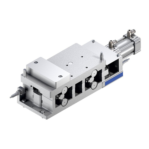
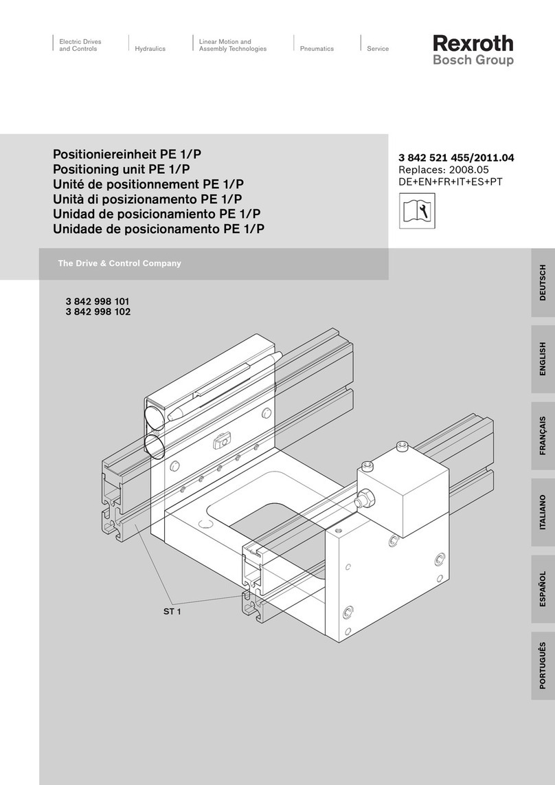
Bosch rexroth PE 2/X User manual

Assembly instructions
3 842 564 350/2020-06
Replaces: –
ENGLISH
PE 2/X, PE 2/H, PE 4
Positioning unit
3 842 998 324
3 842 999 000
3 842 998 067
ENGLISH

2/40
Bosch Rexroth AG, MIT: PE 2/X, PE 2/H, PE 4, 3 842 564 350/2020-06
The information in this manual is for product description purposes only. Any information on how to use the product is only an example
and a recommendation. Catalog information is not binding. The information given does not release the user from the obligation of own
judgment and verification. Our products are subject to natural wear and aging.
© All rights reserved by Bosch Rexroth AG, including for the registration of industrial property rights. This document may not be
reproduced or distributed to third parties without our consent.
The cover depicts a sample configuration. The actual product may vary.
The original assembly instructions are in German.
DE Die vorliegende Montageanleitung ist in den hier angebenen Sprachen verfügbar. Weitere Sprachen auf Anfrage.
Als gedruckte Version oder als PDF-Datei zum Download aus dem Medienverzeichnis:
www.boschrexroth.com/medienverzeichnis
Geben Sie in die Suchmaske (oben rechts, unter „Suche“) 3 842 564 349 ein, dann klicken Sie auf „Suche“.
EN These assembly instructions are available in the languages indicated here. Other languages on request.
They come in a hard copy or a PDF file that can be downloaded from the media directory:
www.boschrexroth.com/mediadirectory
In the search mask (at the top right under “Search”) enter 3 842 564 350, then click on “Search”.
FR Les présentes instructions de montage sont disponibles dans les langues suivantes. Autres langues sur demande.
Disponible au téléchargement en version imprimée ou en fichier PDF à partir du répertoire médias :
www.boschrexroth.com/mediadirectory
Saisissez dans le champ de recherche (en haut à droite, sous « Search ») 3 842 564 351 puis cliquez sur « Search ».
IT Le presenti istruzioni di montaggio sono disponibili nelle lingue indicate qui. Altre lingue su richiesta.
Possono essere scaricate come versione stampata o file PDF dalla Media Directory:
Inserire www.boschrexroth.com/mediadirectory
nella maschera di ricerca (in alto a destra, sotto “Search”) 3 842 564 352 e poi fare clic su “Search”.
ES Las presentes instrucciones de montaje están disponibles en los idiomas indicados. Otros idiomas a petición.
Las instrucciones están disponibles como versión impresa o como archivo PDF para descargar del archivo de medios:
www.boschrexroth.com/mediadirectory
En el buscador (en la parte superior derecha, en “Search”) introduzca 3 842 564 353, a continuación haga clic en “Search”.
PT O presente manual de montagem está disponível nos idiomas aqui indicados. Demais idiomas, sob consulta.
Como versão impressa ou o arquivo PDF para download no diretório de mídias:
www.boschrexroth.com/mediadirectory
Insira a máscara de pesquisa (parte superior direita, em “Search”) 3 842 564 354, e clique em “Search”.
ZH 本安装说明书有这里给出的语言版本。还可按照需求提供其他语言版本。
有印刷版本或电子版本 PDF 文件供使用,电子版文件可在下列的公司网站媒体网页上下载:
www.boschrexroth.com/mediadirectory
在搜索窗口(右上角,“Search”之下)中输入 3 842 564 355,然后点击“Search”。
CS Tento montážní návod je k dispozici v uvedených jazycích. Další jazykové verze na vyžádání.
Jako tištěná verze nebo jako soubor ve formátu PDF ke stažení z adresáře médií:
www.boschrexroth.com/mediadirectory
Zadejte do vyhledávacího políčka (vpravo nahoře, pod „Search“) MTCS 564 349, poté klikněte na „Search“.
PL Niniejsza instrukcja montażu dostępna jest w podanych tutaj wersjach językowych. Inne wersje językowe na zapytanie.
W wersji drukowanej lub jako plik PDF do pobrania w wykazie mediów:
www.boschrexroth.com/mediadirectory
W polu wyszukiwania (na górze z prawej strony, w polu „Search”) MTPL 564 349, a następnie kliknąć „Search”.
HU A jelen szerelési utasítás az itt megadott nyelveken áll rendelkezésre. További nyelvek rendelésre.
Nyomtatott változatként vagy a médiakönyvtárból letölthető PDF-fájlként:
www.boschrexroth.com/mediadirectory
Írja be a keresőmezőbe (jobbra fent, a „Search” alatt): MTHU 564 349, majd kattintson a „Search” gombra.
RO Aceste instrucţiuni de montaj sunt disponibile în limbile enumerate aici. Alte limbi la cerere.
Sub formă de versiune tipărită sau ca fişier PDF pentru a fi descărcat din directorul de conţinuturi (mediadirectory):
www.boschrexroth.com/mediadirectory
Introduceţi în masca de căutare (sus, în partea dreaptă, la „Search“) MTRO 564 349, apoi faceţi clic pe „Search“.
DE 3 842 564 349 PE 2/X, PE 2/H, PE 4 Positioniereinheit Deutsch
EN 3 842 564 350 PE 2/X, PE 2/H, PE 4 Positioning unit English
FR 3 842 564 351 PE 2/X, PE 2/H, PE 4 Unité de positionnement Français
IT 3 842 564 352 PE 2/X, PE 2/H, PE 4 Unità di posizionamento Italiano
ES 3 842 564 353 PE 2/X, PE 2/H, PE 4 Unidad de posicionamiento Español
PT 3 842 564 354 PE 2/X, PE 2/H, PE 4 Unidade de posicionamento Português
ZH 3 842 564 355 PE 2/X, PE 2/H, PE 4 定位单元 中文
CS MTCS 564 349 1)PE 2/X, PE 2/H, PE 4 Polohovací jednotka Česky
PL MTPL 564 349 1)PE 2/X, PE 2/H, PE 4 Jednostka pozycjonująca Polski
HU MTHU 564 349 1)PE 2/X, PE 2/H, PE 4 Pozicionálóegység Magyar
RO MTRO 564 349 1) PE 2/X, PE 2/H, PE 4 Unitate de poziţionare Română
1) Only as PDF / Not available in print.

3 842 564 350/2020-06, MIT: PE 2/X, PE 2/H, PE 4, Bosch Rexroth AG
1 About this documentation 5
1.1 Validity of the documentation 5
1.2 Required and supplementary documentation 5
1.3 Presentation of information 5
1.3.1 Safety instructions 5
1.3.2 Symbols 6
1.3.3 Designations 7
2 Safety instructions 7
2.1 About this section 7
2.2 Intended use 7
2.3 Improper use 7
2.4 Personnel qualification 8
2.5 General safety instructions 8
2.6 Product-specific safety instructions 9
2.7 Personal protective equipment 10
2.8 Owner responsibilities 10
3 General notes on property and product damage 10
4 Scope of delivery 11
4.1 Condition on delivery 11
5 About this product 11
5.1 Specifications 11
5.1.1 Positioning unit PE 2/X, PE 2/H and PE 4 application 11
5.1.2 PE 2/X, PE 2/H and PE 4 positioning unit design 11
5.2 Product description 12
5.3 Identification of the product 14
6 Transport and storage 14
6.1 Transporting the product 14
6.2 Storing the product 14
7 Assembly 15
7.1 Unpacking 15
7.2 Installation requirements 15
7.2.1 Installation position 15
7.3 Required tools 15
7.4 Symbols used 16
7.5 Assembling the positioning unit 17
7.5.1 Pre-installing the mounting bracket 17
7.5.2 PE 2/X, PE 2/H; assembling the position monitoring kit 19
7.5.3 PE 4: assembling the position monitoring kit 20
7.5.4 Installing WT 2 control parts 21
7.5.5 Installing WT 2/H and WT 4 control parts 22
7.5.6 Connecting the pneumatics 23
8 Start-up 24
8.1 Residual risks 25
8.2 Setting the lifting speed 26
8.3 Example of a guard provided by the customer 27
Contents
ENGLISH

4/40
Bosch Rexroth AG, MIT: PE 2/X, PE 2/H, PE 4, 3 842 564 350/2020-06
9 Operation 28
9.1 Notes regarding operation 28
9.1.1 Wear 28
9.1.2 Measures to reduce wear 28
9.1.3 Loading the workpiece pallet 28
9.1.4 Environmental factors 29
10 Maintenance and repair 30
10.1 Cleaning and care 30
10.2 Inspection 30
10.3 Maintenance 30
10.4 Replacing positioning pins 31
10.5 Spare parts 34
11 Decommissioning 34
12 Disassembly and replacement 34
12.1 Preparing the product for storage/later use 35
13 Disposal 35
14 Upgrading and modification 35
15 Troubleshooting and repair 36
16 Technical data 36
16.1 Ambient conditions 37
16.2 Pneumatics 37

About this documentation 5/40
3 842 564 350/2020-06, MIT: PE 2/X, PE 2/H, PE 4, Bosch Rexroth AG
1 About this documentation
1.1 Validity of the documentation
This documentation applies to the following products:
• 3 842 998 324, PE 2/X positioning unit
• 3 842 999 000, PE 2/H positioning unit
• 3 842 998 067, PE 4 positioning unit
This documentation is intended for fitters, operators, service engineers and system
end users.
This documentation contains important information relating to the safe and proper
assembly, transportation, start-up, operation, use, maintenance and disassembly of
the product, and on how to rectify simple faults yourself.
Read this documentation in full prior to working with the product, particularly
section 2 “Safety instructions” and section 3 “General information on property
and product damage”.
1.2 Required and supplementary documentation
Only start up the product if the documentation marked with the book symbol
is available and you have understood and followed the instructions in it.
Table 1: Required and supplementary documentation
Title Document number Document type
Instructing employees on safety 3 842 527 147
Declaration of incorporation 3 842 358 424
MTpro 1) 3 842 539 057 With list of spare parts
1) Download from: www.boschrexroth.com/mtpro
2) Not available in print. Download from the media directory:
www.boschrexroth.com/mediadirectory
1.3 Presentation of information
Standardized safety instructions, symbols, terms and abbreviations are used so that
you can use this documentation to work quickly and safely with your product.
These are explained in the following sections to help you understand them better.
1.3.1 Safety instructions
This document contains safety instructions in section 2.6 “Product-specific safety
instructions” and section 3 “General notes on property and product damage”, as
well as before any sequence of actions or any required action which involves a risk
of personal injury or property damage. Be sure to observe all safety precautions.
ENGLISH

6/40 About this documentation
Bosch Rexroth AG, MIT: PE 2/X, PE 2/H, PE 4, 3 842 564 350/2020-06
Safety instructions are set out as follows:
SIGNAL WORD
Type and source of danger!
Consequences of non-compliance
Steps to prevent danger
...
•Warning sign: points out the danger
•Signal word: indicates the severity of the danger
•Type and source of danger: indicates the type and source of the danger
•Consequences: describes the consequences of non-compliance
•Prevention: states how the danger can be avoided
Table 2: Risk classes according to ANSI Z535.6-2006
Warning sign, signal word Meaning
DANGER Indicates a hazardous situation that will result in serious
injury or death if not avoided.
WARNING Indicates a hazardous situation that may result in severe
injury or death if not avoided.
CAUTION Indicates a hazardous situation that may result in minor to
moderate injury if not avoided.
NOTICE Property damage: The product or the surrounding area
could be damaged.
1.3.2 Symbols
The following symbols indicate important information that is not safety-relevant but
increases the comprehensibility of the documentation.
Table 3: Meaning of the symbols
Symbol Meaning
If this information is not observed, the product cannot be used and/or
operated as designed.
Single, independent action
1.
2.
3.
Numbered steps:
the numbers indicate that the steps must be performed in order.

Safety instructions 7/40
3 842 564 350/2020-06, MIT: PE 2/X, PE 2/H, PE 4, Bosch Rexroth AG
1.3.3 Designations
This document uses the following designations:
Table 4: Designations
Designation Meaning
PE 2/X, PE 2/H Positioning unit from the Rexroth transfer system TS 2plus
PE 4 Positioning unit from the Rexroth transfer system TS 4plus
WT 2, WT 2/H Workpiece pallet from the Rexroth transfer system TS 2plus
WT 4 Workpiece pallet from the Rexroth transfer system TS 4plus
Size Size
2 Safety instructions
2.1 About this section
This product has been manufactured to be state-of-the-art. Nevertheless, there is
a risk of personal injury and property damage if you do not read this section and
follow the safety instructions in this document.
Read this documentation carefully and completely before you start working with
the product.
Keep these instructions accessible to all users at all times.
Always include them when giving the product to a third party.
2.2 Intended use
The product is an incomplete machine.
You may use the product as follows:
• for installation in a Rexroth transfer system TS 2plus
• for positioning the Rexroth workpiece carriers WT 2, WT 2/H, WT 4
• Maximum load/section load: see the Technical Data on page 36.
• For the environmental conditions, see page 37.
The product is intended only for commercial use and not for private use.
The intended use also implies that you have read all this documentation and fully
understood it, in particular chapter 2 “Safety instructions”.
2.3 Improper use
Any use other than that described in the section “Intended use” is considered
improper and is not permitted.
Bosch Rexroth AG is not liable for any loss or damage resulting from improper use.
The user alone bears any risks associated with improper use.
The following foreseeable misuses also constitute improper use:
• Transporting goods other than those specified.
• Using the product without a case or other, customer-supplied guard.
ENGLISH

8/40 Safety instructions
Bosch Rexroth AG, MIT: PE 2/X, PE 2/H, PE 4, 3 842 564 350/2020-06
• Using the product in accumulation mode.
• Transporting people on the product or transported material.
• Persons climbing onto the product –
do not climb on the product.
• Private use.
2.4 Personnel qualification
The activities described in this document require a basic knowledge of mechanical,
electrical and pneumatic systems, as well as familiarity with the corresponding
technical terms. Additional knowledge of the use of lifting gear and corresponding
slings is required for transporting and handling the product. To ensure safe use,
these activities should only be performed by a specialist or a person under the
direction and supervision of a specialist.
“Specialist” refers to someone who can recognize possible hazards and take
the appropriate safety measures given his/her technical training, knowledge and
experience, and knowledge of relevant regulations. A specialist must follow with the
relevant rules specific to his/her occupation and have the necessary expertise.
Bosch Rexroth offers measures to support training in specific areas.
You can find an overview of the training content online at:
http://www.boschrexroth.de/didactic
2.5 General safety instructions
• Observe applicable accident prevention and environmental protection regulations.
• Observe the safety rules and regulations of the country in which the product is
being used.
• Only use Rexroth products that are in proper working order.
• Heed all the notices on the product.
• Persons who assemble, operate, disassemble or maintain Rexroth products should
not be under the influence of alcohol, drugs or medication that may affect their
ability to respond.
• Use only original accessories and spare parts from Rexroth in order to prevent
hazards to people due to unsuitable spare parts.
• Observe the technical data and ambient conditions specified in the product
documentation.
• Only start up the product if it has been determined that the end product
(e.g., a machine or system) into which the Rexroth products have been installed
complies with national provisions, safety regulations and application standards.

Safety instructions 9/40
3 842 564 350/2020-06, MIT: PE 2/X, PE 2/H, PE 4, Bosch Rexroth AG
2.6 Product-specific safety instructions
• Do not attempt to modify the product.
• Do not expose the product to any mechanical loads under any circumstances.
Never use the product as a handhold or step. Do not place any objects on the
product.
• Always ensure that the product cannot topple over.
• Follow the transport instructions on the packaging.
• Inspect the product for obvious shipping damage.
• Lay cables and lines so that they cannot be damaged and no one can
trip over them.
• Make sure the system component you are working on is depressurized and
de-energized before assembling the product or inserting or removing plugs.
• Ensure that the system component cannot be switched back on.
• Before start-up, make sure that all plug-in connection seals and caps are correctly
installed and undamaged in order to prevent fluids and foreign material from
getting into the product.
• Allow the product to acclimatize for a few hours prior to start-up in order to
prevent water condensation from forming in the housing.
• Make sure that all electrical and pneumatic connections are either in use or
covered.
• Check the safety requirements according to DIN EN 619.
• Only start up a product that has been completely installed.
• Make sure that all the safety equipment which forms part of the product is present,
has been properly installed, and is fully functional. Do not move, bypass or disable
any safety equipment.
• Do not reach into moving parts.
• Check the product for malfunctions.
• Make sure that only authorized personnel perform the following tasks as part of
the intended use of the product
– Starting or operating the system, or interfering with its normal operation.
– Operating component or part adjusters.
• Only allow people to be in the immediate vicinity of the product when it is
operating if they are authorized by the operator to be there. This also applies while
the product is not in motion.
• Make sure that:
– There are no obstacles preventing access to the EMERGENCY STOP controls.
– All delivery points, workstations and passages are kept clear.
• Do not use EMERGENCY STOP controls for routine stopping.
• Regularly check the EMERGENCY STOP controls to ensure that they are functioning
properly.
• Following an EMERGENCY STOP or in the event of a fault or other irregularity, turn
the product off and secure it against being switched back on.
• Do not reach into moving parts.
• An idle system is not necessarily a safe system, as stored energy can be released
unintentionally or through improper maintenance procedures.
• After an EMERGENCY STOP or a malfunction, only switch the system back on when
you have established and rectified the cause of the fault.
General
During transport
During installation
During start-up
During operation
EMERGENCY STOP,
malfunction
ENGLISH

10/40 General notes on property and product damage
Bosch Rexroth AG, MIT: PE 2/X, PE 2/H, PE 4, 3 842 564 350/2020-06
• Make sure that access to maintenance and inspection points is kept unobstructed.
• Perform the prescribed maintenance work at the intervals prescribed in section
10.3 on service.
• Make sure that no line connectors, connections or components are disconnected
as long as the system is supplied with pressure and voltage. Secure the system
against being switched back on.
• Dispose of the product in accordance with the regulations in your country.
2.7 Personal protective equipment
• Wear appropriate protective clothing when handling the product
(e.g., safety shoes, close-fitting clothing, a hair net for long, loose hair).
As the system user or operator, you are personally responsible for ensuring the use
of appropriate protective equipment when the product is being used.
All pieces the personal protective equipment must be intact.
2.8 Owner responsibilities
• Before initially starting up or restarting any conveyor system, run a risk assessment
in accordance with DIN EN ISO 12100.
• Please also observe the residual risks of the individual components (see section
8.1 “Residual risks” on page 25).
• Before initial start-up, make sure there are no protruding or sharp-edged parts that
may be a hazard to personnel working or moving in the area.
• Provide safety-related instructions to the operating personnel before initial start-up
or restarting, and then at regular intervals.
3 General notes on property and product
damage
The warranty only applies to the delivered configuration.
• The warranty is void in the event of faulty installation, start-up and operation,
as well as improper use and/or improper handling.
• Prevent cleaning agents from getting into the system.
• Never use solvents or corrosive cleaning agents.
• Do not use a pressure washer for cleaning.
During maintenance
and servicing
During disposal
During cleaning

Scope of delivery 11/40
3 842 564 350/2020-06, MIT: PE 2/X, PE 2/H, PE 4, Bosch Rexroth AG
4 Scope of delivery
Delivery includes the following:
• 1x PE 2/X or PE 2/H or PE 4 positioning unit
• Fastening material
• Pneumatic components such as fittings, throttle non-return valves, etc.
• 1x “PE 2/X, PE 2/H, PE 4 positioning unit” assembly instructions.
4.1 Condition on delivery
• PE 2/X or PE 2/H or PE 4 positioning unit preassembled
5 About this product
5.1 Specifications
Fig. 1:
554 089-01
Performance description of the PE 2/X, PE 2/H and PE 4 positioning unit
5.1.1 Positioning unit PE 2/X, PE 2/H and PE 4 application
• Installation in belt sections BS 2…, ST 2...., BS 4....
• For lifting conveyor media and positioning workpiece pallets WT in a manual/
automatic processing station with high requirements on positioning accuracy.
5.1.2 PE 2/X, PE 2/H and PE 4 positioning unit design
• Extremely compact construction. Suitable for tight spaces.
• Pneumatic drive.
ENGLISH

12/40 About this product
Bosch Rexroth AG, MIT: PE 2/X, PE 2/H, PE 4, 3 842 564 350/2020-06
5.2 Product description
Fig. 2:
554 089-02
D
C
B
A
A
B
C
D
PE 2/X
PE 4
PE 2/H
PE 2/X, PE 2/H, PE 4 positioning unit
A: Positioning pins
B: Lifting frame
C: Supporting bolts
D: Mounting bracket

About this product 13/40
3 842 564 350/2020-06, MIT: PE 2/X, PE 2/H, PE 4, Bosch Rexroth AG
Table 5: Applicable belt sections, section profiles and workpiece carriers
Positioning unit Applicable belt sections
and section profiles
Applicable workpiece
carriers
PE 2/X
3 842 998 324
Load up to 100 kg*
BS 2…
ST 2…
WT 2
WT 2/F
PE 2/H
3 842 999 000
Load up to 250 kg*
BS 2…
ST 2…
WT 2/H
WT 2/F-H
PE 4
3 842 998 067
Load up to 250 kg*
BS 4…
ST 4…
WT 4
WT 4/F
* Observe the maximum conveyor section load (see section 16 “Technical data” on page 36)
ENGLISH

14/40 Transport and storage
Bosch Rexroth AG, MIT: PE 2/X, PE 2/H, PE 4, 3 842 564 350/2020-06
5.3 Identification of the product
Fig. 3: Nameplate
6 Transport and storage
• Follow the transport instructions on the packaging.
• Transport weight: see delivery documents.
• Secure the product to prevent toppling!
• Always maintain ambient conditions during loading and transport, see page 37.
6.1 Transporting the product
WARNING
Falling and toppling loads!
Only qualified personnel should transport the product.
Never stand or walk under suspended loads.
Make sure no one is in the danger zone.
Only use suitable and inspected lifting gear, slings and forklifts.
Observe bearing load; for product weight, see shipping documents.
Check that the slings are securely fastened.
Secure the load against toppling before you lift it.
6.2 Storing the product
• Only set the product down on a flat surface.
• Protect the product from mechanical stress.
• Protect the product from environmental influences, such as dirt and moisture.
• Pay attention to the ambient conditions, see page 37.
• Support the product so that suspended motors/actuators/cylinders will not be
strained.
B
Typschild
....... ..........
.........
.................
........
A
C
A: Material number
(order number)
B: Designation
C: Design and dimensions

Assembly 15/40
3 842 564 350/2020-06, MIT: PE 2/X, PE 2/H, PE 4, Bosch Rexroth AG
7 Assembly
7.1 Unpacking
Lift the product out of its packaging.
Use a lift aid to lift the product. The positioning unit frame serves as lifting point
for, e.g., a round sling (see Fig. 5 on page 18)
Dispose of the packaging material in accordance with the applicable regulations
in your country.
7.2 Installation requirements
During installation, be sure to maintain the ambient conditions specified in the
Technical Data (see page 37).
7.2.1 Installation position
Install the product level and plumb, at right angles, and axially parallel.
This ensures proper functioning and prevents premature wear.
7.3 Required tools
• Open-end wrench, SW13.
• Allen keys, sizes 3, 4, 5, 6.
• Torx keys, T30, T50
• Phillips screwdriver, PZ2
• Rubber mallet
•Level
ENGLISH

16/40 Assembly
Bosch Rexroth AG, MIT: PE 2/X, PE 2/H, PE 4, 3 842 564 350/2020-06
7.4 Symbols used
Table 6: Symbols used
21 Connection with T-bolt and flange nut.
Make sure the T-bolt is in the correct position when inserting into the
slot and tightening. The notch at the head of the bolt indicates the orientation
of the T-bolt.
1 = T-bolt insertion position in the slot
2 = T-bolt clamping position in the slot
Tightening torque: 25 Nm
SW13
MD = 20Nm
Hex wrench
SW = width across flats in mm
MD= required tightening torque in Nm
SW5
MD = 8Nm
Allen keys
SW = size in mm
MD= required tightening torque in Nm
M 8Nm
T15
Torx keys
T = Torx no.
MD= required tightening torque in Nm
PH3
PZ2
Screwdrivers for cross-head screws
PZ … = Pozidriv screw drive size …
PH … = Phillips screw drive size …
ISO-FLEX
TOPAS
NCA 52
Klüber
Struktovis
GHD
Lubricate/lubricate with specific grease lubricant:
• ISO-FLEX TOPAS NCA 52: www.klueber.com
• Klüber Struktovis GHD: www.klueber.com
GHD V 68
Oil
Oil
Oil
Lubricate/lubricate with specific mineral oil:
• GHD: Structovis GHD, www.klueber.com
• V 68: mineral oil with a viscosity of 68
Loctite 243 Loctite 601
Secure the screws with:
• Loctite 243: medium strength (detachable), www.loctite.de
• Loctite 601: high-strength screw retention (non-detachable), www.loctite.de
The marked parts are not required for the described assembly.
Dispose of the parts or use them for other purposes.
213
Graphical depiction of the installation steps.
The numbers correspond to the sequence of mounting steps, in accordance with
the instructions in the accompanying text.
AB C X Designation of components in graphics.
The letters denote the components mentioned in the accompanying text.
Detail view from a different direction, for example of the back or the bottom side
of the product.

Assembly 17/40
3 842 564 350/2020-06, MIT: PE 2/X, PE 2/H, PE 4, Bosch Rexroth AG
7.5 Assembling the positioning unit
7.5.1 Pre-installing the mounting bracket
Fig. 4:
554 089-06
PE 2/H, PE 4: l
T
-46
PE 2/X: l
T
-66
1
23
Pre-installing the mounting bracket
Required accessories
• Mounting bracket for
PE 2/X and PE 2/H on
BS 2 / ST 2
3 842 531 350.
• Mounting bracket for PE 4
on ST 4/R
3 842 530 775.
1. Mark the installation
position of the 4
mounting brackets.
2. Suspend the mounting
brackets in the section
profile.
3. Insert the T-bolts into
the section profiles and
gently pull on the collar
nuts (mounting brackets
can still be moved).
lT= Workpiece pallet length
in conveyor direction
ENGLISH

18/40 Assembly
Bosch Rexroth AG, MIT: PE 2/X, PE 2/H, PE 4, 3 842 564 350/2020-06
Fig. 5:
!
SW6
4x
MD=18 Nm
!
F ≥2000
554 089-07
PE 2/H
PE 2/X
Z
Z
Z
Z
11
1
1
2
8x
MD=25 Nm
SW13
2
Assembling the positioning unit (shown here on PE 2/H and PE 2/X)
Please note:
Use a lift aid to lift the
product. The positions
indicated with a (Z) in
the drawing are used, for
example, as lifting points
for a round sling.
1. Set the positioning unit
onto the section profile.
2. After aligning the
positioning unit, tighten
all mounting bracket
screws.

Assembly 19/40
3 842 564 350/2020-06, MIT: PE 2/X, PE 2/H, PE 4, Bosch Rexroth AG
7.5.2 PE 2/X, PE 2/H; assembling the position monitoring kit
Fig. 6:
554 089-08
80
80
100
100
B
0
4
1
2
5
3
M
D
= 1,2 Nm
T20
A
2
2x
SW13
C
M
D
= 25 Nm
4x
M
D
= 5 Nm
T30
SW5
M
D
= 10 Nm
1x
2x
Assembling the position monitoring set (example shown here on PE 2/H)
Required accessories
• Position monitoring kit
3 842 553 819
• IEC/EN 60947-5-2-2004
proximity switches,
3 842 537 995.
Please note:
The profile height is marked
in mm (A), on the switching
flags on the bracket plate.
1. Do not break the
required switching flags
on the bracket plate.
2. Install the bracket plate
on the positioning unit.
3. Install the distance place
in the bottom slot of the
section profile.
4. Install the switch
brackets on the
spacer plate.
5. Install the proximity
switches.
(The switching distance
is determined by a stop
in the switch holder)
Proximity switches
B: Detects lower
end position
C: Detects upper
end position
ENGLISH

20/40 Assembly
Bosch Rexroth AG, MIT: PE 2/X, PE 2/H, PE 4, 3 842 564 350/2020-06
7.5.3 PE 4: assembling the position monitoring kit
Fig. 7:
554 089-8.1
80
120
120
120
80
0
100
120
100
120
120
120
120
B
2
A
1
4
3
3 3
C
1,5+0,5
2
SW5
M
D
= 10 Nm
1x
SW5
M
D
= 5 Nm
2x
PH2
M
D
= 5 Nm
4x
Assembling the position monitoring kit (PE 4)
Required accessories
• Position monitoring kit
3 842 535 726.
• IEC/EN 60947-5-2-2004
proximity switches,
3 842 537 995.
Please note:
The profile height is marked
in mm (A), on the switching
flags on the bracket plate.
1. Do not break the
required switching flags
on the bracket plate.
2. Install the bracket plate
on the positioning unit.
3. Install the 2 switch
holders from below in
the slot in the section
profile.
4. Install the proximity
switches.
Proximity switches
B: Detects lower
end position
C: Detects upper
end position
This manual suits for next models
5
Table of contents
Other Bosch Valve Positioner manuals
Popular Valve Positioner manuals by other brands

Lang
Lang LHT Series Assembly instructions

PI
PI L-306 Series user manual

Zimmer
Zimmer MK series Assembly instructions

SMAR
SMAR FY302 Operation, maintenance and instructions manual

Siemens
Siemens SIPART PS2 Compact operating instructions

W.E. Anderson
W.E. Anderson PRECISOR II 165EL Series Installation and operating instructions

GE
GE BAKER HUGHES Masoneilan SVi 1000 quick start guide

Siemens
Siemens SIPART PS2 operating instructions

Aerotech
Aerotech ANT95L Series Hardware manual

Samson
Samson TROVIS 3730-3 Mounting and operating instructions

U-Line
U-Line H-8935 quick start guide

Siemens
Siemens SIPART PS2 Compact operating instructions