Bosch Rexroth PE 1/P User manual

3 842 521 455/2011.04
Replaces: 2008.05
DE+EN+FR+IT+ES+PT
The Drive & Control Company
3 842 998 101
3 842 998 102
ST 1
FRANÇAIS DEUTSCH
ENGLISHPORTUGUÊS ESPAÑOL ITALIANO
Positioniereinheit PE 1/P
Positioning unit PE 1/P
Unité de positionnement PE 1/P
Unità di posizionamento PE 1/P
Unidad de posicionamiento PE 1/P
Unidade de posicionamento PE 1/P

2/18 Bosch Rexroth AG TS 1plus | 3 842 521 455/2011.04
Achtung!
Vor Installation, Inbetriebnahme, Wartung
und Instandsetzung sind die Betriebs-
und Montageanleitung, sowie die
“Sicherheitstechnische Unterweisung
von Mitarbeitern” (3 842 527 147) zu
lesen und zu beachten. Durchführung
der Arbeiten nur durch geschultes,
eingewiesenes Fachpersonal!
Elektrische Anschlüsse nach der
entsprechenden nationalen Vorschrift.
Für Deutschland: VDE-Vorschrift
VDE 0100!
Vor allen Instandsetzungs-,
und Wartungsarbeiten sind die
Energiezuführungen (Hauptschalter, etc.)
abzuschalten!
Außerdem sind Maßnahmen
erforderlich, um ein unbeabsichtigtes
Wiedereinschalten zu verhindern, z. B.
am Hauptschalter ein entsprechendes
Warnschild „Wartungsarbeiten“,
„Instandsetzungsarbeiten“ etc.
anbringen!
Die bestimmungsgemäße Verwendung
der PE 1/P ist die Werkstück-
positionierung auf
Rexroth-Werkstückträgern WT 1 im
Rexroth Transfersystem TS 1.
Haftung:
Bei Schäden, die aus nicht
bestimmungsgemäßer Verwendung und
aus eigenmächtigen, in dieser Anleitung
nicht vorgesehenen Eingriffen entstehen,
erlischt jeglicher Gewährleistungs- und
Haftungsanspruch gegenüber dem
Hersteller.
Gewährleistung:
Bei Nichtverwendung von
Originalersatzteilen erlischt der
Gewährleistungsanspruch!
Ersatzteilliste MTparts.:
3 842 529 770.
Umweltschutz:
Beim Austausch von Schadteilen auf
eine sachgerechte Entsorgung achten!
Warning!
Read and observe the operating,
assembly, and „instructions for
employees on safety“ (3 842 527 147)
before installation, commissioning,
maintenance and repair work.
The work should only be performed by
qualified and specially trained personnel!
All electrical connections must be
made in accordance with the applicable
national regulations. For Germany:
regulation VDE 0100 (VDE, German
Association of Electricians)!
The current must always be switched
off (at main switch, etc.) before
maintenance and repair work!
Take precautions to prevent inadvertent
restoration of power, e.g. by hanging a
suitable warning sign at the main switch,
such as:
„Maintenance work in progress“, or
„Repair work in progress“!
The PE 1/P is designed to position the
workpiece on the WT 1 workpiece pallet
within the Rexroth transfer system TS 1.
Sicherheitshinweise!
Safety instructions!
Conseils de sécurité !

3 842 521 455/2011.04 | TS 1plus Bosch Rexroth AG 3/18
FRANÇAIS DEUTSCH
ENGLISH
Liability:
In no event can the manufacturer accept
claims for warranty or liability arising
from damages caused by improper use,
or intervention in the appliance other
than that described in this instruction
manual.
Warranty:
The manufacturer can accept no claims
for warranty arising from the use of non-
original spare parts!
MTparts spare parts list:
3 842 529 770.
Environmental protection:
Always properly dispose of damaged
parts once replacement work is
complete!
Attention !
Avant l’installation, la mise en service,
la maintenance et les réparations, lire et
respecter les instructions d’utilisation
et de montage ainsi que l’« initiation
technique du personnel en matière de
sécurité » (3 842 527 147).
Les travaux ne doivent être effectués que
par des personnes agréées et
compétentes !
Les branchements électriques doivent
être conformes à la réglementation
nationale. Pour l‘Allemagne :
norme VDE 0100 !
Avant d‘effectuer des réparations ou
des travaux de maintenance, couper
l‘alimentation en énergie (interrupteur
principal, etc.) !
D‘autre part, prendre toutes les mesures
nécessaires pour éviter une remise en
marche accidentelle, en apposant par
exemple près de l‘interrupteur principal
un panneau d‘avertissement « travaux de
maintenance » , « réparations » etc. !
L’utilisation conforme de la PE 1/P est le
positionnement de la pièce sur la palette
porte-pièces WT 1 de Rexroth dans le
système de transfert TS 1 de Rexroth.
Responsabilité :
Le fabricant décline toute responsabilité
et exclut toute réclamation concernant
les dommages dus à une utilisation non
conforme ou suite à des modifications
effectuées sans autorisation et non
prévues ci-contre.
Garantie :
En cas de non-utilisation de pièces de
rechange d‘origine, le constructeur
exclut toute responsabilité !
Liste de pièces de rechange MTparts :
3 842 529 770.
Protection de l‘environnement :
Veiller à ce que les pièces
endommagées soient éliminées en toute
conformité !

4/18 Bosch Rexroth AG TS 1plus | 3 842 521 455/2011.04
Fig. 1:
1 Unité de positionnement PE 1/P
avec détecteur de proximité intégré
pour la demande de position ainsi
que deux kits de fixation prémontés
et des boulons de centrage pour la
fixation sur le SP 1.
2 Profilé guide de courroie GP 1/Z,
(1x), selon la longueur de la WT 1,
l = 110, 150 ou 190 mm.
Profilé guide de courroie GP 1/G,
(1x), selon la longueur de la WT 1,
l = 110, 150 ou 190 mm.
3 Support d‘interrupteur SH 1/U (3x)
pour
WT 1-120x120 et
WT 1-160x160
4 Kit support d‘interrupteur (2x) pour
la WT 1-80x80
Les autres détecteurs de proximité
nécessaires (S1 – S4, voir le schéma de
fonctionnement à la p. 15) ne font pas
partie de la livraison, veuillez commander
séparément !
Fig. 1:
1 PE 1/P positioning unit with built-in
proximity switch for position inquiry
and two premounted fastening sets
and centering bolts to fasten to
SP 1.
2 GP 1/Z belt guide profile , (1x),
depending on the length of the
WT 1, l = 110, 150, or 190 mm.
GP 1/G belt guide profile , (1x),
depending on the length of the
WT 1, l = 110, 150, or 190 mm.
3 SH 1/U (3x) switch bracket for
WT 1-120x120 and
WT 1-160x160
4 Switch bracket set (2x)
for WT 1-80x80
The other required proximity switches
(S1 – S4, see function plan on page 15)
are not included in the scope of delivery,
please order separately!
Anlieferzustand/Lieferumfang
Condition on delivery/Scope of delivery
État à la livraison/Fournitures
Fig. 1:
1 Positioniereinheit PE 1/P
mit eingebautem Näherungsschalter
für Positionsabfrage und zwei
vormontierten Befestigungssätzen
und Zentrierbolzen für die
Befestigung am SP 1.
2 Gurtführungsprofilstück GP 1/Z,
(1x), je nach WT 1,
l = 110, 150, bzw.190 mm.
Gurtführungsprofilstück GP 1/G,
(1x), je nach WT 1,
l = 110, 150, bzw.190 mm.
3 Schalterhalter SH 1/U (3x) für
WT 1-120x120 und
WT 1-160x160
4 Schalterhaltersatz (2x)
für WT 1-80x80
Die übrigen benötigten Näherungs-
schalter (S1 – S4, siehe Funktionsplan
auf Seite 15) gehören nicht zum
Lieferumfang, bitte separat bestellen!

3 842 521 455/2011.04 | TS 1plus Bosch Rexroth AG 5/18
Fig. 1
b
WT
[mm] l* [mm]
80 110
120 150
160 190
3x
2x
GP 1/Z
GP 1/G
FRANÇAIS DEUTSCH
ENGLISH

6/18 Bosch Rexroth AG TS 1plus | 3 842 521 455/2011.04
Einbau PE 1/P an Strecke ST 1 oder
Bandstrecke BS 1:
1 Einbauort an Strecke ST 1 oder
Bandstrecke BS 1 kennzeichnen.
2 Gurtführungsprofil GP 1 aus dem
Streckenprofil SP 1 herausnehmen
und im Bereich der PE 1/P ein
Stück (je nach WT 1, l = 110, 150,
bzw. 190 mm lang) heraussägen.
Nur auf der Führungsstangenseite!
Montage
Assembly
Montage
Mounting PE 1/P on ST 1 section
or BS 1 belt section :
1 Mark mounting position on
ST 1 section or BS 1 belt section.
2 Remove GP 1 belt guide profile
segment from SP 1 section profile
and saw out a length (depending on
WT 1: l =110, 150, or 190 mm) in
the area of PE 1/P.
Only on the side of the guide rod!
Montage de la PE 1/P sur la section
ST 1 ou section à bande BS 1 :
1 Marquer l‘emplacement sur la
section ST 1 ou section à bande
BS 1.
2 Enlever le profilé guide de courroie
GP 1 du profilé de section SP 1 et
scier un morceau au niveau de la
PE 1/P (suivant la WT 1, l = 110,
150, voire 190 mm de longueur).
Uniquement du côté de la tige de
guidage !

3 842 521 455/2011.04 | TS 1plus Bosch Rexroth AG 7/18
Fig. 2
ST 1/BS 1
PE 1/P
FRANÇAIS DEUTSCH
ENGLISH

8/18 Bosch Rexroth AG TS 1plus | 3 842 521 455/2011.04
3 Aufnahmeplatte "A" von der
Verbindungsplatte abnehmen, dazu
2 Zylinderschrauben M6x20 mit
Sicherungsscheiben 6-FSt lösen.
4 PE 1/P von unten an Strecke ST 1
(oder Bandstrecke BS 1) heben,
Hammermutter muss dabei in T-Nut
des SP 1 eintauchen können
(PE 1/P ggf. dabei unterstützen).
5 Mitgeliefertes Gurtführungsprofil-
stück in Streckenprofil einclipsen.
– bei Gurt: GP 1/G
(l = 110, 150, 190 mm),
– bei Zahnriemen: GP 1/Z
(l = 110, 150, 190 mm).
6 Aufnahmeplatte „A“ mit je 2
Zylinderschrauben M6x20 und
Sicherungsscheiben 6-FSt an der
Verbindungsplatte befestigen.
7 PE 1/P ausrichten.
8 PE 1/P seitlich mit je einem
Befestigungssatz und je zwei
Zentrierbolzen in den T-Nuten des
SP 1 befestigen.
3 Enlever la plaque de réception
"A" de la plaque de jonction, en
détachant 2 vis à tête cylindrique
M6x20 ainsi que leurs rondelles
d’arrêt 6-FSt.
4 Soulever la PE 1/P par en-dessous
sur la section ST 1(ou section
à bande BS 1), l'écrou à tête
rectangulaire doit pouvoir s'enfiler
dans la rainure en T du SP 1
(soutenir la PE 1/P le cas échéant).
5 Clipser la pièce de profilé guide-
courroie fournie dans le profilé de
section.
– ST 1 (courroie) : GP 1/G
(l = 110, 150, 190 mm),
– BS 1 (courroie dentée) : GP 1/Z
(l = 110, 150, 190 mm).
6 Fixer la plaque de réception „A“
avec la plaque de jonction à l’aide
de 2 vis à tête cylindrique M6x20 et
des rondelles d’arrêt 6-FSt.
7 Aligner la PE 1/P.
8 Fixer la PE 1/P latéralement avec
respectivement un jeu de pièces de
fixation et deux boulons de centrage
dans les rainures en T du SP 1.
3 Remove carrier plate "A" from the
connecting plate. To do this loosen
the 2 M6x20 cylinder screws with
6-FSt lock washers.
4 Hold PE 1/P onto the ST 1 section
(or BS 1 belt section) from below;
make sure T-nut glides into the
T-slot of SP 1 (support PE 1/P if
necessary).
5 Clip the provided belt guide profile
element into the section profile.
– ST 1 (belt): GP 1/G
(l = 110, 150, 190 mm),
– BS 1 (toothed belt): GP 1/Z
(l = 110, 150, 190 mm).
6 Mount carrier plate „A“ to the
connecting plate using 2 M6x20
cylinder screws and 2 6-FSt lock
washers.
7 Align PE 1/P.
8 Secure PE 1/P on each side with
one fastening set and two centering
bolts in the T-slots of SP 1.
Montage (Fortsetzung)
Assembly (cont‘d)
Montage (suite)

3 842 521 455/2011.04 | TS 1plus Bosch Rexroth AG 9/18
Fig. 3
SW 5
10 Nm
SW 5
10 Nm
fl6
(2x)
(2x)
fl6
(2x)
GP 1/G
GP 1/Z
ST 1/BS1
SW 5
SW 5
10 Nm
10 Nm
FRANÇAIS DEUTSCH
ENGLISH

10/18 Bosch Rexroth AG TS 1plus | 3 842 521 455/2011.04
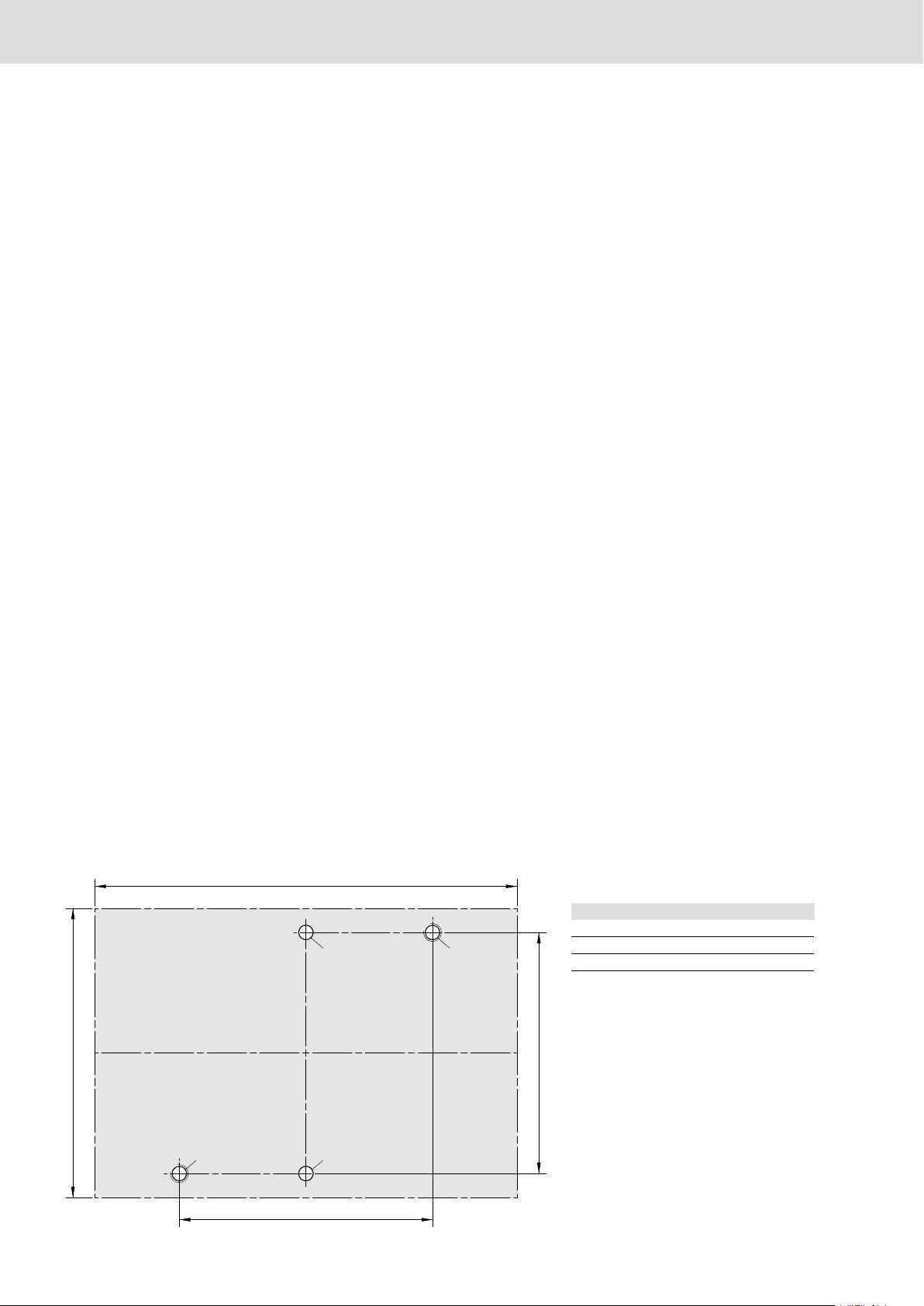
Fig. 4a
“A” [mm] “B” [mm]
PE 1/P-80 25 125
PE 1/P-120 65 165
PE 1/P-160 105 205
"B"
"A"
Ø6F8 M6
Ø6F8
M6
120
100
Zusätzliche Befestigung der
PE 1/P nach unten zur genauen
Vorjustierung über Zylindersstifte l6
und Zylinderschrauben M6x35 auf einer
Tischplatte (Fig. 4)! Bohrbilder siehe Fig.
4a!
Ggf. kann die Verbindungsplatte der
PE 1/P als Bohrschablone verwendet
werden.
Querverbinder QV 1 (unbedingt
erforderlich zur genaueren
Positionierung des WT 1) seitlich in ST
1 (oder BS 1) montieren (Montagemaß
„a“, Fig. 4, unten)!
Bei vorhandenen VE 1 Pneumatik
-anschluss nach innen vorsehen, damit
die Querverbinder soweit wie möglich
an die PE 1/P herangeschoben und
befestigt werden können.
Den Vereinzeler VE 1 vor der PE 1/P
auf der Seite des Positionierzylinders
montieren, um einen besseren
Einlauf des WT 1 in die PE 1/P zu
gewährleisten.
Einstellhinweis für VE 1 Seite 18
beachten!
Additional fastening of the PE 1/P to
the bottom side on a table top for exact
pre-adjustment using l6 cylinder pins
and M6x35 cylinder screws (Fig. 4)! See
figure 4a for hole positions!
If necessary the PE 1/P’s connecting
plate can be used as a drilling template.
Mount QV 1 cross connector (absolutely
needed for exact positioning of the
WT 1) cross-wise in the ST 1 (or BS 1)
(assemble according to “a”, figure 4,
below)!
If a VE 1 is present, pneumatic
connection should be positioned to the
inside, to enable the cross connector
to be shoved up against the PE 1/P
as close as possible and then to be
mounted.
Assemble the VE 1 stop gate on the
positioning cylinder side upstream of the
PE 1/P to ensure better WT 1 entry into
the PE 1/P.
Please follow the setting information
for the VE 1 on page 18!
Fixation supplémentaire de la
PE 1/P vers le bas par des goupilles
cylindriques l6 et des vis à tête
cylindrique M6x35 pour préajustage
exacte sur un plateau de table (Fig. 4) !
Schéma de perçage, voir Fig. 4a !
La plaque de jonction de la PE 1/P peut
éventuellement servir de gabarit de
perçage.
Monter la liaison transversale QV
1 (absolument nécessaire pour le
positionnement exacte de la WT 1)
latéralement dans le section ST 1 (ou
BS 1) (cote de montage „a“, Fig. 4, en
bas) !
Prévoir le raccord pneumatique du VE
1 vers l’intérieur, pour que les liaisons
transversales soient enfoncées le plus
près possible sur la PE 1/P et fixées.
Monter le séparateur VE 1 avant le
PE 1/P sur le côté du cylindre de
positionnement afin de garantir une
meilleure entrée de la WT 1 dans la
PE 1/P.
Respecter la consigne de réglage
pour le VE 1 page 18 !
Montagehinweise!
Assembly instructions!
Conseils pour le montage !

3 842 521 455/2011.04 | TS 1plus Bosch Rexroth AG 11/18
Fig. 4
a
a [mm]
PE 1/P-80 10
PE 1/P-120 30
PE 1/P-160 50
FRANÇAIS DEUTSCH
ENGLISH

12/18 Bosch Rexroth AG TS 1plus | 3 842 521 455/2011.04
Elektrische Anschlüsse nur durch
Fachpersonal!
VDE-Vorschrift VDE 0100.
Näherungsschalter "Y" an Steuerung
anschließen.
Anschlussschema Fig. 6:
Spannung 12 - 30 V =
Schaltstrom max. 100 mA
braun + 24 V =
blau 0 V
schwarz Schaltausgang
Der Schaltabstand ist werkseitig über
LED eingestellt.
Druckluftanschluss „X“
Zur Druckluftaufbereitung ist
eine handelsübliche Wartungseinheit
vorzuschalten!
Geölte oder ungeölte, gereinigte
Druckluft!
Druckluftanschluss „X“ mit Drossel-
rückschlagventil (DRV, abluftgedrosselt),
über Steckfixverbindung (Rohr-Außen
durchmesser 4 mm) mit dem zugehöri-
gen Schaltventil bzw. mit der Wartungs-
einheit verbinden.
Betriebsdruck p: 4 ... 6 bar
Seules des personnes qualifiées sont
autorisées à réaliser les branchements
électriques ! Norme VDE 0100.
Brancher détecteur de proximité "Y" sur
la commande,
Plan des bornes Fig. 6
Tension 12 - 30 V =
Courant de commutation
max. 100 mA
brun + 24 V =
bleu 0 V
noir sortie
L'intervalle de commutation est réglé en
usine par LED.
Branchement d‘air comprimé „X“
Il est nécessaire de placer en amont une
unité de maintenance usuelle pour la
préparation de l‘air comprimé!
Air comprimé, lubrifié ou non, purifié!
Brancher le raccord d‘air comprimé
„X“ à clapet anti-retour à étran-glement
(DRV, à régulation d‘air) à l‘aide du
raccord rapide Steckfix (diamètre
extérieur du tuyau : 4 mm) sur la valve
de commande correspondante voire sur
l‘unité de maintenance.
Pression de service p : 4 ... 6 bars
Electrical connections may only be done
by qualified personnel!
VDE regulation VDE 0100.
Connect proximity switch "Y" to control
unit. Circuit diagram Fig. 6:
Voltage 12 - 30 V =
Max. switching
current 100 mA
Brown + 24 V =
Blue 0 V
Black Switching output
The detection distance is preset at the
factory by means of LED.
Compressed air connection „X“
A standard maintenance unit must be
installed in the air supply line.
Oiled or unoiled, cleaned compressed
air!
Join compressed air connection „X“
containing throttle non-return valve
(DRV, exhaust throttled) to appropriate
switch valve or maintenance unit with
Quickfix snap (outer diameter 4 mm).
Operating pressure p: 4 ... 6 bar
Installation
Installation
Installation

3 842 521 455/2011.04 | TS 1plus Bosch Rexroth AG 13/18
Fig. 6
Fig. 5
1)
2)
3) 4)
+
-
b
a
120
g
d
c
d
FRANÇAIS DEUTSCH
ENGLISH
1) Braun
1) Brown
1) Brun
2) Schwarz
2) Black
2) Noir
3) Blau
3) Blue
3) Bleu
4) Last
4) Load
4) Chargé

14/18 Bosch Rexroth AG TS 1plus | 3 842 521 455/2011.04
Initial operation must be carried out
with proximity switch (S5) mounted in
positioning cylinder (Z3)!
For correct mounting dimensions, only
use stop gate VE 1/P!
(See catalog TS 1: 3 842 521 183)
Function test according to function
plan and Fig. 7.
- Compressed air P, open to 4-6 bar
- Adjustment of throttle non-return
valve (DRV): open 2 to 3 turns!
Safety guards!
After trial run and before initial operation
phase, safety guards must be set up by
the customer to prevent grasping or
reaching in!
Occupational safety guidelines (UVV)
Inbetriebnahme nur mit im
Positionierzylinder (Z3) eingebautem
Näherungsschalter (S5)!
Wegen entsprechender Bauhöhe,
nur Vereinzeler VE 1/P verwenden!
(s. TS 1-Katalog: 3 842 521 183)
Funktionstest nach Funktionsplan
und Fig. 7.
- Druckluft P, 4 bis 6 bar öffnen
- Einstellung Drosselrückschlagventil
(DRV): 2 bis 3 Umdrehungen offen!
Sicherheitseinrichtung!
Nach dem Probelauf und vor der
endgültigen Inbetriebnahme sind
kundenseitig Schutzeinrichtungen gegen
das Hineingreifen anzubringen!
Unfallverhütungsvorschriften (UVV)
Mise en service uniquement avec un
détecteur de proximité (S5) intégré au
cylindre de position-nement (Z3) !
En raison de sa hauteur de construc-
tion, n'utiliser que le séparateur
VE 1/P ! (voir catalogue TS 1 :
3 842 521 183)
Test de fonctionnement
conformément au schéma de
fonctionnement et à la figure 7.
- Air comprimé P : ouvrir sur 4 à 6
bars
- Réglage du clapet anti-retour à
étranglement (DRV) : tourner 2 à 3
fois pour ouvrir !
Dispositif de sécurité !
Après avoir testé le bon fonctionnement
de l‘unité et avant sa mise en service
définitive, le client doit mettre en
place des dispositifs de sécurité pour
empêcher quiconque de passer la main
à l‘intérieur !
Réglementation sur la prévention des
accidents (UVV)
Inbetriebnahme
Initial operation
Mise en service

3 842 521 455/2011.04 | TS 1plus Bosch Rexroth AG 15/18
S4
Z2
S3
S5
S2
VE 1
VE 1
(2/2)
(1/2) Z1
Z3
00108322
1N7
1N6
1N5
1N4
1N3
1N1
1N2
00108323
S3
S2
S3
S4
S4
1N8
S4
1
2
S2
S2
S5
S5
A2
NS Y1 (Z1) S
NS Y2 (Z2)
S Y3 (Z3) R
S Y3 (Z3) S
NS A1
FRANÇAIS DEUTSCH
ENGLISH
Funktionsplan
Function plan
Schéma de fonctionnement
WT Werkstückträger, workpiece pallet, palette porte-pièces
VE Vereinzeler, stop gate, séparateur
1 Startimpuls nach Anlaufende, start pulse after end of approach,
impulsion de départ à la fin du démarrage
2 Freigabe zyklischer Ablauf, enable cyclical sequence, libération des opérations en cycle
A1 Freigabe Werkstück bearbeiten, enable workpiece processing,
libération pour le traitement de la pièce
A2 Quittieren Werkstück bearbeitet, acknowledge workpiece processed, confirmation du traitement de la pièce,
S2 WT arrival, WT nach VE 1/1; WT arrival, WT to VE 1/1; arrivée WT, WT vers VE 1/1
S3 WT in Station, WT vor VE 1/2 einschaltverzögert 150 - 200 ms,
WT in station, WT in front of VE 1/2 switch-on delay 150 - 200 ms,
WT en station, palette avant VE 1/2 allumage retardé de 150 - 200 ms,
S4 Station wird frei, station is free, station libre
S5 WT fixiert, WT fixed, palette fixée
Y1 VE 1/1 öffnen, open VE 1/1, ouvrir VE 1/1
Y2 VE 1/2 öffnen, open VE 1/2, ouvrir VE 1/2
Y3.1/3.2 WT-Fixierung, WT fixation, fixation palette porte-pièces

16/18 Bosch Rexroth AG TS 1plus | 3 842 521 455/2011.04
Déconnecter l’alimentation en
énergie (interrupteur principal etc.)
avant d’entreprendre tous travaux de
maintenance et de réparation ! En outre,
prendre toutes les mesures nécessaires
pour éviter une remise en marche
accidentelle, placer p. ex. un panneau
d'avertissement près de l’interrupteur
principal !
En cas de conditions ambiantes
difficiles, p. ex. milieu très salissant, la
goupille de positionnement du cylindre
pneumatique doit être nettoyée et
lubrifiée une nouvelle fois. Pour cela,
utiliser uniquement des lubrifiants sans
acide ni résine, par exemple du « gleitmo
585M ».
Le remplacement du vérin de
positionnement 3 842 518 633 doit
être effectué après 5 millions de
cycles afin d’atteindre la précision de
positionnement maximale indiquée dans
le catalogue TS 1.
Remplacement du cylindre
pneumatique (Fig. 8)
Débrancher le câble d‘alimentation
électrique du détecteur de proximité et
les raccords pneumatiques.
1 Desserrer deux vis à tête cylindrique
du cylindre
2 le retirer complètement par le haut
avec les goujons d‘assemblage.
3 Fixer le nouveau cylindre
pneumatique.
Rebrancher les raccords électriques et
pneumatiques.
Wartung/Instandsetzung
Maintenance/Repair
Maintenance/Réparation
Before maintenance and repair work
begins, power supplies (mains switches,
etc.) must be turned off! In addition,
measures must be taken to prevent
an inadvertent power switch-on, e.g. a
warning sign at the mains switch!
Under adverse working conditions,
e.g. extreme dirt and dust buildup,
the positioning pin on the pneumatic
cylinder must be cleaned and
relubricated. Use only lubricants free of
acid and resin, e.g. "gleitmo 585M", for
this.
The positioning cylinder
3 842 518 633 must be exchanged after
5 million cycles to reach the maximum
positioning accuracy listed in the TS 1
catalog.
Replacement of pneumatic cylinder
(Fig. 8)
Pull off proximity switch electical
connections and pneumatic couplings.
1 Remove two cylinder screws on
cylinder.
2 Pull off upwards complete with
guide pins.
3 Fasten new pneumatic cylinder.
Restore electrical and pneumatic
connections.
Vor allen Wartungs- und Instand-
setzungsarbeiten Energiezuführungen
(Hauptschalter etc.) abschalten!
Außerdem sind Maßnahmen
erforderlich, um ein unbeabsichtigtes
Wiedereinschalten zu verhindern, z. B.
Warnschild am Hauptschalter anbringen!
Bei erschwerten Umgebungsbe- dingun-
gen, z. B. starkem Schmutzanfall, muss
der Positionierstift am Pneumatik-
zylinder gesäubert und nachgeschmiert
werden. Hierzu nur säure- und harzfreien
Schmierstoff verwenden, z.B. "gleitmo
585M".
Der Austausch des Positionierzylinders
3 842 518 633, ist nach 5 Millionen
Zyklen erforderlich, wenn die maximale
Positioniergenauigkeit lt. TS 1-Katalog
erreicht werden soll.
Austausch Pneumatikzylinder (Fig.8)
Elektrischen Anschluss des
Näherungsschalters und pneumatische
Anschlüsse abziehen.
1 Am Zylinder zwei Zylinderschrauben
lösen
2 komplett mit Führungsstiften nach
oben abnehmen.
3 Neuen Pneumatikzylinder
befestigen.
Elektrische und pneumatische
Anschlüsse wieder herstellen.

3 842 521 455/2011.04 | TS 1plus Bosch Rexroth AG 17/18
Fig. 8
SW 4
5 Nm
gleitmo 585 K
FRANÇAIS DEUTSCH
ENGLISH

Technische Änderungen vorbehalten
Subject to technical modifications
Sous réserve de modifications techniques
Soggetto a modifiche tecniche
Modificaciones técnicas reservadas
Reservado o direito de modificações técnicas
Printed in Germany
Bosch Rexroth AG
Linear Motion and Assembly
Technologies
Postfach 30 02 07
70442 Stuttgart, Germany
DC-IA/MKT
Telefax +49 711 811–7777
www.boschrexroth.com
info@boschrexroth.de
18/18 Bosch Rexroth AG TS 1plus | 3 842 521 455/2011.04
WT [mm] a b c d e f g
WT 1-80 >45 40 **) **) 160 125 62,5
WT 1-120 >65 60 80 50 200 165 82,5
WT 1-160 >85 80 100 70 240 205 102,5
Fig. 9
g
e
b
a
120
g
e
d
c
d
**) Einbaulage vorgegeben
**) Specify installation position
**) Indiquer la position de montage
Hauptabmessungen/Funktionsmaße
Main dimensions/Functional dimensions
Dimensions principales/Dimensions fonctionnelles
nur bei WT 1-80x80!
Only on WT 1-80x80!
seulement pour la WT 1-80x80!
*) Einstellhinweis für VE 1!
Max. Spalt zwischen WT 1 und
VE 1 in Positionierstellung 0,5 mm!
(Maß “b”)
Montagetip:
WT 1 als Distanzlehre verwenden.
*) Setting information for the VE 1!
In the positioning setting, the max.
gap between WT 1 pallet and VE 1
is 0.5 mm! (Measurement “b”)
Assembly tip:
Use WT 1 as a distance gauge.
*) Consigne de réglage pour le VE 1 !
Ecart max. entre la WT 1 et le VE 1
lors du positionnement 0,5 mm !
(Calibre « b »)
Conseil de montage :
Utiliser WT 1 en tant que calibre de
distance.

3 842 521 455/2011.04
Replaces: 2008.05
DE+EN+FR+IT+ES+PT
The Drive & Control Company
3 842 998 101
3 842 998 102
ST 1
PORTUGUÊS ESPAÑOL ITALIANO
Unità di posizionamento PE 1/P
Unidad de posicionamiento PE 1/P
Unidade de posicionamento PE 1/P

2/18 Bosch Rexroth AG TS 1plus | 3 842 521 455/2011.04
Attenzione!
Prima dell‘installazione, la messa in
funzione, la manutenzione e le riparazioni
è necessario leggere e osservare le
istruzioni d‘uso e di montaggio nonché le
“Istruzioni tecniche per la sicurezza dei
lavoratori” (3 842 527 147).
Il lavoro deve essere effettuato solo
da personale tecnico addestrato e
competente!
I collegamenti elettrici devono essere
conformi alle norme vigenti nel paese.
Per la Germania: norma VDE 0100!
Prima di eseguire interventi di
manutenzione o riparazione, spegnere
tutti gli alimentatori di energia
(interruttore principale, ecc.)!
Inoltre è necessario prendere misure per
impedire una riaccensione involontaria,
p. es. apporre un cartello all‘interruttore
principale con la dicitura
„Lavori di manutenzione in corso“,
„Riparazione in corso“ ecc.!
L’unità PE 1/P è stata concepita
per il posizionamento del pezzo sul
pallet Rexroth WT 1 nel sistema di
trasferimento Rexroth TS 1.
Responsabilità:
In caso di danni prodotti da
un‘utilizzazione impropria, o a seguito di
modifiche arbitrarie non previste nelle
presenti istruzioni, decade qualsiasi
garanzia e responsabilità da parte del
fabbricante.
Garanzia:
In caso di mancato utilizzo di parti di
ricambio originali la garanzia non è più
valida!
Lista parti di ricambio MTparts.:
3 842 529 770.
Avvertimenti ecologici:
In caso di sostituzione di parti
danneggiate, provvedere ad una
eliminazione ecologicamente corretta!
¡Atención!
Antes de realizar la instalación,
puesta en servicio, mantenimiento
y reparaciones, leer y respetar
las instrucciones de montaje y
funcionamiento, así como las
“Instrucciones de seguridad técnicas de
los empleados” (3 842 527 147).
¡Las tareas deben ser realizadas tan
sólo por personal técnico capacitado y
competente!
Conexiones eléctricas según las
correspondientes prescripciones
vigentes en cada país. Para Alemania:
Norma VDE 0100.
¡Antes de cualquier trabajo de
reparación o mantenimiento deben
desconectarse todas las alimentaciones
de energía (interruptor principal, etc.)!
¡Además es necesario tomar medidas
para impedir una conmutación
involuntaria, por ejemplo, colocar
un cartel de advertencia „Trabajos
de mantenimiento“, „Trabajos de
reparación“, etc. en el interruptor
principal!
El uso adecuado de la PE 1/P consiste
en colocar la pieza sobre los portapiezas
WT 1 de Rexroth en el sistema transfer
TS 1 de Rexroth.
Avvertenze di sicurezza!
¡Indicaciones de seguridad!
Instruções de segurança!
Other Bosch Valve Positioner manuals
Popular Valve Positioner manuals by other brands

Genebre
Genebre 5952 00 Installation, operation and maintenance manual

Baker Hughes
Baker Hughes Masoneilan 51 Series instruction manual

Bergoz
Bergoz MX-BPM user manual

PI
PI P-73 Series user manual

Bray
Bray Flow-Tek FTG Series Installation, operation and maintenance manual

gefran
gefran POS-MINI SIEIDrive instruction manual

RTK
RTK DAC RE 3581 Series Installation and operating instructions

ABB
ABB FlexPLP IRPLP 220 product manual

Micronix
Micronix PPS-60 Series Reference manual

HART
HART VVP10-H INSTALLATION, OPERATION, CONFIGURATION AND MAINTENANCE MANUAL

Flowserve
Flowserve Logix 3200IQ Replacement instructions

Spirax Sarco
Spirax Sarco SP7-21 quick start guide