manuals.online logo
Brands
  1. Home
  2. •
  3. Brands
  4. •
  5. GEM
  6. •
  7. Valve Positioner
  8. •
  9. GEM 1435 ePos User manual

GEM 1435 ePos User manual

1435
Heating element
for GEMÜ 1435 ePos intelligent positioner
ASSEMBLY INSTRUCTIONS
GB
Heizelement
für intelligenten Stellungsregler GEMÜ 1435 ePos
ORIGINAL MONTAGEANLEITUNG
DE
1435
1 Installing the heating element
1. Isolate the positioner from the pneumatic
control air supply.
2. Loosen the three screws 1 of the base
plate 2and remove them.
3. Apply thermally conductive paste to the
front surface of the temperature sensor 3
to create good heat conduction with the
housing 4.
4. Position the mounting plate 5of the
heating element 6(framed in pink) on the
base plate 2 as illustrated.
5. Attach the mounting plate 5of the
heating element 6 1 to the base plate 2
using the three screws.
6. Press temperature sensor 3against
housing 4, and if necessary bend into
position before installation.
7. Reconnect the positioner to the
pneumatic control air supply.
2 / 4
1 Einbau Heizelement
1 2
3
4
6
5
7
9
8
1. Regler von pneumatischer Hilfsenergie
trennen.
2. Die drei Schrauben 1 der Bodenplatte 2
lösen und entfernen.
3. Frontfläche des Temperaturfühlers 3 mit
Wärmeleitpaste bestreichen, um eine
gute Wärmeleitung mit dem Gehäuse 4
herzustellen.
4. Die Befestigungsplatte 5des
Heizelements 6(pink umrandet) wie
abgebildet auf der Bodenplatte 2
positionieren.
5. Die Befestigungsplatte 5des
Heizelements 6 mit den drei
Schrauben 1 mit der Bodenplatte 2
verschrauben.
6. Temperaturfühler 3an das Gehäuse 4
andrücken, ggf. vor dem Einbau etwas
zurecht biegen.
7. Regler wieder an pneumatische
Hilfsenergie anschließen.
2 Electrical connection
1. Isolate the positioner from the 24 V DC
supply voltage.
2. Guide the two wires 7 of the connection
cable of the heating element 6forwards
to the printed circuit board 9, insert in the
two free soldering points 8 and solder in
place.
The polarity is freely selectable.
3. Connect the 24 V DC supply voltage to
the positioner.
4. Test the performance of the heating
element 6:
• The heating element 6 must switch on
as soon as the temperature sensor 3
measures ≤+5 °C.
• The heating element 6 must switch off
as soon as the temperature sensor 3
measures ≥+15 °C.
3 / 4 1435
2 Elektrischer Anschluss
8
9
1. Regler von Versorgungsspannung
24 V DC trennen.
2. Die beiden Adern 7 der Anschlussleitung
des Heizelements 6nach vorn zur
Leiterplatte 9führen und in die zwei
freien Lötstellen 8 stecken und einlöten.
Die Polarität ist frei wählbar.
3. Versorgungsspannung 24 V DC an den
Regler anlegen.
4. Heizelement 6 auf Funktion prüfen:
• Das Heizelement 6 muss
sich einschalten, sobald der
Temperaturfühler 3≤+5 °C misst.
• Das Heizelement 6 muss
sich abschalten, sobald der
Temperaturfühler 3≥+15 °C misst.
Änderungen vorbehalten · Subject to alteration · 02/2014 · 88424282 
VENTIL-, MESS- UND REGELSYSTEME
VALVES, MEASUREMENT AND CONTROL SYSTEMS
GEMÜ Gebr. Müller Apparatebau GmbH & Co. KG · Fritz-Müller-Str. 6-8 · D-74653 Ingelfingen-Criesbach
Telefon +49(0)7940/123-0 · Telefax +49(0)7940/123-192 · [email protected] · www.gemu-group.com

Other manuals for 1435 ePos

1

Other GEM Valve Positioner manuals

GEM 1434 mPos Assembly instructions

GEM

GEM 1434 mPos Assembly instructions

GEM 1435 ePos User manual

GEM

GEM 1435 ePos User manual

GEM 4242 User manual

GEM

GEM 4242 User manual

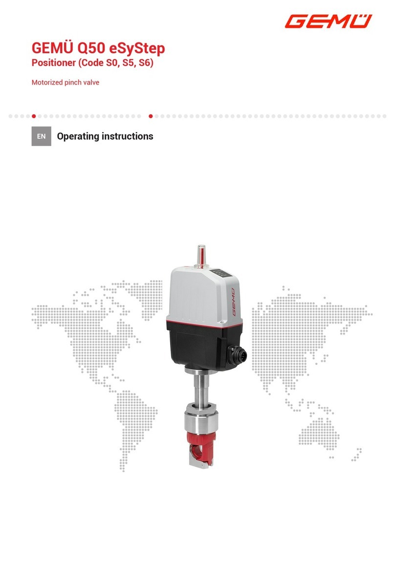
GEM eSyStep Q50 User manual

GEM

GEM eSyStep Q50 User manual

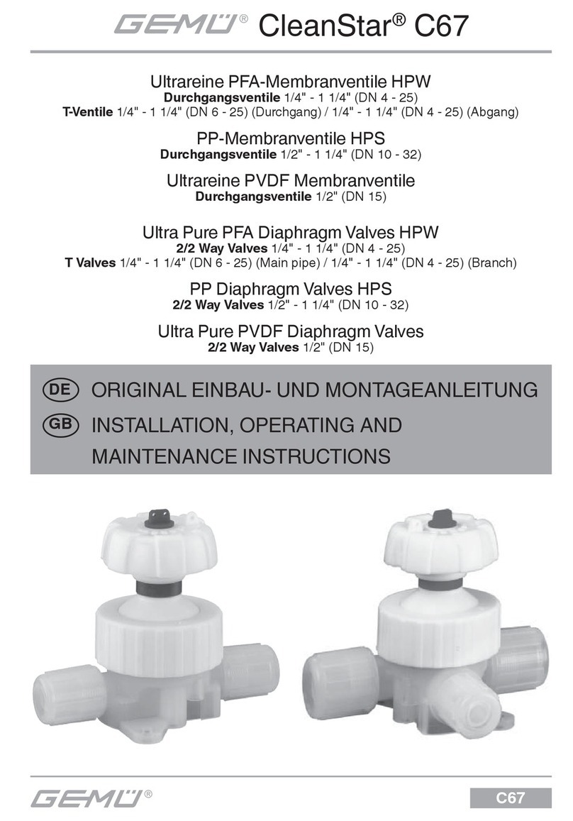
GEM C67 CleanStar User guide

GEM

GEM C67 CleanStar User guide

GEM 1434 mPos User manual

GEM

GEM 1434 mPos User manual

GEM 650 Assembly instructions

GEM

GEM 650 Assembly instructions

GEM Q40 User manual

GEM

GEM Q40 User manual

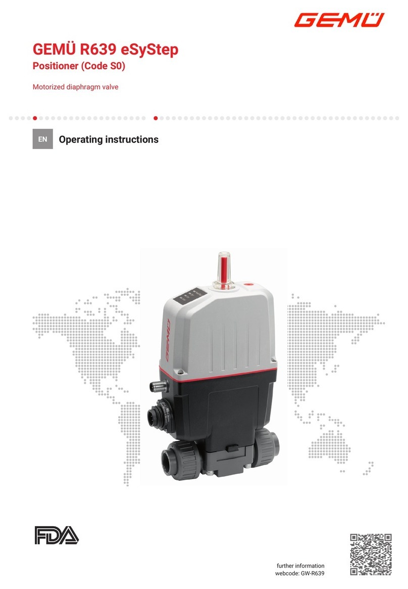
GEM R639 User manual

GEM

GEM R639 User manual

GEM 543 eSyStep User manual

GEM

GEM 543 eSyStep User manual

GEM 1441 cPos-X User manual

GEM

GEM 1441 cPos-X User manual

GEM 1434 mPos Assembly instructions

GEM

GEM 1434 mPos Assembly instructions

GEM 543 eSyStep User manual

GEM

GEM 543 eSyStep User manual

GEM 1441 cPos-X User manual

GEM

GEM 1441 cPos-X User manual

GEM 1436 cPos User manual

GEM

GEM 1436 cPos User manual

GEM 533 User manual

GEM

GEM 533 User manual

Popular Valve Positioner manuals by other brands

Samson 3730-2 Mounting and operating instructions

Samson

Samson 3730-2 Mounting and operating instructions
Ytc YT-2300 Series user manual

Ytc

Ytc YT-2300 Series user manual

ProArc PT-1000 owner's manual

ProArc

ProArc PT-1000 owner's manual

rotork TMP-3000 product manual

rotork

rotork TMP-3000 product manual

Vector MZ3-FA-V11 manual

Vector

Vector MZ3-FA-V11 manual

KMC Controls CMC-1001 installation guide

KMC Controls

KMC Controls CMC-1001 installation guide

Siemens SIPART PS2 Technical description

Siemens

Siemens SIPART PS2 Technical description

Flowserve APEX W8000 Installation operation & maintenance

Flowserve

Flowserve APEX W8000 Installation operation & maintenance

Burkert 1067 manual

Burkert

Burkert 1067 manual

halstrup-walcher PSD4 Series instruction manual

halstrup-walcher

halstrup-walcher PSD4 Series instruction manual

STI SA/CL instruction manual

STI

STI SA/CL instruction manual

Vestil MWP-220 instruction manual

Vestil

Vestil MWP-220 instruction manual

VAC V200 Series Installation, operation and maintenance

VAC

VAC V200 Series Installation, operation and maintenance

YASKAWA MH SIGMA-5 Series manual

YASKAWA

YASKAWA MH SIGMA-5 Series manual

NBK EPU-220 instruction manual

NBK

NBK EPU-220 instruction manual

RTK RE3447 Series Installation and operating instructions

RTK

RTK RE3447 Series Installation and operating instructions
Flowserve Logix 520si Series User instructions

Flowserve

Flowserve Logix 520si Series User instructions

Parker Daedal 412T01LXR product manual

Parker

Parker Daedal 412T01LXR product manual

manuals.online logo
manuals.online logoBrands
  • About & Mission
  • Contact us
  • Privacy Policy
  • Terms and Conditions

Copyright 2025 Manuals.Online. All Rights Reserved.