4/16
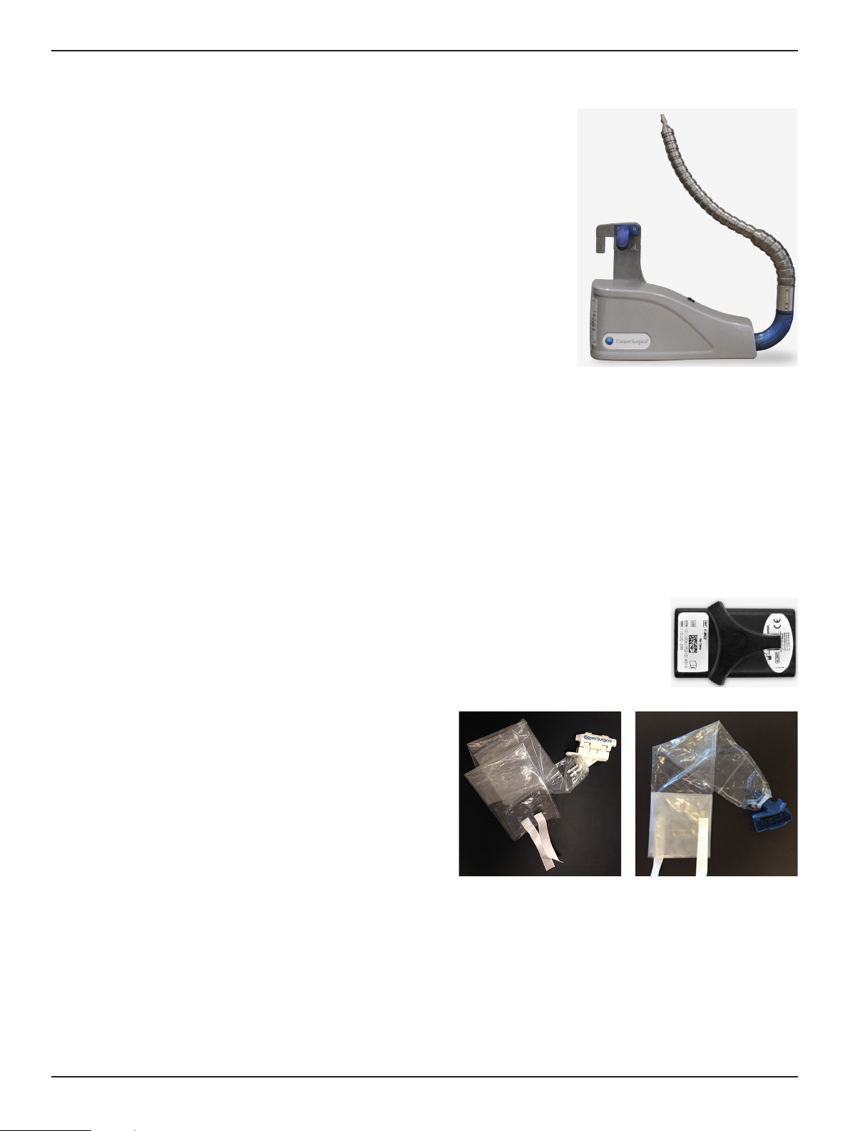
ALLY II UPS™
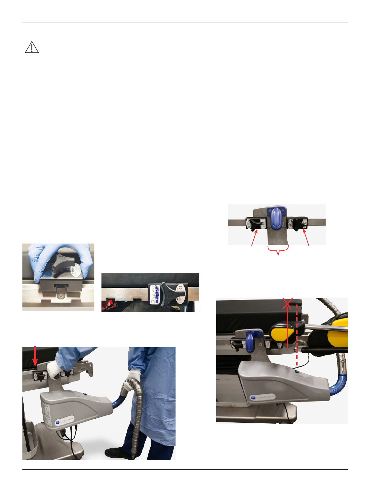
• Do not install rail clamp across separated rail sections.
• Surgical procedures requiring vaginal instrumentation are not sterile. Conventional Operating Room procedures for
maintaining sterility must be observed when the ALLY II UPS™ is in use.
• DO NOT USE EXCESSIVE FORCE. If adequate range of motion is not obtained, reposition the ALLY II UPS™
(reference section 12.2 on proper positioning). If problem persists, discontinue use.
• DO NOT store the device in direct sunlight, at high temperatures or high humidity.
• DO NOT store this device in the shipping box.
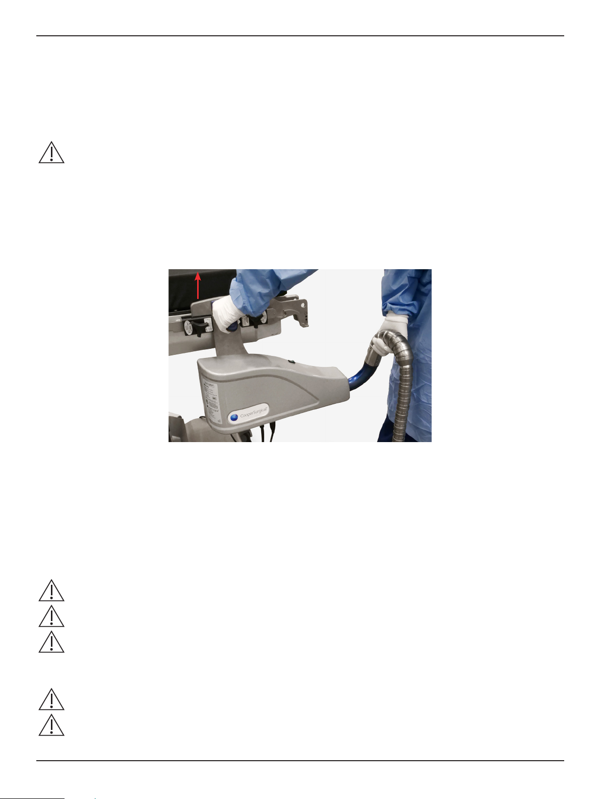
• ALWAYS position the patient and the operating room table prior to attaching the ALLY II UPS™ to the manipulator.
• ALWAYS have patient under general endotracheal anesthesia when ALLY II UPS™ is attached to the manipulator.
• ALWAYS use caution when attaching and detaching the manipulator from the ALLY II UPS™.
• DO NOT move the foot end of the Operating Room table while the ALLY II UPS™ is attached to the table.
• ALWAYS follow all instructions discussed in the Uterine Manipulator Instructions for Use.
• ALWAYS handle the ALLY II UPS™ with care. Avoid mechanical shock or stress that can cause damage to the
device.
• DO NOT carry the ALLY II UPS™ using anything other than the handle and arm. The foot pedal cover should be
used to lift, carry, or reposition the foot pedal.
• The ALLY II UPS™ is not designed for use in environments in which strong Electromagnetic interference (EMI) may
impact the performance of the equipment.
The emissions characteristics of this equipment make it suitable for use in industrial areas and hospitals (CISPR 11
class A). If it is used in a residential environment (for which CISPR 11 class B is normally required) this equipment
might not oer adequate protection to radio-frequency communication services. The user might need to take
mitigation measures, such as re-locating or re-orienting the equipment.
If this occurs, the site of use should be surveyed to determine the source of this disruption, and the following actions
may be taken to eliminate the source:
-Remove, re-orient or re-locate the interfering equipment.
-Increase the separation between the interfering equipment and the ALLY II UPS™.
-Incrementally turn o equipment in the vicinity to identify the interfering device.
PRECAUTIONS:
• Always ensure that the ALLY II UPS™ is tightly and securely attached to the table prior to the start of the surgical
procedure. Improper or loose mounting of the system can lead to unintended movement and may lead to injury.
• Inspect the adapter drape prior to use for damage. Ensure that the packaging of the adapter drape has not been
breached. Verify the expiration date.
• Operating room personnel should take care not to contaminate the draped ALLY II UPS™ during the remaining
patient preparation steps.
•DO NOT attach the manipulator to the ALLY II UPS™ arm until after the da Vinci®Surgical System patient side cart
is in position and the brakes are set.
•DO NOT attach the manipulator to the ALLY II UPS™ arm until after the patient is in the nal position.
• Users should check that the adapter is holding the manipulator securely without any extraneous movement prior to
operative use. If the manipulator does not securely attach to the manipulator adapter discontinue use immediately.
• The ALLY II UPS™ MUST be removed from the table PRIOR to the foot end/pins being returned to the horizontal
position.
• Damage will result if the exible arm is cleaned with bleach products.
• Damage may result if the rail clamp is cleaned with bleach.
• Care should be taken during storage and transportation to avoid drops, falls, mechanical stress, and mechanical
shock to the device.
9.1 REQUIREMENTS APPLICABLE TO THE ALLY II UPS™
The ALLY II UPS™ needs special precautions regarding EMC and needs to be installed and put into service according
to EMC information provided in the tables in Sections 13 through 16.
Portable and mobile RF communications equipment can aect the ALLY II UPS™.
SECTION 10 ADVERSE EVENTS
PLEASE NOTE: If a serious incident is suspected from using the ALLY II UPS™, report the details of the incident to
CooperSurgical
via
phone
number
+1
203-601-5200
Ext
3100
or
by
email
at
[email protected] and to the local Health Authority in your area. A serious incident may have caused or contributed to a death, a delay in a
procedure which resulted in death or serious injury, or a malfunction that could have caused an adverse event.