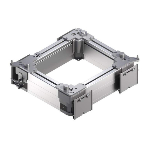
Bosch Rexroth PE 2/XP User manual

PE 2/XH
PE 2/XP
3 842 523 895/2015-02
Replaces: –
DE+EN+FR+IT+ES
Montageanleitung • Assembly instructions • Instructions de montage
Istruzioni per il montaggio • Instrucciones de montaje
Positioniereinheit PE 2/XP
PE 2/XP Positioning unit
Unité de positionnement PE 2/XP
Unità di posizionamento PE 2/XP
Unidad de posicionamiento PE 2/XP
523895_2015_02.indd 1523895_2015_02.indd 1 19.02.2015 13:17:4919.02.2015 13:17:49

2/32 Bosch Rexroth AG TS 2plus | 3 842 523 895/2015-02
Sicherheitshinweise!
Safety instructions!
Conseils de sécurité !
Avvertenze di sicurezza!
¡Indicaciones de seguridad!
Die Installation, Inbetriebnahme, War-
tung und Instandsetzung, darf nur unter
Berücksichtigung aller Sicherheitshin-
weise und -Vorschriften und nur durch
geschultes, eingewiesenes Fachperso-
nal durchgeführt werden!
Alle Sicherheitsabdeckungen, die bei
Wartungsarbeiten entfernt wurden,
müssen vor der Inbetriebnahme wieder
angebracht werden!
Elektrische Anschlüsse nach der ent-
sprechenden nationalen Vorschrift. Für
Deutschland:
VDE-Vorschrift VDE 0100!
Vor allen Instandsetzungs-, und
Wartungsarbeiten sind die Ener-
giezuführungen (Hauptschalter,
Druckminderventil etc.) abzuschal-
ten! Außerdem sind Maßnahmen
erforderlich, um ein unbeabsichtigtes
Wiedereinschalten zu verhindern, z. B.
am Hauptschalter ein entsprechendes
Warnschild „Wartungsarbeiten“, „In-
standsetzungsarbeiten“ etc. anbringen!
Die bestimmungsgemäße Verwendung
der PE 2/XP ist das Anheben und Posi-
tionieren von Werkstückträgern (WT 2)
im Rexroth-Transfersystem TS 2plus.
Haftung:
Bei Schäden, die aus nicht bestim-
mungsgemäßer Verwendung und aus
eigenmächtiger, in dieser Anleitung nicht
vorgesehenen Eingriffen entstehen,
erlischt jeglicher Gewährleistungs- und
Haftungsanspruch gegenüber dem
Hersteller.
Gewährleistung:
Bei Nichtverwendung von
Originalersatzteilen erlischt der Gewähr-
leistungsanspruch!
Ersatzteilliste MTparts:
3 842 529 770.
Umweltschutz:
Beim Austausch von Schadteilen ist
auf eine sachgerechte Entsorgung zu
achten!
Abkürzungen:
PE 2/XP = Positioniereinheit
WT 2 = Werkstückträger TS 2
ST 2 = Strecke ST 2
Installation, initial operation, maintenance
and repair work may only be carried out
in accordance with the relevant safety
instructions and regulations and only by
qualified and specially trained personnel!
All security coverings that have been
removed during repair works have to be
reinstalled before initial operation!
All electrical connections must be made
in accordance with the applicable natio-
nal regulations. For Germany: regulation
VDE 0100
(VDE, German Association of Electri-
cians)!
The power supply must always be
switched off (at main switch, pressure
relief valve etc.) before maintenance and
repair work!
Take precautions to prevent inadvertent
restoration of power, e.g. by hanging a
suitable warning sign at the main switch,
such as:
“Maintenance work in progress“, or
“Repair work in progress“!
The PE 2/XP is intended to be used for
lifting the workpiece pallet (WT 2) in the
Rexroth transfer system TS 2plus.
Liability:
In no event can the manufacturer accept
warranty claims or liability claims for
damages arising from improper use of
the appliance or from intervention in the
appliance other than that described in
this Instruction Manual.
Warranty:
The manufacturer can accept no claims
for warranty arising from the use of non-
original spare parts!
MTparts spare parts list:
3 842 529 770.
Environmental protection:
Always dispose of damaged parts in the
correct manner when replacement work
is complete!
L’installation, la mise en service, la main-
tenance et les réparations ne peuvent
être effectuées que par des personnes
agréées et compétentes et en respec-
tant les conseils de sécurité!
Avant la mise en service, remettre en
place tous les carters de sûreté enlevés
pour les travaux de maintenance !
Les branchements électriques doivent
être conformes à la réglementation
nationale. Pour l’Allemagne : norme
VDE 0100!
Avant d’effectuer des réparations ou
des travaux de maintenance, couper
l’alimentation en énergie (interrupteur
principal, mano-détendeur etc.)!
D’autre part, prendre toutes les mesures
nécessaires pour éviter une remise en
marche accidentelle, en apposant par
exemple près de l’interrupteur principal
un panneau d’avertissement „Travaux de
maintenance“, „Réparations“
etc.!
L’utilisation conforme du PE 2/XP est la
levée et le positionnement des palettes
porte-pièces (WT 2) dans le système de
transfert Rexroth TS 2plus.
Responsabilité :
le fabricant décline toute responsabilité
et exclut toute réclamation concernant
les dommages dus à une utilisation non
conforme ou suite à des modifications
effectuées sans autorisation et non
prévues ci-contre.
Garantie :
En cas de non-utilisation des pièces dé-
tachées d‘origine, le constructeur exclut
toute responsabilité !
Liste des pièces détachées MTparts :
3 842 529 770.
Protection de l’environnement :
Veiller à ce que les pièces endom-
magées soient éliminées en toute
conformité !
Abbreviations:
PE 2/XP = Positioning unit
WT 2 = Workpiece pallet TS 2
ST 2 = Conveyor section ST 2
Abréviations:
PE 2/XP = Unité de positionnement
WT 2 = Palette porte-pièces TS 2
ST 2 = Section ST 2
523895_2015_02.indd 2523895_2015_02.indd 2 19.02.2015 13:17:5419.02.2015 13:17:54

3 842 523 895/2015-02 | TS 2plus Bosch Rexroth AG 3/32
¡La instalación, la puesta en funcio-
namiento, el mantenimiento y las
reparaciones deben realizarse tomando
en cuenta las indicaciones y prescrip-
ciones de seguridad y sólo por personal
técnico capacitado y competente!
¡Todos los recubrimientos de seguridad
retirados durante los trabajos de mante-
nimiento deben volver a colocarse antes
de la puesta en funcionamiento!
¡Conexiones eléctricas según las corre-
spondientes prescripciones vigentes en
cada país. Para Alemania: Norma VDE
0100!
¡Antes de cualquier trabajo de re-
paración o mantenimiento deben
desconectarse todas las alimentaciones
de energía (interruptor principal, válvula
reductora de presión, etc.)!
¡Además es necesario tomar medidas
para impedir una conmutación involun-
taria, por ejemplo, colocar un cartel de
advertencia „Trabajos de mantenimien-
to“, „Trabajos de reparación“, etc. en el
interruptor principal!
La utilización prevista de la PE 2/XP es
la elevación y el posicionamiento de
los portapiezas (WT 2) en el sistema de
transporte Rexroth TS 2plus.
Responsabilidad:
En caso de daños producidos por la
utilización inadecuada y por acciones
arbitrarias no previstas en estas in-
strucciones, caduca toda garantía o
responsabilidad por parte del fabricante.
Garantía:
En caso de no utilizarse piezas de re-
cambio originales caduca la garantía.
Lista de piezas de recambio MTparts:
3 842 529 770.
Protección ambiental:
¡Al cambiar piezas dañadas debe
tenerse en cuenta una eliminación
ecológicamente correcta!
L’installazione, la messa in funzione,
la manutenzione e le riparazioni vanno
eseguite nel rispetto di tutte le avverten-
ze e norme di sicurezza e devono essere
effettuate solo da personale tecnico
qualificato ed addestrato!
Tutte le coperture di sicurezza, che sono
state rimosse in occasione di lavori di
manutenzione, devono essere ripristinate
prima della messa in funzione!
I collegamenti elettrici devono essere
conformi alle norme vigenti nel rispettivo
paese. Per la Germania: norma VDE
0100!
Prima di eseguire interventi di manuten-
zione o riparazione, spegnere tutti gli
alimentatori di energia (interruttore prin-
cipale, valvola riduttrice della pressione
ecc.)!
Inoltre è necessario prendere misure
per impedire una riaccensione involon-
taria, p. es. apporre un cartello accanto
all’interruttore principale con la dicitura
“Lavori di manutenzione in corso“, „Ripa-
razione in corso“ ecc.!
L‘PE 2/XP è preposto al sollevamento e
al posizionamento dei portapezzi (WT 2)
nel sistema di trasferimento TS 2plus
della Rexroth.
Responsabilità:
In caso di danni prodotti da un’uso
improprio, o a seguito di modifiche
arbitrarie - non previste nelle presenti
istruzioni - decade qualsiasi garanzia e
responsabilità da parte del fabbricante.
Garanzia:
In caso di mancato utilizzo di parti di
ricambio originali la garanzia non è più
valida!
Lista parti di ricambio MTparts.:
3 842 529 770.
Avvertimenti ecologici:
In caso di sostituzione di parti dann-
eggiate, provvedere ad uno smaltimento
ecologicamente corretto!
Abreviaturas:
PE 2/XP = unidad de posicionam.
WT 2 = portapiezas TS 2
ST 2 = tramo ST 2
Abbreviazioni:
PE 2/XP = Unità di posizionamento
WT 2 = Portapezzo TS 2
ST 2 = Tratto ST 2
523895_2015_02.indd 3523895_2015_02.indd 3 19.02.2015 13:17:5419.02.2015 13:17:54

Fig. 1
WT 2
b *)
PE 2/XH
ST 2
PE 2/XP
4/32 Bosch Rexroth AG TS 2plus | 3 842 523 895/2015-02
Einführung/Baugrößen
Introduction/Dimensions
Introduzione/Dimensioni
Introducción/Tamaños
Die Positioniereinheit PE 2/XP
- hebt Werkstückträger WT 2 von der
Bandstrecke (Arbeitsstellung) oder
- läßt die WT 2 passieren
(Ruhestellung).
Die Positioniereinheit kann Prozeßkräf-
te F, z. B. beim Einpressen oder Nieten,
aufnehmen:
- Baugröße I (BG I)
b = 160 mm, max. 60 kN
- Baugröße II (BG II)
b = 240 mm, max. 100 kN
*) Die WT-Abmessung in Transportrichtung
lTund die Spurbreite b entsprechen, je
nach Einbaurichtung den WT-Abmessun-
gen lWT bzw. bWT
The PE 2/XP positioning unit
- lifts workpiece pallets WT 2 from
the conveyor belt section (operating
position) or
- lets the WT 2 pass by
(neutral position).
The positioning unit can absorb proce-
dural forces such as during pressing-in
or riveting:
- Size I (BG I)
b = 160 mm, max. 60 kN
- Size II (BG II)
b = 240 mm, max. 100 kN
*) The WT dimensions in the direction of
transport lTand track width b are equal to
WT dimensions lWT or bWT , respectively.
L’unité de positionnement PE 2/XP
- soulève des palettes porte-pièces
WT 2 de la section à bande (position
de travail) ou
- laisse passer les WT 2
(position de repos).
L’unité de positionnement peut être
soumise à des efforts F, p. ex. lors de
l’emmanchement ou du rivetage :
- Dimension I (BG I)
b = 160 mm, max. 60 kN
- Dimension II (BG II)
b = 240 mm, max. 100 kN
*) La dimension du WT dans le sens de
transport lTet la largeur de voie b corre-
spondent, selon le sens d’installation aux
dimensions du WT lWT ou bWT
523895_2015_02.indd 4523895_2015_02.indd 4 19.02.2015 13:17:5419.02.2015 13:17:54

Fig. 2
PE 2/XP
BG I
3 842 242 350
F
b *)
BG II
3 842 242 351
F
b *)
3 842 523 895/2015-02 | TS 2plus Bosch Rexroth AG 5/32
L‘unità di posizionamento PE 2/XP
- solleva i portapezzi WT 2 dal tratto a
nastro (posizione di lavoro) oppure
- consente il loro oltrepassaggio (WT 2)
(posizione di riposo).
L‘unità di posizionamento può assorbire
forze di processo F, p. es. nell‘incorporo
a stampaggio oppure nella rivettatura:
- Dimensione I (BG I)
b = 160 mm, max. 60 kN
- Dimensione II (BG II)
b = 240 mm, max. 100 kN
*) Le dimensioni del WT nel senso di
marcia lTe la larghezza del tratto b cor-
rispondono, a seconda della direzione di
montaggio, alle dimensioni del WT lWT
oppure bWT
La unidad de posicionamiento PE 2/XP
- eleva portapiezas WT 2 desde el
tramo de cinta (posición de trabajo) o
- deja pasar a los WT 2
(posición de reposo).
La unidad de posicionamiento puede
tomar cargas de proceso F, por ej. al
prensar o remachar:
- Tamaño I (BG I)
b = 160 mm, máx. 60 kN
- Tamaño II (BG II)
b = 240 mm, máx. 100 kN
*) La dimensión del WT en el sentido de
transporte lTy el ancho de vía b corre-
sponden, según el sentido de montaje, a
las dimensiones del WT lWT o bien bW
523895_2015_02.indd 5523895_2015_02.indd 5 19.02.2015 13:17:5419.02.2015 13:17:54

Fig. 3
2 x
4 x
2 x
6 x
8 m6 x 20
M8 x 25
M8 x 30
8-Fst
DIN 6325
DIN 912
DIN 912
A
B
D
C
DIN 6798
BG I
3 842 242 350
PE 2/XH
BG II
3 842 242 351
PE 2/XP
6/32 Bosch Rexroth AG TS 2plus | 3 842 523 895/2015-02
Anlieferzustand/Lieferumfang
Condition on delivery/Scope of delivery
Etat à la livraison/Fournitures
Stato alla consegna/Fornitura
Estado de entrega/Volumen del suministro
Die PE 2/XP wird komplett montiert
geliefert. Die Befestigungselemente sind
lose beigepackt.
Hinweis:
Je nach Einbausituation ist kundenseitig
eine entsprechende Schutzeinrichtung
vorzusehen.
The PE 2/XP is delivered fully assem-
bled. The attachment elements are
packed loosely.
Note:
An appropriate protective enclosure is to
be provided by the customer according
to the installation situation.
La PE 2/XP est livrée entièrement mon-
tée. Les éléments de fixation sont livrés
démontés.
Remarque:
Selon l’installation, le client doit prévoir
un dispositif de protection adéquat.
Il PE 2/XP viene fornito completamente
montato. Gli elementi di fissaggio sono
forniti sciolti in imballo a parte.
Avvertenza:
A seconda delle condizioni in cui si
esegue il montaggio il cliente dovrà pro-
vvedere alle adeguate protezioni.
La PE 2/XP se entrega completamente
montada. Los elementos de fijación se
entregan por separado.
Indicación:
Según la condición de montaje, el
cliente debe prever el correspondiente
dispositivo protector.
523895_2015_02.indd 6523895_2015_02.indd 6 19.02.2015 13:17:5419.02.2015 13:17:54

30
39
30
39
Ambossplatte
Anvil plate
Plaque enclume
Piastra incudine
Placa del yunque
Bestell-Nr. (für Ambossplatte)
Order no. (for anvil plate)
N° de commande (pour plaque enclume)
Codice ord. (per piastra incudine)
N° de pedido (para placa del yunque)
lT[mm] b [mm] BG I BG II
160 160 3 842 242 375 ---
240
160
240
240
240
320
3 842 242 376
3 842 242 376
3 842 242 377
3 842 242 378
3 842 242 390
3 842 242 395
---
---
---
---
3 842 523 895/2015-02 | TS 2plus Bosch Rexroth AG 7/32
Optionales Zubehör
Optional accessories
Accessoires en option
Accessori facoltativi
Accesorios opcionales
Das optionale Zubehör ist separat zu
bestellen.
- Endlagenabfrage: ein oder zwei Nähe-
rungsschalter
EN 60947-5-2-l2 A12
- Ambossplatte: WT-abhängig, in vier
Standardgrößen oder Kundenspezi-
fisch (s. Bohrbild, Seite 9)
- Positionierstift rund,
Positionierstift abgeflacht;
Verwendung jeweils in Verbin-
dung mit der Standard-Ambossplatte
Les accessoires en option doivent être
commandés séparément.
- Détection de position finale: un ou
deux détecteurs de proximité
EN 60947-5-2-l2 A12
- Plaque enclume: en foction du WT, en
quatre tailles standard ou personnali-
sée (cf. gabarit de perçage, page 9)
- Tige de positionnement ronde,
Tige de positionnement aplatie;
à utiliser respectivement avec la
plaque enclume standard
The optional accessories are to be orde-
red separately.
- End position sensing: one or two
proximity switches
EN 60947-5-2-l2 A12
- Anvil plate: WT-dependent, in four
standard sizes or custom (see drilling
plan, page 9)
- Round positioning pin,
flattened positioning pin;
used respectively in connection with
the standard anvil plate
Los accesorios opcionales deben pedir-
se por separado.
- Consulta de posición final: uno o dos
interruptores de aproximación
EN 60947-5-2-l2 A12
- Placa del yunque: según los WT, en
cuatro tamaños estándar o especial
para el cliente (ver esquema de talad-
ros, pág. 9)
- Pasador de posicionamiento redondo,
pasador de posicionamiento aplana-
do;
utilización en cada caso junto
con la aplaca del yunque estándar.
Gli accessori facoltativi dovranno essere
ordinati a parte.
- Interrogazione posizione finale: uno o
due interruttori di prossimità
EN 60947-5-2-l2 A12
- Piastra incudine: in quattro grandezze
standard in relazione al WT oppure a
richiesta del cliente (schema di foratu-
ra, v. pag. 9)
- Spina di posizionamento, rotonda
Spina di posizionamento, appiattita
L‘utilizzo avverrà rispettivamente in
unione con la piastra incudine stan-
dard.
523895_2015_02.indd 7523895_2015_02.indd 7 19.02.2015 13:17:5519.02.2015 13:17:55

WT 2 PE 2/XH
lWT lWT
ST 2
21
213
Fig. 4
PE 2/XP
1
3 842 211 354
23
8/32 Bosch Rexroth AG TS 2plus | 3 842 523 895/2015-02
Optionales Zubehör (Forts.)
Optional accessories (cont.)
Accessoires en option (suite)
Accessori facoltativi (cont.)
Accesorios opcionales (cont.)
Teilesatz für WT-Durchlauf-steue-
rung 3 842 211 354
bestehend aus:
1 Vereinzeler VE 2 (2x)
2 Schalterhalter SH 2/UV (2x)
3 Schalterhalter SH 2/S (1x)
Elektrische Näherungsschalter
EN 60947-5-2-l2 A12 sind nicht im
Lieferumfang enthalten (bitte separat
bestellen).
Kit per il controllo del passaggio del
WT 3 842 211 354
costituito da:
1 singolarizzatore VE 2 (2x)
2 supporto interruttore SH 2/UV (2x)
3 supporto interruttore SH 2/S (1x)
Gli interruttori di prossimità elettrici
EN 60947-5-2-l2 A12 non sono forniti in
dotazione (si prega di ordinarli a parte).
Juego de piezas para comando de
pasaje WT 3 842 211 354
consistente en:
1 separador VE 2 (2x)
2 soporte de interruptor SH 2/UV (2x)
3 soporte de interruptor SH 2/S (1x)
Los interruptores de aproximación
eléctricos EN 60947-5-2-l2 A12 no se
incluyen en el volumen del suministro
(pedir por separado).
Parts kit for WT pass-through con-
trol 3 842 211 354
consists of:
1 stop gate VE 2 (2x)
2 switch bracket SH 2/UV (2x)
3 switch bracket SH 2/S (1x)
Electric proximity switches EN 60947-5-
2-l2 A12 are not included in the scope
of delivery (please order separately).
Jeu de pièces pour commande de
passage du WT 3 842 211 354
comprenant:
1 séparateur VE 2 (2x)
2 supports d’interrupteur SH 2/UV (2x)
3 supports d’interrupteur SH 2/S (1x)
détecteur électrique de proximité
EN 60947-5-2-l2 A12 ne sont pas com-
pris dans les fournitures (à commander
séparément).
523895_2015_02.indd 8523895_2015_02.indd 8 19.02.2015 13:17:5519.02.2015 13:17:55

Fig. 5
Fig. 6
3(3 842 242 391), 4(3 842 242 396)
3
21
WT 2
9
lT[mm]b [mm]
160 160 322
240
160
240
320
240
78,5
118,5
158,5
78,5
405
270
350
40±0,2
100±0,2
A [mm] B [mm] C [mm] D [mm]
C *)
==
A
B10
D
M8
M8
ø 8H7
b
b-80
3 842 523 895/2015-02 | TS 2plus Bosch Rexroth AG 9/32
Montage: Bohrbilder für Befestigung
Assembly: drilling plan for attachment
Montage : gabarit de perçage pour fixation
Montaggio: Schemi di foratura per il fissaggio
Montaje: esquema de taladros para fijación
Bohrbild für die Befestigung des Unter-
teils nach Fig. 5 + Tabelle herstellen.
Bohrbild des Oberteils (BG II) für kun-
denspezifische Positionier- und Amboss-
platten (verkürzte Positionier-stifte 3 und
4 verwenden) nach Fig. 6.
Ejecutar el esquema de taladros para la
fijación de la parte inferior según Fig. 5
+ Tabla.
Esquema de taladros de la parte supe-
rior (BG II) para placas de posicionami-
ento y del yunque específicas del cliente
(utilizar los pasadores de posicionamien-
to acortados 3 y 4) según Fig. 6.
Realizzare i fori per il fissaggio del pezzo
inferiore in base alla Fig. 5 + Tabella.
Schema di foratura del pezzo superiore
(BG II) per piastre di posizionamento e
incudine a richiesta in base alla Fig. 6
(utilizzare le spine di posizionamento più
corte 3 e 4)
Faire un gabarit de perçage pour fixer
la partie inférieure selon la Fig. 5 +
Tableau.
Gabarit de perçage de la partie supé-
rieure (BG II) pour plaques de posi-
tionnement et enclume personnalisées
(utiliser des tiges de positionnement
plus courtes 3 et 4 ) selon la Fig. 6.
Make the drilling plan for attaching the
lower section according to fig. 5 and the
table.
Upper section (BG II) drilling plan for
custom positioning and anvil plates (use
shortened positioning pins) according
to fig. 6.
*)WT-Mitte, *) WT center, *) Milieu du WT,
*)centro del WT, *) centro del WT
523895_2015_02.indd 9523895_2015_02.indd 9 19.02.2015 13:17:5519.02.2015 13:17:55

Fig. 7
2
3
4
1
5
6
7
9
11
12
10
8
10/32 Bosch Rexroth AG TS 2plus | 3 842 523 895/2015-02
Montage, Einbau
Assembly, installation
Assemblage, montage
Montaggio, assemblaggio
Montaje, ensamblaje
523895_2015_02.indd 10523895_2015_02.indd 10 19.02.2015 13:17:5519.02.2015 13:17:55

3 842 523 895/2015-02 | TS 2plus Bosch Rexroth AG 11/32
1 Positioniereinheit PE 2/XP
2 Strecke ST 2
3 Ambossplatte
4 Positionierstift, rund
5 Positionierstift, abgeflacht
6 Vorvereinzeler VE1
7 Hauptvereinzeler VE2
8 Näherungsschalter S 1mit Schalter-
halter SH 2/UV
9 Näherungsschalter S2
mit Schalterhalter SH 2/S
10 Näherungsschalter S3
mit Schalterhalter SH 2/UV
11 Näherungsschalter S4
12 Näherungsschalter S5
1 Positioning unit PE 2/XP
2 Conveyor section ST 2
3 Anvil plate
4 Positioning pin, round
5 Positioning pin, flattened
6 Preliminary stop gate VE1
7 Main stop gate VE2
8 Proximity switch S1
with switch bracket SH 2/UV
9 Proximity switch S2
with switch bracket SH 2/S
10 Proximity switch S3
with switch bracket SH 2/UV
11 Proximity switch S4
12 Proximity switch S5
1 Unité de positionnement PE 2/XP
2 Section ST 2
3 Plaque enclume
4 Tige de positionnement, ronde
5 Tige de positionnement, aplatie
6 Pré-séparateur VE1
7 Séparateur principal VE2
8 Détecteur de proximité S1
avec support d’interrupteur SH 2/UV
9 Détecteur de proximité S2
avec support d’interrupteur SH 2/S
10 Détecteur de proximité S3
avec support d’interrupteur SH 2/UV
11 Détecteur de proximité S4
12 Détecteur de proximité S5
1 Unità di posizionamento PE 2/XP
2 Tratto ST 2
3 Piastra incudine
4 Spina di posizionamento, rotonda
5 Spina di posizionamento, appiattita
6 Pre-singolarizzatore VE1
7 Singolarizzatore principale VE2
8 Interr. di prossimità S1
con supporto SH 2/UV
9 Interr. di prossimità S2
con supporto SH 2/S
10 Interr. di prossimità S3
con supporto SH 2/UV
11 Interr. di prossimità S4
12 Interr. di prossimità S5
1 Unidad de posicionamiento PE 2/XP
2 Tramo ST 2
3 Placa del yunque
4 Pasador de posicionamiento, redon-
do
5 Pasador de posicionamiento, aplana-
do
6 Separador previo VE1
7 Separador principal VE2
8 Interruptor de aproximación S1
con soporte interruptor SH 2/UV
9 Interruptor de aproximación S2
con soporte interruptor SH 2/S
10 Interruptor de aproximación S3
con soporte interruptor SH 2/UV
11 Interruptor de aproximación S4
12 Interruptor de aproximación S5
523895_2015_02.indd 11523895_2015_02.indd 11 19.02.2015 13:17:5519.02.2015 13:17:55

Fig. 8
30
3
45
(2x)
(2x)
(4x)
(4x)
(2x)
WT 2
SW 6
SW 6
C
D
B
D
A
ST 2
ST 2
PE 2/XH
12/32 Bosch Rexroth AG TS 2plus | 3 842 523 895/2015-02
Montage, Einbau (Forts.)
Assembly, installation (cont.)
Assemblage, montage (suite)
Montaggio, assemblaggio (cont.)
Montaje, ensamblaje (cont.)
523895_2015_02.indd 12523895_2015_02.indd 12 19.02.2015 13:17:5519.02.2015 13:17:55

3 842 523 895/2015-02 | TS 2plus Bosch Rexroth AG 13/32
A, B, C, D Befestigungselemente, siehe
Tabelle (Seite 6)
Hinweis:
Wegen der aufzunehmenden Kräfte
PE 2/XP nicht an den Profilen der Band-
strecke befestigen!
PE 2/XP zwischen die Strecke ST 2
einbauen, wahlweise
- auf die Stahlplatte eines Vorrichtungs-
grundaufbaus oder
- auf die Tischplatte eines Maschinenti-
sches (Bohrbilder siehe Seite 9).
Um Vereinzeler montieren zu können,
muß der Pneumatikzylinder in Bandrich-
tung gesehen, hinten liegen.
Der Abstand zwischen Auflagefläche
und Bandstrecke muß 45 mm sein.
Der Unterbau muß vom Anlagenbauer,
entsprechend den max. auftretenden
Kräften, ausgelegt werden.
1. PE 2/XP auf Stahlplatte oder Tisch-
platte befestigen durch:
- 2 Zylinderstifte A
- 4 Innensechskantschrauben B
- 4 Sicherungsscheiben D
A, B, C, D attachment elements, see
table (page 6)
Note:
Do not attach the PE 2/XP to the con-
veyor belt section profiles be-cause of
the forces being taken up!
Install PE 2/XP between the ST 2
sections or
- on the steel plate of a device‘s basic
construction or
- on the table top of a machine table
(see page 9 for drilling plan).
In order to be able to assemble the stop
gates, the pneumatic cylinder must lie
in the back, as seen in the direction of
the belt.
The distance between the bearing
surface and the belt section must be 45
mm. The substructure must be designed
by the system‘s builder according to the
maximum forces occurring.
1. Attach the PE 2/XP to a steel plate
or table top by:
- 2 straight pins A
- 4 hexagon socket head
screws B
- 4 locking washers D
Eléments de fixation A, B, C, D voir
Tableau (page 6)
Remarque:
En raison des forces s’y exerçant, ne
pas fixer la PE 2/XP aux profilés de la
section à bande!
Monter la PE 2/XP sur la section ST 2,
- soit sur la plaque métallique d’une
structure de base du dispositif
- soit sur le plateau d’une table de ma-
chine (gabarit de perçage voir page
9).
Pour pouvoir monter des séparateurs,
le vérin pneumatique doit se trouver en
arrière, vu dans le sens du convoyeur.
L’écart entre la surface d’appui et la
section à bande doit être de 45 mm.
Le châssis doit être conçu par le
fabricant de l’installation de manière à
pouvoir recevoir les forces maximum.
1. Fixer la PE 2/XP sur la plaque métal-
lique ou le plateau de table par:
- 2 goupilles cylindriques A
- 4 vis à six pans creux B
- 4 rondelles frein D
Per gli elementi di fissaggio A, B, C e D
vedi la tabella (pag. 6)
Avvertenza:
Causa le forze da assorbire non fissare
il PE 2/XP ai profilati del tratto a nastro!
Inserire il PE 2/XP tra i tratti ST 2, e
precisamente a scelta
- sulla piastra in acciaio della struttura
di base del dispositivo oppure
- sulla piastra della tavola di una
macchina (v. pag. 9 per schema di
foratura).
Per poter montare il singolarizzatore, il
cilindro pneumatico deve trovarsi sul
retro, visto nella direzione del nastro.
La distanza tra superficie di appoggio e
il tratto a nastro deve essere di 45 mm.
Il costruttore dovrà concepire l‘impianto
in modo tale che assorba le massime
forze prodotte.
1. Fissare il PE 2/XP sulla piastra in
acciaio oppure sulla piastra della
tavola tramite:
- 2 spine cilindriche A
- 4 viti brugola B
- 4 rondelle di sicurezza D
Elementos de fijación A, B, C, D, con
soporte interruptor ver Tabla (pág. 6)
Indicación:
¡Debido a las cargas a tomar, no fijar
la PE 2/XP a los perfiles del tramo de
cinta!
Montar la PE 2/XP entre los tramos
ST 2, alternativamente
- sobre la placa de acero de una
estructura de base del dispositivo o
- sobre la placa de mesa de una mesa
para máquinas (ver esquema de talad-
ros en la pág. 9).
Para poder montar los separadores,
el cilindro neumático debe estar atrás,
visto en la dirección de la cinta.
La distancia entre la superficie de apoyo
y el tramo de cinta debe ser de 45 mm.
El montador de la instalación debe con-
cebir la subestructura de acuerdo con
las fuerzas máximas existentes.
1. Fijar la PE 2/XP sobre la placa de
acero o sobre la placa de mesa
mediante:
- 2 clavijas cilíndricas A
- 4 tornillos de hexágono
interior B
- 4 arandelas de seguridad D
523895_2015_02.indd 13523895_2015_02.indd 13 19.02.2015 13:17:5519.02.2015 13:17:55

Fig. 9
S4
S5 33
21 4
0,5 0,5
14/32 Bosch Rexroth AG TS 2plus | 3 842 523 895/2015-02
Montageschritte/Justierung
Assembly steps/Adjustment
Etapes de montage/Ajustage
Fasi di montaggio/Regolazione
Pasos de montaje/Ajuste
2. Endlagenabfragen (Näherungsschal-
ter S4, S5) montieren:
Hinweis:
Näherungsschalter nicht als Anschlag
nutzen!
- PE 2/XP in obere Endlage bringen.
- Näherungsschalter (S5) in Halterung
(1) einlegen und mit Fühllehre auf
Schalterabstand 0,5 mm justieren.
- M5-Schraube (2) festziehen.
- PE 2/XH in untere Endlage bringen.
- Näherungsschalter (S4) in 13 mm-
Bohrung einführen und mit Fühllehre
auf Schalterabstand 0,5 mm justie-
ren.
- Mit Sechskantmuttern (3) und
Sicherungsscheibe (4) den Nä-
herungschalter gegen Verstellen
sichern.
2. Assemble end position sensing
(proximity switches S4, S5):
Note:
Do not use proximity switches as stops!
- Move PE 2/XP into its upper end
position.
- Insert proximity switch (S5) into the
bracket (1) and adjust it to a switch
space of 0.5 mm with a thickness
gauge.
- Tighten M5 screw (2).
- Move PE 2/XH into its lower end
position.
- Insert proximity switch (S4) into 13
mm drill hole and adjust it to a switch
space of 0.5 mm with a thickness
gauge.
- Prevent the proximity switch from
moving using hexagon nuts (3) and
locking washers.
2. Monter la détection de position finale
(détecteur de proximité S4, S5) :
Remarque :
Ne pas utiliser le détecteur de proximité
comme butée!
- Amener la PE 2/XP en position
finale haute.
- Insérer le détecteur de proximité
(S5) dans le support (1) et ajuster
l’écart à 0,5 mm à l’aide d’un calibre
de contrôle.
- Serrer et bloquer la vis M5 (2).
- Amener la PE 2/XH en position
finale basse.
- Introduire le détecteur de proximité
(S4) dans l’alésage de 13 mm et
ajuster l’écart à 0,5 mm à l’aide d’un
calibre de contrôle.
- Afin d’éviter tout dérèglement,
bloquer le détecteur de proximité à
l’aide des écrous hexagonaux (3) et
des rondelles frein (4).
523895_2015_02.indd 14523895_2015_02.indd 14 19.02.2015 13:17:5519.02.2015 13:17:55

3 842 523 895/2015-02 | TS 2plus Bosch Rexroth AG 15/32
2. Montare le interrogazioni posizione
finale (interr. di prossimità S4, S5):
Avvertenza:
Non utilizzare gli interruttori di prossimità
come battuta di finecorsa!
- Portare il PE 2/XP nella posizione
finale superiore.
- Inserire gli interr. di prossimità (S5)
nel supporto (1) e regolare col cali-
bro ad una distanza di 0,5 mm.
- Serrare la vite M5 (2).
- Portare il PE 2/XP nella posizione
finale inferiore.
- Inserire l‘interruttore di prossimità
(S4) nel foro da 13 mm e regolare la
distanza a 0,5 mm con l‘ausilio di un
calibro.
- Tramite dadi eagonali (3) e la rondel-
la di sicurezza (4) fissare saldamente
l‘interruttore di prossimità in modo
che non possa spostarsi.
2. Montar las consultas de posición
final (interruptor de aproximación S4,
S5):
Indicación:
¡No utilizar los interruptores de aproxi-
mación como tope!
- Llevar la PE 2/XP a la posición final
superior.
- Colocar el interruptor de aproxima-
ción (S5) en el soporte (1) y ajustar
con un calibre para una distancia de
conmutació de 0,5 mm.
- Fijar el tornillo M5 (2).
- Llevar la PE 2/XP a la posición final
inferior.
- Introducir el interruptor de aproxima-
ción (S4) en el agujero de 13 mm y
ajustar con un calibre para una di-
stancia de conmutación de 0,5 mm.
- Para evitar posibles desplazamientos
asegurar el interruptor de aproxima-
ción con tuercas hexagonales (3) y
arandelas de seguridad (4).
523895_2015_02.indd 15523895_2015_02.indd 15 19.02.2015 13:17:5519.02.2015 13:17:55

lT[mm]b [mm]
160 160 225
240
160
240
320
240
65
10
10
165
X [mm]
Fig. 10
b
WT
lWT lWT
X
VE1S1
VE2S3
S2
BG I
b
WT
lWT lWT
X
VE1S1
VE2S3
S2
BG II
16/32 Bosch Rexroth AG TS 2plus | 3 842 523 895/2015-02
Montage (Zubehör), WT-Durchlaufsteuerung
Assembly (accessories), WT pass-through control
Montage (accessoires), commande de passage du WT
Montaggio (accessori), controllo del passaggio del WT
Montaje (accesorios), comando de pasaje de WT
3. Teile zur WT-Durchlaufsteuerung ent-
sprechend Abbildungen und Tabelle
montieren:
Vereinzeler VE1 und VE2 (nach
separater Montageanleitung
3 842 512 700)
Näherungsschalter S1, S2 und S3
mit Schalterhalter SH 2/UV bzw.
SH 2/S
Minimalen Abstand X beachten!
3. Assemble the parts for the WT pass-
through control according to the
figures and table:
Stop gates VE1 and VE2 (accor-
ding to a separate assembly manual
3 842 512 700)
Proximity switches S1, S2 and S3
with switch brackets SH 2/UV or
SH 2/S, respectively
Note minimal distance X!
3. Monter les pièces pour la commande
de passage du WT en fonction des
illustrations et des tableaux :
Séparateurs VE1 et VE2 (d’après
les instructions de montage à part
3 842 512 700)
Détecteurs de proximité S1, S2
et S3 avec support d’interrupteur
SH 2/UV ou SH 2/S
Respecter l’écart minimal X!
3. Montare i componenti del controllo
del WT in base alle figure e alla
tabella:
Singolarizzatore VE1 e VE2 (secon-
do le istruzioni di montaggio a parte
3 842 512 700)
Gli interr. di prossimità S1, S2 e
S3 col supporto SH 2/UV ovvero
SH 2/S
Mantenere la distanza minima X !
3. Montar las piezas para el comando de
pasaje de WT según las figuras y la
tabla:
Separadores VE1 y VE2 (según
instrucción de montaje separada
3 842 512 700)
Interruptores de aproximación S1, S2 y
S3 con soporte de interruptor
SH 2/UV o bien SH 2/S
¡Tener en cuenta la distancia mínima X!
523895_2015_02.indd 16523895_2015_02.indd 16 19.02.2015 13:17:5519.02.2015 13:17:55

Fig. 11
90°
90°
3 842 523 895/2015-02 | TS 2plus Bosch Rexroth AG 17/32
Installation/Inbetriebnahme
Installation/Initial operation
Installation/Mise en service
Installazione/Messa in funzione
Instalación/Puesta en funcionamiento
1. Vor Inbetriebnahme prüfen
- Einbaulage der Positionierstifte
- Fester Sitz der Schrauben
- Fremdgegenstände
(z. B. Werkzeuge) entfernen
1. Check the following before initial
operation:
- Positioning pin installation position
- Screw tightness
- Remove foreign objects (ex. tools)
1. Avant la mise en service, vérifier
- La position de montage des tiges
de positionnement
- Le bon serrage des vis
- La présence de corps étrangers
(p. ex. outils) et les enlever le
cas échéant
1. Prima della messa in funzione
controllare
- la posizione di montaggio delle
spine di posizionamento
- la saldezza delle viti
- ed eliminare i corpi estranei
(per esempio gli attrezzi)
1. Antes de la puesta en funcionami-
ento verificar:
- la posición de montaje de los
pasadores de posicionamiento
- el ajuste de los tornillos
- retirar cuerpos extraños
(por ejemplo herramientas)
523895_2015_02.indd 17523895_2015_02.indd 17 19.02.2015 13:17:5619.02.2015 13:17:56

B
A
C
D
Fig. 12
18/32 Bosch Rexroth AG TS 2plus | 3 842 523 895/2015-02
Installation/Inbetriebnahme (Forts.)
Installation/Initial operation (cont.)
Installation/Mise en service (suite)
Installazione/Messa in funzione (cont.)
Instalación/Puesta en funcionamiento (conts.)
2. Druckluftverbindungen herstellen
Hinweis:
Zur Druckluftaufbereitung ist eine han-
delsübliche Wartungseinheit vorzuschal-
ten!
Gereinigte, ungeölte Luft verwenden!
Die Druckluftanschlüsse über Steck-
fix-Verbindungen mit den jeweiligen
Schaltventilen verbinden:
A: Anheben,
B: Absenken.
Betriebsdruck 4 bis 6 bar.
3. Hubgeschwindigkeit einstellen
Mit Schraubendreher Schlitzschrau-
ben der Drosselrückschlagventile
(Abluftdrosseln) einstellen
A: Geschwindigkeit beim Anheben,
B: Geschwindigkeit beim Senken.
- Eindrehen ergibt weniger
Abluft (Hub langsamer)
- Herausdrehen ergibt mehr
Abluft (Hub schneller):
4. Endlagendämpfung einstellen
Hinweis:
Zur Gewährleistung des ruckfreien
Einlaufens in die Endlagen sollte die
Einstellung parallel zum Einstellen der
Abluftdrosseln vorgenommen werden!
Mit Innensechskantschlüssel einstel-
len
C: Endlagendämpfung: Anheben
D: Endlagendämpfung: Absenken
- Eindrehen ergibt
härtere Dämpfung
- Herausdrehen ergibt
weichere Dämpfung
2. Establish compressed air connec-
tions
Note:
A common maintenance unit is to be
connected in-line for supplying com-
pressed air!
Use purified, unoiled air!
Connect the compressed air
connections to the respective relay
valves via Steckfix connections:
A: raise,
B: lower.
Operating pressure from 4 to 6 bar.
3. Set stroke speed.
Set the throttling non-return valve‘s
(exhaust-air restrictions) slotted-head
screws with a screwdriver.
A: raising speed,
B: lowering speed.
- Tightening results in less
exhaust (slower rise)
- Loosening results in more
exhaust (quicker rise):
4. Set stroke cushioning
Note:
Setting should be undertaken parallel to
the exhaust-air restriction setting in order
to guarantee jolt-free running into the
end positions!
Set these using an Allan wrench
C: Stroke cushioning: rising
D: Stroke cushioning: lowering
- Tightening results in harder
cushioning
- Loosening results in gentler
cushioning
523895_2015_02.indd 18523895_2015_02.indd 18 19.02.2015 13:17:5619.02.2015 13:17:56

3 842 523 895/2015-02 | TS 2plus Bosch Rexroth AG 19/32
2. Réalisation des raccordements
pneumatiques
Remarque :
Monter en amont une unité de mainte-
nance usuelle pour le conditionne-ment
de l’air comprimé!
Utiliser de l’air purifié, exempt d’huile!
Effectuer les branchements pneu-
matiques avec les différentes valves
de commande à l’aide de raccords
Steckfix :
A: Soulever,
B: Abaisser.
Pression de service 4 à 6 bar.
3. Réglage de la vitesse de levage
A l’aide d’un tournevis pour vis à tête
fendue, régler les limiteurs de débit
unidirectionnel (limiteurs de débit
d’air d’échappement)
A: vitesse de levage,
B: itesse d’abaissement.
- visser diminue le débit d’air
(ralitessement du levage)
- dévisser augmente le débit d’air
(accélération du levage):
4. Réglage de l’amortissement
Réglage :
Afin de garantir un fonctionnement sans
à-coups en fin de course, il convient
d’entreprendre le réglage en même
temps que celui des limiteurs de débit
d’air!
A l’aide d’une clé Allen régler
C: le levage de l’amortissement de
fin de course
D: l’abaissement de l’amortissement
de fin de course
- visser rend l’amortissement
plus dur
- dévisser rend l’amortissement
plus souple
2. Realizzazione del collegamento
dell‘aria compressa
Avvertenza:
Per la preparazione dell‘aria compres-sa
montare a monte un‘unità di manu-ten-
zione di tipo commerciale!
Usare aria purificata, priva di olio!
Tramite connettori Steckfix collegare
i raccordi dell‘aria compressa alle
rispettive valvole di comando:
A: Sollevare,
B: Abbassare.
Pressione di esercizio da 4 a 6 bar.
3. Regolare la velocità di solleva-
mento
Col cacciavite regolare le viti con
intaglio delle valvole di non ritorno a
strozzamento (farfalle aria di sfiato)
A: Velocità in salita
B: Velocità in discesa
- Avvitando si riduce lo sfiato
(sollevamento più lento)
- Svitando si aumenta lo sfiato
(sollevamento più veloce):
4. Regolare l‘ammortizzamento della
posizione finale
Avvertenza:
Per garantire un arrivo senza strappi alle
posizioni finali la regolazione dovrebbe
essere eseguita parallela-mente alla re-
golazione delle farfalle di sfiato dell‘aria!
Con una chiave brugola regolare
C: Ammortizzazione della
posizione finale: Sollevare
D: Ammortizzazione della
posizione finale: Abbassare
- Avvitando si produce
un’ammortizzazione più rigida
- Svitando si produce
un‘ammortizzazione più morbida
2. Establecer las conexiones de aire
comprimido
Indicación:
¡Para la preparación del aire compri-
mido debe conmutarse previamente una
unidad de mantenimiento comer-cial!
¡Utilizar aire purificado, exente de aceite!
Unir las conexiones de aire compri-
mido con las respectivas válvulas
de conmutación mediante uniones
Steckfix:
A: subir,
B: bajar.
Presión de servicio 4 a 6 bar.
3. Ajustar la velocidad de elevación
Con un destornillador ajustar los
tornillos de cabeza ranurada de las
válvulas estranguladoras antiretorno
(estranguladores de aire de salida)
A: Velocidad al subir,
B: Velocidad al bajar.
- Atornillando se reduce el aire de
salida ( elevación más lenta)
- Desatornillando se aumenta el
aire de salida (elevación más
rápida):
4. Ajustar la amortiguación regulable
Indicación:
¡Para garantizar un funcionamiento
sin sacudidas en las posiciones finales
debe realizarse el ajuste simultáneamen-
te con el ajuste de los estranguladores
de aire de salida!
Ajustar con una llave de hexágono
interior
C: aumento de la amortiguación
regulable
D: disminución de la amortiguación
regulable
- Atornillando se logra una
amortiguación más fuerte
- Desatornillando se logra una
amortiguación más suave
523895_2015_02.indd 19523895_2015_02.indd 19 19.02.2015 13:17:5619.02.2015 13:17:56

S4
VE1
S5
VE2
S3
S1
S2
Fig. 13
20/32 Bosch Rexroth AG TS 2plus | 3 842 523 895/2015-02
Installation/Inbetriebnahme (Forts.)
Installation/Initial operation (cont.)
Installation/Mise en service (suite)
Installazione/Messa in funzione (cont.)
Instalación/Puesta en funcionamiento (cont.)
5. Elektrische Verbindungen
herstellen
Die Näherungsschalter anschließen:
- S4 und S5 (Endlagenabfragen)
- S1, S2 und S3 (WT-Steuerung)
- Funktion prüfen.
6. Ablauf kontrollieren
- Ausgangsstellung:
VE1 offen, VE2 geschlossen.
PE 2/XP in unterer Endlage
- S1 durch vorbeifahrenden Werk
stückträger (WT) belegt.
VE1 schließt.
- S2 durch WT belegt:
Zylinder fährt in Arbeitstellung.
WT wird abgehoben
- S5 belegt (obere Endlage):
Start Arbeitsvorgang.
- Beendigung Arbeitsvorgang
(externes Signal):
Zylinder fährt in Ausgangsstellung.
WT wird abgesenkt.
- S4 belegt (untere Endlage):
VE2 öffnet.
- S3 durch WT belegt:
VE2 schließt. VE1 öffnet.
Ausgangsstellung.
523895_2015_02.indd 20523895_2015_02.indd 20 19.02.2015 13:17:5619.02.2015 13:17:56
This manual suits for next models
2
Table of contents
Other Bosch Valve Positioner manuals
Popular Valve Positioner manuals by other brands

Ytc
Ytc YT-2700 Series user manual

Westlock
Westlock K20 operating manual

Samson
Samson TROVIS 3730-3 Mounting and operating instructions

KMC Controls
KMC Controls CMC-1001 installation guide

Flowserve
Flowserve P3 Series Installation operation & maintenance

SMC Networks
SMC Networks IP8001 Series Operation manual