manuals.online logo
Brands
  1. Home
  2. •
  3. Brands
  4. •
  5. Bose
  6. •
  7. Speakers
  8. •
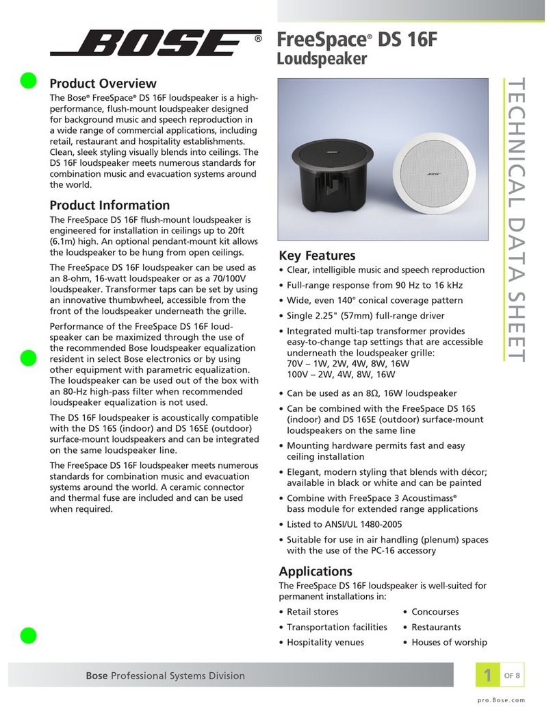
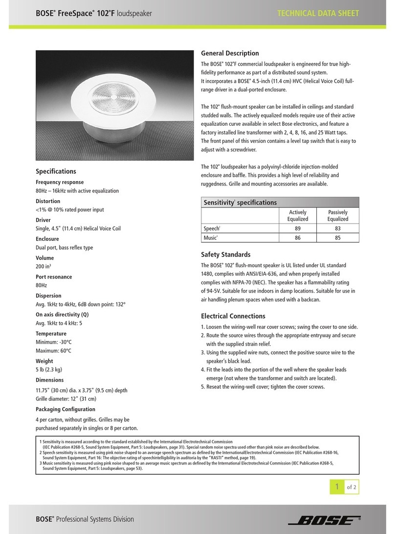
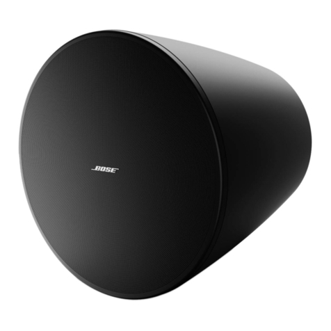
  9. Bose LT 3202 WR User manual

Bose LT 3202 WR User manual

©2010 Bose Corporation Reference Number 323102-SM Rev. 00
Service Manual
Panaray®LT Weather Resistant
Loudspeakers
Models 3202®WR, 4402®WR, 9402TM WR,
9702®WR, MB24 WR and MB12 WR
2
CONTENTS
CAUTION: The Bose®Panaray LT Weather Resistant (WR) Loudspeakers
contain no user-serviceable parts. To prevent warranty infractions,
refer servicing to warranty service stations or factory service.
WARRANTY INFORMATION
The Bose Panaray LT Model 3202, 4402, 9402, 9702, MB24 and MB12 Weather Resistant
Loudspeakers are covered by a 5-year transferable limited warranty.
PROPRIETARY INFORMATION
THISDOCUMENTCONTAINS PROPRIETARYINFORMATIONOF
BOSE CORPORATION WHICH IS BEING FURNISHED ONLY FOR
THE PURPOSE OF SERVICING THE IDENTIFIED BOSE PRODUCT
BYAN AUTHORIZED BOSE SERVICE CENTER OR OWNER OF
THE BOSE PRODUCT, AND SHALL NOT BE REPRODUCED OR
USED FOR ANY OTHER PURPOSE.
Warranty Information ......................................................................................................................................2
Specifications ............................................................................................................................................... 3-4
ProductDescription .........................................................................................................................................5
Part List Notes ..................................................................................................................................................5
Packing List, Panaray®LT 3202®WR Loudspeaker ......................................................................................6
Figure 1. Panaray LT 3202 WR Loudspeaker Packaging View ........................................................6
Packing List, Panaray LT 4402®WR Loudspeaker ........................................................................................7
Figure 2. Panaray LT 4402 WR Loudspeaker Packaging View ........................................................7
Packing List, Panaray LT 9402TM WR Loudspeaker .......................................................................8
Figure 3. Panaray LT 9402 WR Loudspeaker Packaging View .......................................................8
Packing List, Panaray LT 9702®WR Loudspeaker ........................................................................................9
Figure 4. Panaray LT 9702 WR Loudspeaker Packaging View ........................................................9
Packing List, Panaray LT MB24 WR Bass Loudspeaker ............................................................................. 10
Figure 5. Panaray LT MB24 WR Bass Loudspeaker Packaging View............................................10
Packing List, Panaray LT MB12 WR Bass Loudspeaker ............................................................................. 11
Figure 6. Panaray LT MB12 WR Bass Loudspeaker Packaging View............................................11
Main Part List, Panaray LT 3202 WR Loudspeaker (see Figure 7)............................................................. 12
Figure 7. Panaray LT 3202 WR Loudspeaker Exploded View ........................................................12
Main Part List, Panaray LT 4402 WR Loudspeaker (see Figure 8)............................................................. 13
Figure 8. Panaray LT 4402 WR Loudspeaker Exploded View ........................................................13
Main Part List, Panaray LT 9402 WR Loudspeaker (see Figure 9)............................................................. 14
Figure 9. Panaray LT 9402 WR Loudspeaker Exploded View ........................................................14
Main Part List, Panaray LT 9702 WR Loudspeaker (see Figure 10) ........................................................... 15
Figure 10. Panaray LT 9702 WR Loudspeaker Exploded View ......................................................15
Main Part List, Panaray LT MB24 WR Bass Loudspeaker .......................................................................... 16
Figure 11. Panaray LT MB24 WR Bass Loudspeaker Exploded View ............................................16
Main Part List, Panaray LT MB12 WR Bass Loudspeaker .......................................................................... 17
Figure 12. Panaray LT MB12 WR Bass Loudspeaker Exploded View............................................17
DisassemblyProcedures .......................................................................................................................... 18-20
Test Procedures ........................................................................................................................................ 21-22
Loudspeaker Wiring Diagrams................................................................................................................ 23-24
Accessories Used With the Panaray LT Series WR Loudspeakers ............................................................ 24
High Frequency Compression Driver Diaphragm Replacement Procedure ............................................. 25
Service Manual Revision History ................................................................................................................. 26
3
SPECIFICATIONS
MECHANICAL
External dimensions, single speaker
9702®WR: 42.2" H x 22.5" W x 18.0" D (1072 x 572 x 368 mm)
9402TM WR: 34.6" H x 22.5" W x 23.7" D (879 x 572 x 604 mm)
4402®WR: 34.0" H x 18.5" W x 24.0" D (884 x 471 x 610 mm)
3202®WR: 42.2" H x 22.5" W x 35.9" D (1072 x 573 x 913 mm)
MB24 WR: 28.1" H x 20.0" W x 25.5" D (712 x 508 x 647 mm)
MB12 WR: 14.5" H x 20.0" W x 25.5" D (368x 508 x 647 mm)
System weight, unpackaged single speaker
9702 WR: 95.5 lbs (43 kg)
9402 WR: 113.0 lbs (51 kg)
4402 WR: 111.1 lbs (50 kg)
3202 WR: 194.0 lbs (88 kg)
MB24 WR: 129.0 lbs (59 kg)
MB12 WR: 65.0 lbs (29.5 kg)
System weight, packaged single speaker
9702 WR: 123.5 lbs (56 kg)
9402 WR: 145.5 lbs (66 kg)
4402 WR: 141.1 lbs (64 kg)
3202 WR: 240.7 lbs (109 kg)
MB24 WR: 147.0 lbs (67 kg)
MB12 WR: 74 lbs (34 kg)
ELECTRICAL
Driver Complement
9702 WR: Mid Freq: two V2 drivers
High Freq: one 1.4" compression driver
9402 WR: Mid Freq: two V2 drivers
High Freq: one 1.4" compression driver
4402 WR: Mid Freq: two V2 drivers
High Freq: one 1.4" compression driver
3202 WR: Mid Freq: four V2 drivers
High Freq: one 1.4" compression driver
MB24 WR: Two 12" low frequency drivers
MB12 WR: One 12" low frequency driver
Sensitivity (dB SPL, 1Watt at 1 meter)
9702 WR: Mid 105, High 104, Passive 104
9402 WR: Mid 106, High 106, Passive 106
4402 WR: Mid 106, High 107, Passive 108
3202 WR: Mid 111, High 107, Passive 110
MB24 WR: Parallel Mode 94, Discrete Mode 91 (per driver)
MB12 WR: Discrete Mode 91
4
SPECIFICATIONS
ELECTRICAL (Continued)
Maximum sound pressure level (dB SPL) - pink noise per IEC 268-5
9702®WR: Mid 127, High 123, Passive 126
9402TM WR: Mid 128, High 125, Passive 128
4402®WR: Mid 126, High 128, Passive 130
3202®WR: Mid 132, High 130, Passive 135
MB24 WR: Parallel Mode 123, Discrete Mode 123
MB12 WR: Discrete Mode 117
Frequency Range
9702 WR: 180Hz - 16kHz (+ 3dB)
9402 WR: 180Hz - 16kHz (+ 3dB)
4402 WR: 180Hz - 16kHz (+ 3dB)
3202 WR: 200Hz - 16kHz (+ 3dB)
MB24 WR: 40Hz - 250Hz (+ 3dB)
MB12 WR: 40Hz - 250Hz (+ 3dB)
Loudspeaker Impedance
Compression Driver: 8 Ohms
Vee-Two: 2 Vee-Two's are wired in series for 8 Ohms
MB24 WR Bass Drivers: 8 Ohms each
MB12 WR Bass Driver: 8 Ohms
Maximum Power Handling, Watts
9702 WR: Bi-amped: Mid 140, High 75 Passive: 140
9402 WR: Bi-amped: Mid 140, High 75 Passive: 140
4402 WR: Bi-amped: Mid 140, High 75 Passive: 140
3202 WR: Bi-amped: Mid 280, High 75 Passive: 280
Bi-amped / Dual Midrange: Mid1 140; Mid2 140; High 75
MB24 WR: Parallel Mode 800, Discrete Mode 400 each driver
MB12 WR: Discrete Mode 400
5
PRODUCT DESCRIPTION
The Bose®Panaray®LT Weather Resistant (WR) Loudspeakers are designed to provide quality
sound in venues where speaker-to-listener distance, room reverberation time, ambient noise and
high SPL requirements are key factors. Typical installations include performing arts facilities,
theaters, auditoriums, houses of worship, stadiums and arenas.
The Panaray LT WR loudspeakers are a direct replacement for the Panaray LT Series III loud-
speaker. They are designed to be used in both indoor and under cover or outdoor environments.
The Panaray LT WR loudspeaker does not meet the requirements for permanent outdoor instal-
lation.
The Panaray LT WR loudspeakers utilize a high frequency compression driver and two or more
V2 assemblies for midrange. The MB24 bass module contains two 12 inch bass drivers. The
MB12 bass module contains one 12 bass driver.
The Panaray LT WR loudspeakers come standard with a perforated metal grille and are avail-
able in both black and white versions.
PART LIST NOTES
1. This part is not normally available from Customer Service.Approval from the Field Service
Manager is required before ordering.
2. The individual parts located on the PCBs are listed in the Electrical Part List.
3. This part is critical for safety purposes. Failure to use a substitute replacement with the
same safety characteristics as the recommended replacement part might create shock, fire
and/or other hazards.
4. This part is referenced for informational purposes only. It is not stocked as a repair part.
Refer to the next higher assembly for a replacement part.
6
PACKING LIST
Panaray®LT 3202®WR Loudspeaker
Figure 1. Panaray LT 3202 WR Loudspeaker Packaging View
Item
Number Description Bose
®
Part
Number
V
endor Part
Number Qty Note
1 PALLET
(
SINGLE USE
)
- B-TP-05 1 4
2 CARTON, LT3202-WR 322846-001S B-ZXW-5MG49 1 4
3 PAPER COVER 322842-001S B-ZZMW-5MG28 2 4
4 PP FOAM - B-ZZ-03 2 4
5 TRIANGLE PAPER 322843-001S B-ZBW-5MG06 2 4
6 PP FOAM, MIDDLE 322844-001S B-ZZM-04 1 4
7 SPEAKER CABINET REF - 1 4
8 PE BAG, 1850x1430x0.04mm 323115-001S B-BZD-11 1 4
9 TRIANGLE PAPER 322845-001S B-ZBW-5MG07 2 4
10 PE BAG, 310x220x0.04MM - 1-BZD-12 1 4
11 OWNER’S GUIDE 323176-001S - 1 4
7
PACKING LIST
Panaray®LT 4402®WR Loudspeaker
Figure 2. Panaray LT 4402 WR Loudspeaker Packaging View
Item
Number Description Bose
®
Part
Number
V
endor Part
Number Qty Note
1 PALLET
(
SINGLE USE
)
- B-TP-04 1 4
2 CARTON, LT4402-WR 322852-001S B-ZXW-5MG53 1 4
3 PAPER COVER, LT4402 322847-001S B2-ZZMW-5MG26 2 4
4 PP FOAM - B2-ZZMW-5MG23 2 4
5 TRIANGLE PAPER, LT4402 322851-001S B-ZBW-5MG25 2 4
6 PP FOAM, MIDDLE 322850-001S B-ZZM-08 1 4
7 SPEAKER CABINET REF - 1 4
8 PE BAG, 1600x1130x0.04mm 323116-001S B-BZD-08 1 4
9 TRIANGLE PAPER 322848-001S B-ZBW-5MG26 2 4
10 PE BAG, 310x220x0.04MM - 1-BZD-12 1 4
11 OWNER’S GUIDE 323176-001S - 1 4
8
PACKING LIST
Panaray®LT 9402TM WR Loudspeaker
Figure 3. Panaray LT 9402 WR Loudspeaker Packaging View
Item
Number Description Bose
®
Part
Number
V
endor Part
Number Qty Note
1 PALLET
(
SINGLE USE
)
- B-TP-03 1 4
2 CARTON, LT9402-WR 322856-001S B-ZXW-5MG54 1 4
3 PAPER COVER, LT9402 322853-001S B2-ZZMW-5MG27 2 4
4 PP FOAM - B2-ZZMW-5MG24 2 4
5 TRIANGLE PAPER, LT9402 322854-001S B-ZBW-5MG02 2 4
6 PP FOAM, MIDDLE 322855-001S B-ZZM-10 1 4
7 SPEAKER CABINET REF - 1 4
8 PE BAG, 1600x1130x0.04mm 323117-001S B-BZD-03 1 4
9 TRIANGLE PAPER 322854-001S B-ZBW-5MG02 2 4
10 PE BAG, 310x220x0.04MM - 1-BZD-12 1 4
11 OWNER’S GUIDE 323176-001S - 1 4
9
PACKING LIST
Panaray®LT 9702®WR Loudspeaker
Figure 4. Panaray LT 9702 WR Loudspeaker Packaging View
Item
Number Description Bose
®
Part
Number
V
endor Part
Number Qty Note
1 PALLET
(
SINGLE USE
)
- B-T
P
-09 1 4
2 CARTON, LT9702-WR 323089-001S B-ZXW-5MG46 1 4
3 PAPER COVER, LT9702 322857-001S B2-ZZMW-5MG29 2 4
4 PP FOAM - B2-ZZMW-5MG21 2 4
5 TRIANGLE PAPER, LT9702 322858-001S B-ZBW-5MG22 4 4
6 PP FOAM, MIDDLE 323088-001S B2-ZZMW-5MG22 1 4
7 SPEAKER CABINET REF - 1 4
8 PE BAG, 1500x900x0.04mm 323118-001S B-BZD-12 1 4
9 PE BAG, 310x220x0.04MM - 1-BZD-12 1 4
10 OWNER’S GUIDE 323176-001S - 1 4
10
PACKING LIST
Panaray®LT MB24 WR Bass Loudspeaker
Figure 5. Panaray LT MB24 WR Bass Loudspeaker Packaging View
Item
Number Description Bose
®
Part
Number
V
endor Part
Number Qty Note
1 PALLET
(
SINGLE USE
)
- B-T
P
-01 1 4
2 CARTON, MB24-WR 323095-001S B-ZXW-5MG50 1 4
3 PAPER COVER, MB24 323093-001S B2-ZZMW-5MG31 2 4
4 PP FOAM 323090-001S B-ZZM-01 2 4
5 TRIANGLE PAPER, MB24 323094-001S B-ZBW-5MG01 4 4
6 SPEAKER CABINET REF - 1 4
7 PP FOAM, MIDDLE 323092-001S B-ZZM-02 1 4
8 PE BAG, 1600x1160x0.01MM 323119-001S B-BZD-05 1 4
9 PE BAG, 310x220x0.04MM - 1-BZD-12 1 4
10 OWNER’S GUIDE 323177-001S - 1 4
11
PACKING LIST
Panaray®LT MB12 WR Bass Loudspeaker
Figure 6. Panaray LT MB12 WR Bass Loudspeaker Packaging View
Item
Number Description Bose
®
Part
Number
V
endor Part
Number Qty Note
1 PALLET
(
SINGLE USE
)
- B-TP-07 1 4
2 CARTON, MB12-WR 323098-001S B-ZXW-5MG51 1 4
3 PAPER COVER, MB12 323096-001S B2-ZZMW-5MG30 2 4
4 PP FOAM 323097-001S B-ZZM-17 2 4
5 SPEAKER CABINET REF - 1 4
6 PE BAG, 1260x1200x0.04MM 323120-001S 4-BZD-45 1 4
7 PE BAG, 310x220x0.04MM - 1-BZD-12 1 4
8 OWNER’S GUIDE 323177-001S - 1 4
12
Figure 7. Panaray LT 3202 WR Loudspeaker Exploded View
123 456789
10
11
12131415161718192021
22
MAIN PART LIST
Panaray®LT 3202®WR Loudspeaker (see Figure 7)
Item
Number Description
V
endor Part
Number Qt
y
Note
1 Kit, Grille Screw, TA4x15 (14 screws per kit)
Black
White
297502
297503
1
2 Washer, Flat, 4x9x0.8mm - 10 4
3 Grille Assy (with screws & logo assy.)
Black
White
322818-010S
298556
1
4 Gasket, Grille, consists of 3 sections 274622 1
5 Gasket, EVA, V2 Cover, 594.3x290x1mm, Blk - 2 4
6 V2 Cover, Blk 322823-010S 1
7 Screw, V2 Cover, Blk - 2 4
8 Gasket, Rubber, 525x19x1mm, Blk - 2 4
9 VEE-Two Assembly (includes drivers), Blk 298172 4
10 Screw, VEE-Two Assy. - 16 4
11 Washer, N
y
lon, 12x6.6x1mm, Blk - 1
6
4
12 Screw, InputPanel,TM4x15 - 12 4
13 Input Panel with Crossover PCB, Black 322698-010S 1
14 Gasket, Input Panel 298558 1
15 Crossover PCB Assembly - 1 4
16 Gasket, EVA, 138x68x2mm - 1 4
1
7
Screw, 6x30mm, Stainless, Blk - 4 4
18 Compression Driver Assy, 1.4” 276860 1
19 Disk, Alignment, Compression Driver 263912 1
2
0
Gasket, Com
p
ression Drive
r
263911 1
21 - Insert, Rigging,3/8x16 thread
- Screw,9.5x20mm, Stainless,Blk
- Washer,PVC,15.5x9.6x0.4mm
-
-
-
16
16
32
4
22 Logo Kitwith tape, fastener and spring
Black
White
297504
297505
1
- Compression Driver Replacement Diaphragm 276861 1
- Screw, Han
g
Point, 3/8” x 16 298591 1
6
13
MAIN PART LIST
Panaray®LT 4402®WR Loudspeaker (see Figure 8)
Figure 8. Panaray LT 4402 WR Loudspeaker Exploded View
12 3456789
10
111213141516171819
20
Item
Number Description Bose
®
Part
Number Qty Note
1 Kit, Grille Screw, TA4x15 (14 screws per kit)
Black
White
297502
297503
1
2 Washer, Flat, 4x9x0.8mm - 10 4
3 Grille Assembly with screws, tape, logo
Black
White
322819-010S
298580
1
4 Gasket, EVA, V2 Cover, 351x290x1mm, Black - 1 4
5 V2 Cover 322820-010S 1
6 Gasket, Rubber, 262x19x1,Black - 2 4
7 Screw, V2 Cover, H/H6x30mm,D=10, Black - 2 4
8 V2 Assembl
y
(
includes drivers
)
, Black 298172 2
9 Washer, V2 Assy, Nylon, 12x6.6x1mm, Black - 8 4
10 Screw, V2 Assy,13x6x90mm, Black - 8 4
11 Screw, In
p
utPanel - 1
2
4
12 Input Panel Assembly (with crossover PCB) 322821-010S 1
13 Gasket, EVA, Input Panel 298558 1
14 Screw, Compression Driver, TM6x30 - 4 4
15 Compression Driver 276860 1
16 Disk, Alignment, Compression Driver 263912 1
17 Gasket, EVA, Com
p
ression Drive
r
263911 1
18 - Insert, Rigging,3/8x16 thread
- Screw, 9.5x20mm, Stainless, Blk
- Washer,PVC,15.5x9.6x0.4mm
-
-
-
16
16
32
4
19 Gasket, Grille, consists of 3 sections 274622 1
20 Logo Kitwith tape, fastener and spring
Black
White
297504
297505
1
- Compression Driver Replacement Diaphragm 276861 1
- Screw, Hang Point, 3/8” x 16 298591 16
14
MAIN PART LIST
Panaray®LT 9402TM WR Loudspeaker (see Figure 9)
12 345 6 789
10
1112131415
161718
19
20
Figure 9. Panaray LT 9402 WR Loudspeaker Exploded View
Item
Number Description Bose
®
Part
Number Qty Note
1 Kit, Grille Screw, TA4x15 (14 screws per kit)
Black
White
297502
297503
1
2 Washer, Flat, 4x9x0.8mm - 10 4
3 Grille Assy (with screws & logo assy.)
Black
White
322822-010S
298584
1
4 EVA Gasket, V2 Cover - 1
5 V2 Cover 322820-010S 1
6 Gasket, Rubber, 262x19x1,Blk - 2
7 Screw, V2 Cover, 6x30M, D=10, Stainless, Blk - 2
8 V2 Assembl
y
298172 2
9 Washer, Nylon, 12x6.6x1mm, Blk - 8
10 Screw, VEE-Two Assy. - 8
11 Screw, In
p
utPanel,TM4x15 - 1
2
12 Input Panel with Crossover PCB, Black 322824-010S 1
13 Gasket, Input Panel - 1
14 Screw, Compression Driver, 6x30mm,SS, Blk - 4
15 Compression Driver Assy 276860 1
16 Disk, Alignment, Compression Driver 263912 1
17 Gasket, Com
p
ression Drive
r
263911 1
18 - Insert, Rigging,3/8x16 thread
- Screw, 9.5x20mm, Stainless, Blk
- Washer,PVC,15.5x9.6x0.4mm
-
-
-
16
16
32
4
19 Gasket, grille
20 Logo Kitwith tape, fastener and spring
Black
White
297504
297505
1
- Compression Driver Replacement Diaphragm 276861 1
- Screw, Hang Point, 3/8” x 16 298591 16
15
MAIN PART LIST
Panaray®LT 9702®WR Loudspeaker (see Figure 10)
Figure 10. Panaray LT 9702 WR Loudspeaker Exploded View
123 45 678910
111213141516171819
20
Item
Number Description Bose
®
Part
Number Qty Note
1 Kit, Grille Screw, TA4x15 (14 screws per kit)
Black
White
297502
297503
1
2 Washer, Flat, 4x9x0.8mm - 10 4
3 Grille Assy (with screws & logo assy.)
Black
White
322825-010S
298586
1
4 EVA Gasket, V2 Cover - 1
5 V2 Cover 322820-010S 1
6 Gasket, Rubber, 262x19x1,Blk - 2
7 Screw, V2 Cover, 6x30M, D=10, Stainless, Blk - 2
8 V2 Assembl
y
298172 2
9 Washer, Nylon, 12x6.6x1mm, Blk - 8
10 Screw, VEE-Two Assy. - 8
11 Screw, In
p
utPanel,TM4x15 - 1
2
12 Input Panel with Crossover PCB, Black 322827-010S 1
13 Gasket, Input Panel - 1
14 Screw, Compression Driver, 6x30mm,SS, Blk - 4
15 Compression Driver Assy 276860 1
16 Disk, Alignment, Compression Driver 263912 1
17 Gasket, Com
p
ression Drive
r
263911 1
18 - Insert, Rigging,3/8x16 thread
- Screw, 9.5x20mm, Stainless, Blk
- Washer,PVC,15.5x9.6x0.4mm
-
-
-
16
16
32
4
19 Gasket, grille
20 Logo Kitwith tape, fastener and spring
Black
White
297504
297505
1
- Compression Driver Replacement Diaphragm 276861 1
- Screw, Hang Point, 3/8” x 16 298591 16
16
MAIN PART LIST
Panaray®LT MB24 WR Bass Loudspeaker
Figure 11. Panaray LT MB24 WR Bass Loudspeaker Exploded View
123 4 567
8
9
10
11
12
Item
Number Description Bose
®
Part
Number Qty Note
1 Grille Screw Kit (14 screws)
Black
White
297502
291904
2 Washer, Flat, Grille, 4x9x0.8mm - 10
3 Grille Assembly, includes screws, logo, tape,
fastener and spring
Black
White
322828-010S
298561
1
4 Gasket, EVA, Grille - 4
5 Screw, Woofer - 16 4
6 Woofer Assy, 12 inch, TBX 297519 2
7 Gasket, EVA, Woofer - 2
8 Screw, In
p
ut Panel - 8 4
9 Input Panel Assy with Crossover PCB, Blk 322829-010S 1
10 Gasket, EVA, Input Panel - 1 4
11 - Insert, Rigging,3/8x16 thread
- Screw, 9.5x20mm, Stainless, Blk
- Washer,PVC,15.5x9.6x0.4mm
-
-
-
16
16
32
4
12 Logo Kit, includes tape, fastener and spring
Black
White
276848
297505
1
- Screw, Hang Point, 3/8” x 16 298591 16
17
MAIN PART LIST
Panaray®LT MB12 WR Bass Loudspeaker
Figure 12. Panaray LT MB12 WR Bass Loudspeaker Exploded View
123 4567
8
9
10
11
12
Item
Number Description Bose
®
Part
Number Qt
y
Note
1 Grille Screw Kit (14 screws)
Black
White
297502
297503
2 Washer, Flat, Grille, 4x9x0.8mm - 10
3 Grille Assembly, includes screws, logo, tape,
fastener and spring
Black
White
323099-010S
298588
1
4 Gasket, EVA, Grille - 4
5 Screw, Woofer - 8 4
6 Woofer Assy, 12 inch, TBX 297519 1
7 Gasket, EVA, Woofe
r
- 1
8 Screw, Input Panel - 8 4
9 Input Panel Assy with Crossover PCB, Blk 323100-010S 1
10 Gasket, EVA, Input Panel - 1 4
11 - Insert, Rigging, 3/8x16 thread
- Screw, 9.5x20mm, Stainless, Blk
- Washer, PVC, 15.5x9.6x0.4mm
-
-
-
16
16
32
4
12 Logo Kit, includes tape, fastener and spring
Black
White
297504
297505
1
- Screw, Hang Point, 3/8” x 16 298591 16
18
DISASSEMBLY PROCEDURES
CAUTION: The rear of the Panaray®LT
loudspeakers can become extremely hot
during normal use. Do not attempt to service
the loudspeakers until they have cooled to
room temperature.
Model 3202®WR Loudspeaker
Note: Refer to Figure 7 for the following
procedures.
1. Grille Removal
1.1 Remove the fourteen screws (1) that
secure the grille assembly (3) to the cabinet.
1.2 Lift the grille assembly off of the cabinet.
The gasket should remain adhered to the
cabinet.
2. Logo Removal
2.1 Remove the grille using procedure 1
above.
2.2 On the back of the grille, carefully re-
move the slotted washer that retains the
spring and spacer against the back of the
grille. Note the direction the spacer faces.
Slide the spring and spacer off of the logo
post.
3. Input Panel Assembly Removal
3.1 Remove the twelve screws (12) that
secure the input panel assembly (13) to the
cabinet. Disconnect the cables that plug into
the PCB. Lift out the assembly.
4. Compression Driver Removal
4.1 Remove the twelve screws (12) that
secure the input panel (13) to the cabinet. Lift
off the input panel. Retain the gasket (14) for
re-use.
4.2 Remove the four screws (17) that secure
the Compression Driver (18) to the cabinet.
Lift the compression driver out of the cabinet.
Make a note of the wiring configuration, and
disconnect the wires from the compression
driver.
4.3 Remove the four screws that secure the
compression driver to the mounting plate. Lift
off the driver.
5. V2 Two Assembly Removal
5.1 Remove the four screws (10) that secure
the V2 assembly (9) to the cabinet. These
screws are located at the four corners of the
assembly. Do not remove the other screws
around the casting. Carefully lift the assem-
bly out of the cabinet. Make a note of the
wiring configuration, and disconnect the two
wires from the connector.
Model 4402®WR Loudspeaker
Note: Refer to Figure 8 for the following
procedures.
1. Grille Removal
1.1 Remove the fourteen screws (1) that
secure the sides of the grille assembly (3) to
the cabinet.
1.2 Lift the grille assembly off of the cabinet.
The gasket should remain adhered to the
cabinet.
2. Logo Removal
2.1 Remove the grille using procedure 1
above.
2.2 On the back of the grille, carefully re-
move the slotted washer that retains the
spring and spacer against the back of the
grille. Note the direction the spacer faces.
Slide the spring and spacer off of the logo
post.
2.3 Lift the logo off of the grille.
19
DISASSEMBLY PROCEDURES
3. Input Panel Assembly Removal
3.1 Remove the twelve screws (11) that
secure the input panel assembly (12) to the
cabinet. Lift the assembly away from the
cabinet. Disconnect the cables that plug into
the PCB. Lift out the assembly.
4. Compression Driver Removal
4.1 Remove the twelve screws (11) that
secure the input panel (12) to the cabinet. Lift
off the rear panel. The gasket should remain
adhered to the cabinet.
4.2 Make a note of the wiring configuration,
and disconnect the wires from the compres-
sion driver. Remove the four screws (14) that
secure the Compression Driver (15) to the
cabinet. Lift the compression driver out of the
cabinet.
5. V2 Two Assembly Removal
5.1 Remove the four screws (10) that secure
the V2 assembly (8) to the cabinet. These
screws are located at the four corners of the
assembly. Do not remove the other screws
around the casting. Carefully lift the assem-
bly out of the cabinet. Make a note of the
wiring configuration, and disconnect the two
wires from the connector.
Model 9402TM WR Loudspeaker
Note: Refer to Figure 9 for the following
procedures.
1. Grille Removal
1.1 Remove the fourteen screws (1) that
secure the grille assembly (3) to the cabinet.
1.2 Lift the grille assembly off of the cabinet.
The gasket should remain adhered to the
cabinet.
2. Logo Removal
2.1 Remove the grille using procedure 1
above.
2.2 On the back of the grille, carefully re-
move the slotted washer that retains the
spring and spacer against the back of the
grille. Note the direction the spacer faces.
Slide the spring and spacer off of the logo
post.
2.3 Lift the logo off of the grille.
3. Input Panel Assembly Removal
3.1 Remove the twelve screws (11) that
secure the input panel assembly to the
cabinet. Lift the assembly away from the
cabinet. Disconnect the cables that plug into
the PCB. Lift out the assembly.
4. Compression Driver Removal
4.1 Remove the twelve screws (11) that
secure the input panel (12) to the cabinet.
Lift off the rear panel. The gasket should
remain adhered to the cabinet.
4.2 Make a note of the wiring configuration,
and disconnect the wires from the compres-
sion driver. Remove the four screws (14)
that secure the Compression Driver (15) to
the cabinet. Lift the compression driver out
of the cabinet.
5. V2 Two Assembly Removal
5.1 Remove the four screws (10) that
secure the V2 assembly (8) to the cabinet.
These screws are located at the four
corners of the assembly. Do not remove the
other screws around the casting. Carefully
lift the assembly out of the cabinet. Make a
note of the wiring configuration, and discon-
nect the two wires from the connector.
20
DISASSEMBLY PROCEDURES
Model 9702®WR Loudspeaker
Note: Refer to Figure 10 for the following
procedures.
1. Grille Removal
1.1 Remove the fourteen screws (1) that
secure the grille assembly (3) to the cabinet.
1.2 Lift the grille assembly off of the cabinet.
The gasket should remain adhered to the
cabinet.
2. Logo Removal
2.1 Remove the grille using procedure 1
above.
2.2 On the back of the grille, carefully re-
move the slotted washer that retains the
spring and spacer against the back of the
grille. Note the direction the spacer faces.
Slide the spring and spacer off of the logo
post.
2.3 Lift the logo off of the grille.
3. Input Panel Assembly Removal
3.1 Remove the twelve screws (11) that
secure the input panel assembly (12) to the
cabinet. Disconnect the cables that plug into
the PCB. Lift out the assembly.
4. Compression Driver Removal
4.1 Remove the twelve screws (11) that
secure the input panel (12) to the cabinet.
Lift off the rear panel. The gasket should
remain adhered to the cabinet.
4.2 Make a note of the wiring configuration,
and disconnect the wires from the compres-
sion driver. Remove the four screws (14)
that secure the Compression Driver (15) to
the cabinet. Lift the compression driver out
of the cabinet.
5. V2 Two Assembly Removal
5.1 Remove the four screws (10) that
secure the V2 assembly (8) to the cabinet.
These screws are located at the four
corners of the assembly. Do not remove the
other screws around the casting. Carefully
lift the assembly out of the cabinet. Make a
note of the wiring configuration, and discon-
nect the two wires from the connector.
V2 Two Driver Removal Procedure
1. Remove the V2 Two assembly using the
appropriate disassembly procedures for the
speaker under repair.
2. Place the VEE Two assembly on a flat
surface so that the aluminum casting with
the Bose logo is facing upward.
3. Using a Phillips-head screwdriver, remove
all of the screws around the perimeter of the
casting. Carefully lift off the casting. The
drivers will be exposed.
4. Make a note of the wiring configuration,
and cut the wires as close to the terminals
as possible.
5. Remove the three screws that secure the
driver into the housing. Lift it out of the
housing.
Re-assembly note: When installing the
new driver, ensure that the gasket for the
driver and the gasket for the aluminum
casting are correctly positioned to provide
an airtight seal after re-assembly.
Model MB24 and MB12 WR Bass Loud-
speakers
Refer to Figure 11 or 12, as appropriate,
for the following procedures.
1. Grille Removal
1.1 Using a Phillips-head screwdriver, re-
move the screws (1) that secure the grille
(3) to the enclosure. Lift off the grille.

This manual suits for next models

5

Other Bose Speakers manuals

Bose SoundTouch20 Wi-Fi S User manual

Bose

Bose SoundTouch20 Wi-Fi S User manual

Bose Surround Speakers User manual

Bose

Bose Surround Speakers User manual

Bose 161 Quick start guide

Bose

Bose 161 Quick start guide

Bose FreeSpace FS2P User manual

Bose

Bose FreeSpace FS2P User manual

Bose Virtually Invisible 791 series II User manual

Bose

Bose Virtually Invisible 791 series II User manual

Bose 431974 User manual

Bose

Bose 431974 User manual

Bose SOUNDLINK MICRO User manual

Bose

Bose SOUNDLINK MICRO User manual

Bose SoundLink Bluetooth Mobile Speaker II User manual

Bose

Bose SoundLink Bluetooth Mobile Speaker II User manual

Bose HOME SPEAKER 500 User manual

Bose

Bose HOME SPEAKER 500 User manual

Bose SOUNDLINK REVOLVE II User manual

Bose

Bose SOUNDLINK REVOLVE II User manual

Bose SoundLink Bluetooth Mobile Speaker II User manual

Bose

Bose SoundLink Bluetooth Mobile Speaker II User manual

Bose DesignMax DM3SE User manual

Bose

Bose DesignMax DM3SE User manual

Bose 301 Series IV User manual

Bose

Bose 301 Series IV User manual

Bose SOUNDLINK MICRO Dimensions

Bose

Bose SOUNDLINK MICRO Dimensions

Bose SoundLink Mini Bluetooth Speaker User manual

Bose

Bose SoundLink Mini Bluetooth Speaker User manual

Bose SoundLink Mini Bluetooth speaker II User manual

Bose

Bose SoundLink Mini Bluetooth speaker II User manual

Bose EdgeMax EM90 User manual

Bose

Bose EdgeMax EM90 User manual

Bose SoundLink Bluetooth speaker III User manual

Bose

Bose SoundLink Bluetooth speaker III User manual

Bose Lifestyle PS 18 User manual

Bose

Bose Lifestyle PS 18 User manual

Bose 301 Series III User manual

Bose

Bose 301 Series III User manual

Bose Acoustimass-20 User manual

Bose

Bose Acoustimass-20 User manual

Bose SOUNDLINK FLEX User manual

Bose

Bose SOUNDLINK FLEX User manual

Bose Free Space 51 User manual

Bose

Bose Free Space 51 User manual

Bose 901 Quick start guide

Bose

Bose 901 Quick start guide

Popular Speakers manuals by other brands

TaoTronics TT-SK11 user guide

TaoTronics

TaoTronics TT-SK11 user guide

ELAC IW 1030 operating instructions

ELAC

ELAC IW 1030 operating instructions

WHD SOUNDWAVER manual

WHD

WHD SOUNDWAVER manual

Mackie DRM212 owner's manual

Mackie

Mackie DRM212 owner's manual

Kenwood KVS-200 Setting up

Kenwood

Kenwood KVS-200 Setting up

Clas Ohlson SP4080-UK manual

Clas Ohlson

Clas Ohlson SP4080-UK manual

PROEL FREEPACK 65 user manual

PROEL

PROEL FREEPACK 65 user manual

Steren MP3-850 instruction manual

Steren

Steren MP3-850 instruction manual

Anchor AN-30 Specification sheet

Anchor

Anchor AN-30 Specification sheet

LG PL7W owner's manual

LG

LG PL7W owner's manual

Beta Three Ra12 user manual

Beta Three

Beta Three Ra12 user manual

Philips S4405 user manual

Philips

Philips S4405 user manual

iDance ACDC CLASSIC 2 user manual

iDance

iDance ACDC CLASSIC 2 user manual

Bang & Olufsen Celestial BOC100 Series installation manual

Bang & Olufsen

Bang & Olufsen Celestial BOC100 Series installation manual

Adire Audio HE10.1 Assembly instructions

Adire Audio

Adire Audio HE10.1 Assembly instructions

2E 2E-PCS301BK user manual

2E

2E 2E-PCS301BK user manual

Nady Audio MaxTower PAS-250 owner's manual

Nady Audio

Nady Audio MaxTower PAS-250 owner's manual

EarFun UBOOM L user manual

EarFun

EarFun UBOOM L user manual

manuals.online logo
manuals.online logoBrands
  • About & Mission
  • Contact us
  • Privacy Policy
  • Terms and Conditions

Copyright 2025 Manuals.Online. All Rights Reserved.