BOSER Technology Transmeta Crusoe HS-1600 User manual

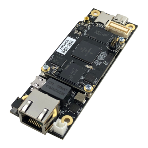
HS-1600
Transmeta Crusoe Mini Board
•Crusoe CPU•CRT/Panel•SODIMM•DiskOnChip•
•LAN•4COM•Mini PCI•IrDA•USB•Sound•Single +5V•
•Transmeta Embedded Industrial Single Board Computer•

Copyrights
Unauthorizedcopying,photocopying,translation,orreproduction of this manual to
any electronic or machine readable form in whole or in part without prior written
consent from the manufacturer is prohibited.
In general, the manufacturer will not be liable for any direct, indirect, special,
incidental or consequential damages arising from the use of inability to use the
product or documentation, even if advised of the possibility of such damages.
Themanufacturerreservestherightstochangethecontentsofthismanualwithout
prior notice in order to improve the function design, performance, quality and
reliability of the product. The author assumes no responsibility for any errors or
omissions, which may appear in this manual, nor does it make a commitment to
update the information contained herein.
Trademarks
BOSER is a registered trademark of BOSER Technology Co., Ltd.
ISB is a registered trademark of BOSER Technology Co., Ltd.
Intel is a registered trademark of Intel Corporation.
Award is a registered trademark of Award International Inc.
All other trademarks, products and or product's name mentioned herein are
mentioned for identification purposes only, and may be trademarks and/or
registered trademarks of their respective companies or owners.
© Copyright 2001
All Rights Reserved.
User’s Manual edition1.1,Aug.24 2001

Contents?i
Contents
HS-1600...................................................................................................................1
GENERAL INFORMATION.........................................................................................3
1.1 MAJOR FEATURES..................................................................................................4
1.2 SPECIFICATIONS ......................................................................................................5
1.3 DELIVERY PACKAGE..............................................................................................6
HARDWARE INSTALLATION...................................................................................7
2.1 CAUTION OF STATIC ELECTRICITY........................................................................7
2.2 CAUTION ON UNPACKING AND BEFORE INSTALLATION......................................8
2.3 HS-1600’S LAYOUT..............................................................................................9
2.4 QUICK LISTING OF JUMPERS AND CONNECTORS ...............................................10
2.5 JUMPER SETTING DESCRIPTION............................................................................11
2.6 CMOS CLEAN......................................................................................................12
2.7 SYSTEM MEMORY DRAM...................................................................................12
2.8 SETTING THE FLAT PANEL VOLTAGE.................................................................13
2.9 DISKONCHIP..........................................................................................................13
2.10 WATCH DOG TIMER............................................................................................13
CONNECTION..............................................................................................................14
3.1 POWER AND FAN CONNECTORS .......................................................................14
3.2 RESET BUTTON.....................................................................................................15
3.3 AUDIO SETTING.....................................................................................................15
3.4 PCI E-IDE DRIVE CONNECTOR..........................................................................16
3.5PARALLEL PORT CONNECTOR............................................................................17
3.6 THE FLOPPY DISK DRIVE CONNECTOR...............................................................18
3.7 SERIAL PORTS CONNECTORS.............................................................................19
3.8 KEYBOARD/MOUSE CONNECTORS.....................................................................21
3.9 VGA CRT AND LCD CONNECTORS..................................................................22
3.10 IR CONNECTOR...................................................................................................24
3.11 USB PORTS CONNECTOR................................................................................25
3.12 LAN INTERFACE CONNECTOR...........................................................................25
3.13 MINI PCI CONNECTOR.......................................................................................26

ii ?Contents
AWARD BIOS SETUP...............................................................................................28
4.1 MAIN MENU...........................................................................................................29
4.2 STANDARD CMOS SETUP..................................................................................30
4.3 ADVANCED BIOS FEATURES .............................................................................31
4.4 INTEGRATED PERIPHERALS..................................................................................32
4.5 POWER MANAGEMENT SETUP............................................................................34
4.6 PNP/PCI CONFIGURATION SETUP.....................................................................35
SOFTWARE UTILITIES............................................................................................36
5.1 VGA DRIVER INSTALL FOR WIN98...................................................................37
5.2 VGA DRIVER INSTALL FOR WIN NT4.0...........................................................39
5.3 NETWORK DRIVER INSTALL FOR WIN98...........................................................49
5.4 NETWORK DRIVER INSTALL FOR WIN NT4.0...................................................47
5.5 SOUND DRIVER INSTALL FOR WIN98................................................................55
5.6 SOUND DRIVER INSTALL FOR WIN NT4.0........................................................59

3
Chapter-1
General Information
The HS-1600 is a 66MHz Bus,Via VT86C686 chipset based Mini
Embedded SBC with combined features to make it an ideal all-in-one
industrial single board computer with enhanced I/O effects, LAN and VGA
interface.
With on board DMA33 IDE drive interface architecture, the HS-1600
supports a maximum of 33MB/sec data transfer rate with one IDE drive
connection. The 69000 CRT/Panel display controller provides a resolution
of up to 1280x1024, 256 colors. The SBC also provides one internal 40-pin
connector for use with various types of the LCD Panel connection.
The HS-1600 providesone SODIMM socket that supports up to256MB of
mainsystemmemory. AsingleFlash chip holds the system BIOS, and you
can easily update the Flash BIOS by the Utility Update software. Advanced
USB and IrDA ports are also provided for faster and convenient data
transmission.
The HS-1600 also features one Realtek RTL8139 100 Based Ethernet
controller and the ESS Solo1 3D Sound chip on board.

4
1.1 Major Features
?? Transmeta Crusoe TM3200 400MHz or TM5400 600MHz CPU
?? Via VT82C686A Chipset
?? One SODIMM socket supports up to 256MB
?? Mini PCI Local Bus support
?? Three RS-232 and one RS-232/422/485 serial ports include 16C550
UART with 16byte FIFO
?? One enhanced bi-directional parallel port support SPP/ECP/EPP
?? On board two USB ports and one IrDA port
?? On board SMC 37C669
?? On board 69000 CRT/Panel display controller
?? On board Realtek RTL8139 100 Based LAN
?? On board ESS Solo1 3D Sound
?? Single +5V support
?? Provides socket for DiskOnChipTM
?? Watchdog Timer Function support
?? On board PS/2 Keyboard/Mouse connector

5
1.2 Specifications
??CPU: Transmeta Crusoe TM3200 400MHz / TM5400 600MHz CPU
??Bus Interface: Mini PCI Local Bus
??Memory: One SODIMM socket provides up to 256MB
??Chipset: Via VT82C686
??Data Bus: 64bit
??VGA: 69000 with 2MB memory support CRT/Panel display up to
1280x1024x256 colors
??IDE: Two IDE disk drives support DMA33 transfer rate up to 33MB/sec
??Floppy: Support up to one floppy disk drives
??Parallel Port: Support SPP/ECP/EPP
??LAN: Realtek RTL8139C 100 Based LAN
??Sound: ESS Solo1 3D Sound
??Serial Port: Three RS-232 and one RS-232/422/485 serial ports
include 16C550 UART with 16byte FIFO
??IR: One IrDA TX/RX header
??USB: Support two USB ports
??Keyboard/Mouse: 6-pin SMD type connector
??DiskOnChip: Socket for DiskOnChip and memory size up to 144MB
??BIOS: Award Y2K PnP Flash BIOS
??DMA Channels: 7
??Interrupt: 15
??Main Power: Single +5V Power In
??Maximum Power Consumption: [email protected] (TM3200 400MHz)

6
??Operating Temperature: 0~60℃
??Board Size: 11.25x10.2 cm
1.3 Delivery Package
The delivery package of HS-1600 includes the following items:
?? One HS-1600 Industrial Single Board
?? One Printer Ports Flat Cable
?? One COM port Flat Cable
?? One IDE port Flat Cable
?? One FDD port Flat Cable
?? One PS/2 Keyboard/Mouse Transfer Cable
?? One Panel connector Flat Cable
?? One 2-pin Power Transfer Cable
?? One RJ45 Transfer Cable
?? One Audio Port Transfer Cable
?? One 15-pin VGA Transfer Cable
?? Utility Diskette
?? User’s Manual
Please contact your dealer if any of the items are missing or
damaged. Please store all parts of the delivery package with packing
materials in case you want to ship or store the product in the future.

7
Chapter-2
Hardware Installation
This chapter provides the information on how to install the hardware of
HS-1600. First, proceed with sections 1.3, 2.1 and 2.2 to check the
delivery package and for unpacking. Afterwards, go to the jumpers
setting section.
2.1 Caution of Static Electricity
The HS-1600 has been well packaged with an anti-static bag to
protect the sensitive computer components and circuitry from the
damage of static electric discharge.
Note: DO NOT TOUCH THE BOARD OR ANY OTHER SENSITIVE
COMPONENTS WITHOUT ALL NECESSARY ANTI-STATIC
PROTECTION.
You should follow the steps below to protect the board in against
static electric discharge whenever you handle the board:
1. Use a grounding wrist strap to handle the HS-1600. Well clip the
ALLIGATOR clip of the strap to the end of the shielded wire lead
from a grounded object. Put on and connect the strap before
handling the HS-1600 to harmlessly discharge any static electricity
through the strap.
2. Use an anti-static pad to put any components or parts or tools on
the pad whenever you work on them outside the computer. You may
also use the anti-static bag instead the pad. Please ask your local
supplier to help up get the any anti-static requirement that you may
need.

8
2.2 Caution on Unpacking and Before Installation
First, proceed with the steps in section 2.1 to protect the HS-1600
from electricity discharge. Refer to section 1.3 in checking the delivery
package again with the following steps:
1.Unpack the HS-1600, store all packing material, manual and any
diskette.
2.Is there any component missing or loosen from the board? DO NOT
INSTALL IF THIS HAPPENS.
3.Is there any visual damage on the board? DO NOT INSTALL IF THIS
HAPPENS.
4.Carefully check the optional parts (i.e. CPU, SRAM, DRAM,
ROM-Disk etc.) and complete setting all necessary jumpers,
jumper pin-set and CMOS setup correctly. Please also refer to all
information on jumpers setting in this manual.
5.Carefully check all external devices (i.e. Add-On-Card, Driver Type
etc.) to complete the add-in or connection and CMOS setup
correctly. Please also refer to all information on the connector
connections in this manual.
6.Please keep all necessary manual and diskette in a good condition
for your necessary re-installation if you change your Operating
System or whatever needs.

9
2.3 HS-1600’s Layout

10
2.4 Quick Listing of Jumpers and Connectors
PC1 ?Mini PCI Slot ?P.26
J1 ?Reset ?P.15
J2 ?TDM Debug connector
JP1 ?Panel Voltage select ?P.12
JP2 ?COM2 RS-232/422/485 select ?P.19
JP3?AUX In connector ?P.15
JP4?COM2 Enabled/Disable select ?P.19
JP5 ?AUX In ?P.15
JP6 ?Audio Out ?P.15
CN1 ?USB
?P.25
CN2 ?Keyboard/Mouse connector
?P.21
CN3 ?VGA connector
?P.24
CN4 ?Clean CMOS
?P.12
CN7 ?IDE connector
?P.16
CN8 ?Parallel Port
?P.17
CN9 ?2-pin Single +5V Power In
?P.14
CN10 ?RS-422/485 serial port connector ?P.19
CN11 ?FPC Connector (FDD) ?P.18
CN12 ?LCD Panel connector ?P.22
CN13 ?COM1~COM4 ?P.19
CN14 ?100 Based LAN connector ?P.25
CN15 ?IrDA ?P.24

11
2.5 Jumper Setting Description
A jumper pin-set isON as a shorted circuit with a plastic cap inserted
over two pins. A jumper pin-set isOFF as an open circuit with a plastic
cap inserted over one or no pin(s) between pins. Figure 2.2 shows
examples of different jumper pin-set settings as ON or OFF in this
manual.
Figure 2.2

12
All jumper pin-set has its default setting with the plastic cap inserted
as ON, or without the plastic cap inserted as OFF. The default
settings are referred to in this manual with a " * " symbol in front of the
selected item.
2.6 CMOS Clean
The HS-1600 provides CMOS Clean Function
?? CN4:Clean CMOS
Function CN4
CMOS Backup 1-2
CMOS Clear 2-3
2.7 System Memory DRAM
The HS-1600 provides one SODIMM socket that meets PC-100
specifications. The maximum capacity of the on board memory is
256MB.
The memory size of the HS-1600 should be designated in the
EPROM. Therefore, please indicate to the supplier of the memory size
you plan to use, whether it is 32M, 64M, 128M, or 256M.

13
2.8 Setting the Flat Panel Voltage
The HS-1600 provides a setting for the selection of the working voltage
of individual flat panel by JP1setting as follows:
?? Flat Panel Voltage Selecting of JP1:
Panel’s Working Voltage JP1
5.0 V 1-2
3.3 V *2-3
Please contact your flat panel supplier to make sure a correct Panel’s
Working Voltage. Any mistake could damage your flat panel.
2.9 DiskOnChip?
The HS-1600 provides a U13 socket to install the DiskOnChip?module.
The D.O.C. function allows the systemto work without using FDD or HDD.
D.O.C. may be formatted as drive C: or drive A:. Users may also use DOS
commandssuch as FORMAT, SYS, COPY, XCOPY, DISCOPY and DISKCOMP
etc.Thismeansthat D.O.C. may be used as drive Aifthesystemworkswithout
FDD-A for ambient application. Please contact your supplier for the different
sizes of D.O.C. module available.

14
2.10 Watchdog Timer
HS-1600 provides WDT functions of 10 seconds. Enable WDT in the
443H location. If there is no Read function in 10 seconds, the system
will reset. To remove this function, use a software to read the 45H
location.
Chapter-3
Connection
This chapter gives all the necessary information for peripheral
connections, switches and indicators.
3.1 Power and FAN Connectors
The HS-1600 provides one 2pin DC-Power connector, CN9. The pin
information is as follows.
?? CN9: 2pin Power In Connector
PIN NO. Description
1VCC(+5V)
2GND

15
3.2 Reset Button
The HS-1600 has one Reset Button connection with JP1
?? JP1: Reset Button
PIN NO.
Description
1Reset Single
2GND
3.3Audio Setting
The sound function of HS-1600 is provided by the Solo1 sound chip。JP8
is the connector for the Audio functions mentioned below.
?? JP3: LINEIN Connector
PIN NO. DESCRIPTION
1LINEL
2GND
3LINER
4GND
?? JP5: AUX Audio Input Connector
PIN NO. DESCRIPTION
1AUXAL
2GND
3AUXAR
?? JP8: MIC/Audio Out Connector
PIN NO. DESCRIPTION
1MIC In
2Audio L
3Audio R
4GND

16
3.4 PCI E-IDE Drive Connector
The standard 44-pin header daisy-chain drive connector, CN7, has the
following pin assignments. A total of two IDE drives are supported.
?? CN7: IDE Interface Connector
PIN NO.
DESCRIPTION
PIN NO. DESCRIPTION
1RESET 2GROUND
3DATA 7 4DATA 8
5DATA 6 6DATA 9
7DATA 5 8DATA 10
9DATA 4 10 DATA 11
11 DATA 3 12 DATA 12
13 DATA 2 14 DATA 13
15 DATA 1 16 DATA 14
17 DATA 0 18 DATA 15
19 GROUND 20 N/C
21 N/C 22 GROUND
23 IOW# 24 GROUND
25 IOR# 26 GROUND
27 N/C 28 BALE -DEFAULT
29 N/C 30 GROUND# -DEFAULT
31 INTERRUPT 32 IOCS16#-DEFAULT
33 SA1 34 N/C
35 SA0 36 SA2
37 HDC CS0 38 HDC CS1#
39 HDD ACTIVE 40 GROUND
41 VCC 42 VCC
43 GROUND 44 VCC

17
3.5Parallel Port Connector
The standard 26-pin flat cable drive connector, CN8, has the following
pin assignments.
?? CN8: Parallel Port Connector
PIN NO.
Description PIN NO.
Description
1STROBE 2DATA 0
3DATA 1 4DATA 2
5DATA 3 6DATA 4
7DATA 5 8DATA 6
9DATA 7 10 ACKNOWLEDGE
11 BUSY 12 PAPER EMPTY
13 PRINTER SELECT 14 AUTO FORM FEED
15 ERROR# 16 INITIALIZE
17 PRINTER SELECT LN#
18 GROUND
19 GROUND 20 GROUND
21 GROUND 22 GROUND
23 GROUND 24 GROUND
25 GROUND 26 GROUND

18
3.6 The Floppy Disk Drive Connector
The standard 26-pin FDC connector, CN11, has the following pin
assignments.
?? CN11 : FDD CONNECTOR
PIN NO.
DESCRIPTION PIN NO. DESCRIPTION
1DISK SELECT 1
2GND
3Read Data# 4GND
5Write Protect# 6N.C.
7Track0# 8N.C.
9Wgate# 10 GND
11 Write Data# 12 GND
13 Step# 14 N.C.
15 Direction# 16 N.C.
17 Motor Enable0 18 N.C.
19 N.C. 20 N.C.
21 Disk Change# 22 VCC
23 Driver0 24 VCC
25 Index# 26 VCC
Table of contents
Other BOSER Technology Single Board Computer manuals
