Boss Snowplow MSC20100 User manual

Form No. MSC20230 Rev A
60 Gallon Pre-W et System
VBX 6500/8000/9000 or Forge 1.0/1.5/2.0 Spreaders
Part No. MSC20100
Installation Instructions
Safety
•Use a 500 kg (1/2 ton) minimum lifting device to
move heavy spreader components.
•Never put any part of your body between the
spreader and the vehicle.
•Do not attempt to mount or remove the spreader
or kit with material in it.
•T urn the vehicle and spreader of f before lling,
mounting, removing, servicing, or cleaning the kit.
•Do not store material in the tank.
Safety and Instructional Decals
Safety decals and instructions are easily visible to the operator and are located near any area
of potential danger . Replace any decal that is damaged or missing.
decalmsc201 12
MSC201 12
1. W arning—read the Owner ’ s Manual .
4. W arning—wear eye protection.
2. W arning—receive training before operating the machine. 5. Falling hazard—empty the tank before lifting the spreader; do
not lift the spreader with liquid in the tank.
3. Fire hazard—do not ll the tank with ammable liquids.
6. Falling hazard—ensure that the straps are in place when
transporting the tank.
© 2023—BOSS Products
2010 The Boss W ay
Iron Mountain, MI 49801
Register at www .bossplow .com.
Original Instructions (EN)
Printed in the USA
All Rights Reserved
*MSC20230*

Installation
This manual is used for installation on the VBX and
Forge spreaders. Illustrations may vary .
Determine the left and right sides of the machine from
the normal operating position.
Note: Use pipe tape on all threaded connections.
Installing the Frame Rails
and T ank
1. Park your vehicle on a level surface, engage the
parking brake, shut of f the engine, and remove
the keys.
2. Disconnect the spreader power/ground cable
from the wire harness.
3. Use a 500 kg (1/2 ton) minimum lifting device to
raise the spreader and place it on jack stands;
refer to your spreader Owner ’ s Manual for the
location of the lift points.
4. Remove the spinner assembly; refer to your
spreader Owner ’ s Manual .
5. Remove the rear cover according to your
spreader:
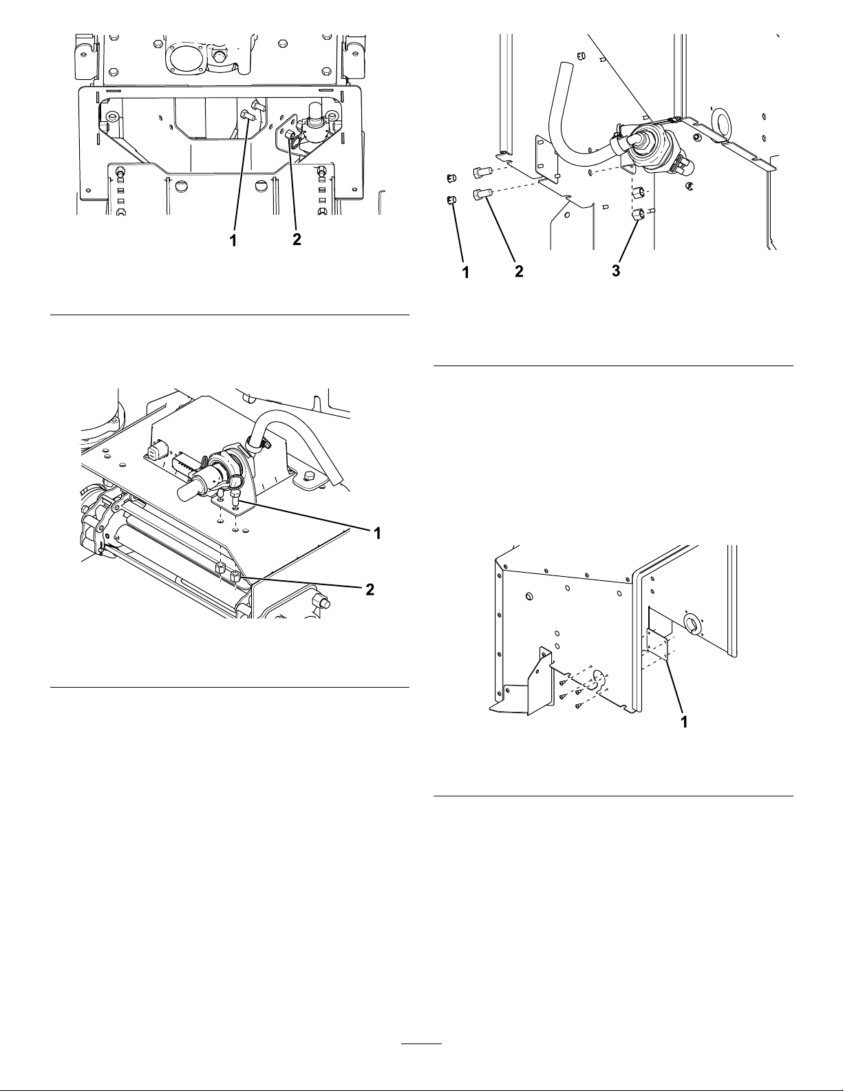
•For VBX spreaders, remove the plastic clips
securing the rear cover to the hopper ( Figure
1).
g029502
Figure 1
1. Plastic clip 2. Rear cover
•For Forge spreaders, remove the bolts
securing the rear cover to the hopper ( Figure
2).
g223387
Figure 2
1. Bolt 2. Rear cover
6. Carefully pull away the rear cover and unplug
the cover harness from the control module.
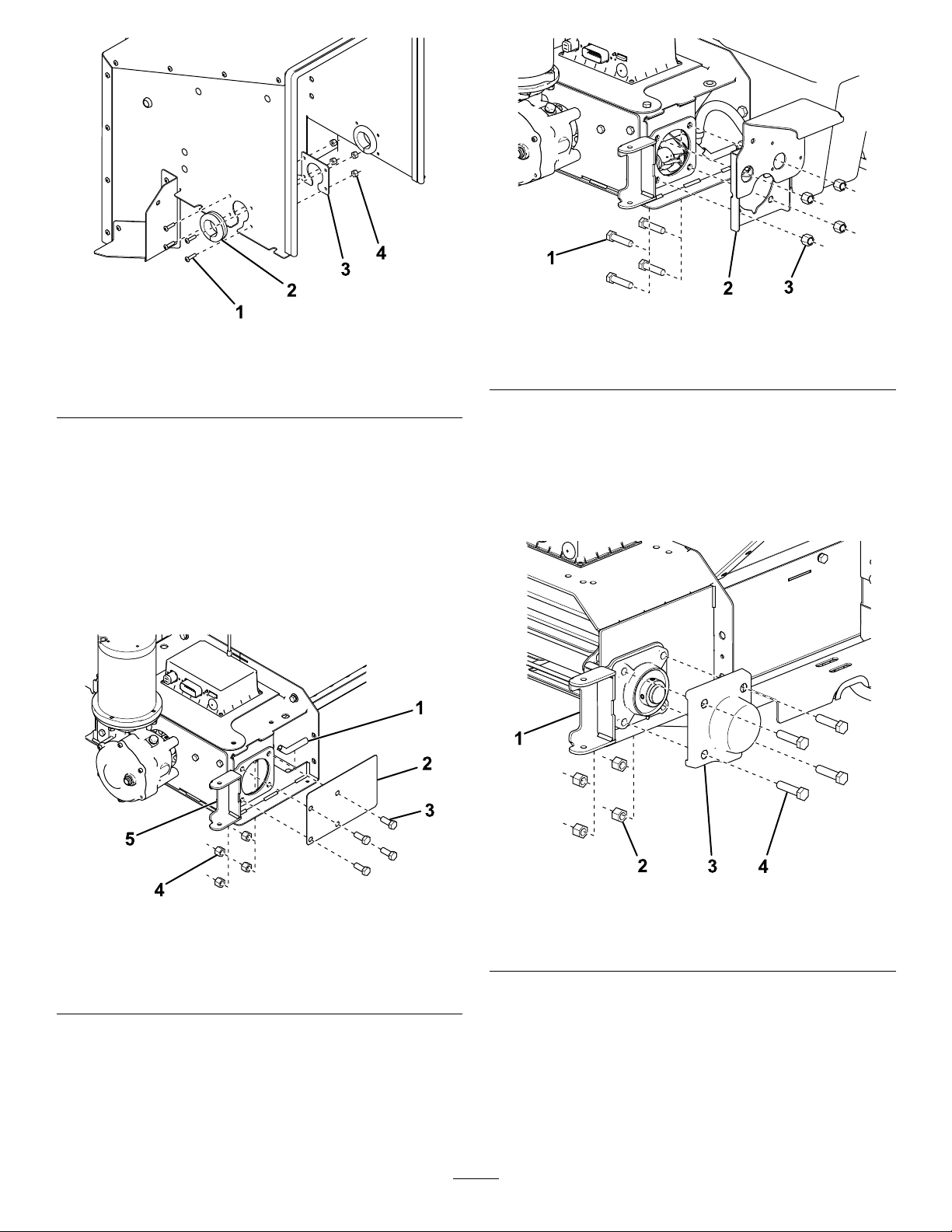
7. Slide both the long and short frame rails under
the legs of the spreader ( Figure 3 ). If you are
installing the kit onto a VBX 6500 or Forge 1.0
spreader , you do not need the short frame rails.
If installing the kit onto a VBX spreader , use the
wide L-brackets for the hopper legs closest to
the pre-wet tank.
g436603
Figure 3
1. Short frame rail 4. Bolt (3/8 inch)
2. T ap plate
5. Long frame rail
3. L-bracket
6. L-bracket (wide)
2

8. Complete one of the procedures below .
•VBX 8000/9000 models only: loosely
mount the 8 L-brackets to the rails near each
spreader leg using 16 bolts (3/8 inch) and 8
tap plates ( Figure 3 ).
•VBX 6500 models only: loosely mount the
6 L-brackets to the rails near each spreader
leg using 12 bolts (3/8 inch) and 6 tap plates
(Figure 3 ).
•Forge 1.0 models only: loosely mount the
2 L-brackets to the rails near each spreader
leg using 4 bolts (3/8 inch) and 2 tap plates
(Figure 3 ).
•Forge 1.5/20 models only: loosely mount
the 4 L-brackets near each spreader leg
using 8 bolts (3/8 inch) and 4 tap plates
(Figure 3 ).
9. Attach a 90 ° hose tting to the tank ( Figure 4 ).
Note: Ensure that the 90 ° hose tting is angled
as shown in Figure 4 .
g223403
Figure 4
1. 90 ° hose tting 3. 2.4 m (96 inch) hose
2. Hose clamp
10. Secure an end of the 2.4 m (96 inch) hose to the
90 ° hose tting with a hose clamp ( Figure 4 ).
1 1. Slide the tank into the space behind the
spreader , but leave room to work.
12. Insert the T end of the tank straps into the back
of the frame rails and twist them 90 ° to secure
(Figure 5 ).
g223404
Figure 5
1. T ank strap 2. Frame rail
13. Drape the straps over the tank and loosely
secure them to the frame rails using a carriage
bolt and jam nut ( Figure 6 ).
g436606
Figure 6
1. Carriage bolt
2. Jam nut
14. Slide the tank forward until it contacts the
spreader hopper .
15. Slide the L-brackets against the spreader legs
and loosely secure them to the spreader using 2
lag bolts (5/16 inch) on each bracket ( Figure 7 ).
3

g436607
Figure 7
1. Lag bolt (5/16 inch)
2. L-bracket
16. T ighten the fasteners on the L-brackets and tank
straps.
Installing the Spray Nozzle
1. Connect the spray nozzle, quick coupler , and
bulkhead to the nozzle mounting bracket as
shown in Figure 8 .
g223377
Figure 8
1. Spray nozzle 4. Gasket
2. Quick coupler
5. Nozzle mounting bracket
3. Bulkhead
2. Install a 90 ° hose tting onto the end of the
bulkhead ( Figure 9 ).
g223378
Figure 9
1. Bulkhead 3. Hose clamp
2. 90 ° hose tting 4. 45 cm (18 inch) hose
3. Secure the 45 cm (18 inch) hose to the 90 ° hose
tting with a hose clamp ( Figure 9 ).
4. Mount the nozzle bracket to the spreader
using 2 bolts (3/8 inch) and nuts in the location
described below:
Note: Ensure that the slit in the nozzle is
pointing down.
•For auger spreaders, mount the bracket to
the auger trough as shown in Figure 10 .
4

g223379
Figure 10
1. Bolt (3/8 inch) 2. Nut (3/8 inch)
•For VBX pintle chain spreaders, mount
the bracket to the top of the pintle chain
assembly as shown in Figure 1 1 .
g223380
Figure 1 1
1. Bolt (3/8 inch) 2. Nut (3/8 inch)
•For the Forge pintle chain spreaders, remove
the 2 plugs on the rear cover and mount the
bracket through them as shown in Figure 12 .
g225448
Figure 12
1. Plug (discard) 3. Nut (3/8 inch)
2. Bolt (3/8 inch)
5. T ighten all of the fasteners.
Installing the Pump
For the Forge Spreaders
1. Remove the grommet cover plate on the right
side of the rear cover ( Figure 13 ).
g223381
Figure 13
1. Grommet cover plate (remove)
2. Secure the grommet plate to the inside of the
rear cover using 4 bolts (#10 x 3/4 inch) and
nylon nuts ( Figure 14 ).
5

g223382
Figure 14
1. Bolt (#10 x 3/4 inch) 3. Grommet plate
2. Rubber grommet
4. Nylon nut (#10)
3. Insert the rubber grommet into the opening on
the grommet plate ( Figure 14 ).
4. If you have a pintle chain Forge spreader ,
continue to step 7. For the auger Forge
spreaders, remove and retain the 4 bolts and
nuts securing the right spinner-assembly pin
lock and auger sideplate to the auger assembly
(Figure 15 ).
Note: Discard the auger sideplate.
g223383
Figure 15
1. Edge cover 4. Nut
2. Auger sideplate (discard) 5. Spinner-assembly pin lock
3. Bolt
5. Slide 1 of the edge covers onto the opening in
the auger assembly ( Figure 15 ).
6. Secure the pump bracket to the auger assembly
using the previously removed 4 bolts and nuts
(Figure 16 ), then continue to step 9.
g223385
Figure 16
1. Bolt 3. Nut
2. Pump bracket
7. Remove and discard the 4 bolts and nuts
securing the right spinner-assembly pin lock
and bearing cover to the pintle chain assembly
(Figure 17 ).
Note: Do not discard the spinner-assembly pin
lock or bearing cover .
g223384
Figure 17
1. Spinner-assembly pin lock
3. Bearing cover
2. Nut (discard) 4. Bolt (discard)
8. Secure the pump bracket to the pintle chain
assembly using 4 bolts (1/2 inch) and nuts
(Figure 16 ).
6

g223385
Figure 18
1. Bolt (1/2 inch) 3. Nut (1/2 inch)
2. Pump bracket
9. T ighten the fasteners.
10. Install a 90 ° hose tting onto both sides of the
pump ( Figure 19 ).
g224963
Figure 19
1. 90 ° hose tting
1 1. Secure the pump to the pump bracket using 4
bolts (#10 x 1-1/4 inches), washers, and nylon
nuts ( Figure 20 ).
Note: T ighten the fasteners until the bolts are
ush with the nuts.
g224964
Figure 20
1. Nylon nut (#10) 4. W asher (#10)
2. Pump bracket
5. Bolt (#10 x 1-1/4 inches)
3. Pump
12. Locate and remove the plug on the control
module ( Figure 21 ).
g223388
Figure 21
1. Plug
2. Control module
13. Bring the rear cover close to the spreader and
route the pump connector through the previously
installed grommet ( Figure 22 ). For the pintle
chain Forge spreaders, route the 45 cm (18
inch) hose from the spray nozzle through the
grommet as well.
7

g224965
Figure 22
1. Rubber grommet 3. Pump connector wire
2. 45 cm (18 inch) hose
14. Connect the pump connector and cover harness
to the control module ( Figure 21 ).
15. Secure the rear cover to the spreader with the
previously removed bolts and washers.
16. Secure the 45 cm (18 inch) hose from the spray
nozzle to the hose tting on the right side of the
pump with a hose clamp ( Figure 23 ).
Note: If you have an auger spreader , trim the
hose to prevent it from kinking.
g223394
Figure 23
1. Hose clamp
3. Spray nozzle hose
2. 1.2 m (48 inch)
17. Secure the 1.2 m (48 inch) hose to the hose
tting on the left side of the pump with a hose
clamp ( Figure 23 ).
18. Route the hose under the frame rail, toward the
lter ( Figure 23 ).
For VBX Spreaders
1. For auger spreaders, slide 1 of the edge covers
onto the opening in the auger assembly as
shown in Figure 24 .
g223392
Figure 24
1. Spinner-assembly pin lock 3. Bolt (discard)
2. Nut (discard)
4. Edge cover
2. Remove and discard the 4 bolts and nuts
securing the right spinner-assembly pin lock to
the auger or pintle chain assembly ( Figure 24 ).
Do not discard the spinner-assembly pin lock.
3. Secure the pump bracket to the auger or pintle
chain assembly using 4 bolts (1/2 inch) and nuts
(Figure 25 ).
g223385
Figure 25
1. Bolt (1/2 inch) 3. Nut (1/2 inch)
2. Pump bracket
4. T ighten the fasteners.
5. Install a 90 ° hose tting onto both sides of the
pump ( Figure 26 ).
8

g224963
Figure 26
1. 90 ° hose tting
6. Secure the pump to the pump bracket using 4
bolts (#10 x 1-1/4 inches), washers, and nylon
nuts ( Figure 27 ).
Note: T ighten the fasteners until the bolts are
ush with the nuts.
g224964
Figure 27
1. Nylon nut (#10) 4. W asher (#10)
2. Pump bracket
5. Bolt (#10 x 1-1/4 inches)
3. Pump
7. Locate and remove the plug on the control
module ( Figure 28 ).
g223388
Figure 28
1. Plug
2. Control module
8. Connect the pump connector to the control
module ( Figure 28 ).
9. Secure the 45 cm (18 inch) hose from the spray
nozzle to the hose tting on the right side of the
pump with a hose clamp ( Figure 29 ).
Note: If you have an auger spreader , trim the
hose to prevent it from kinking.
g223394
Figure 29
1. Hose clamp
3. Spray nozzle hose
2. 1.2 m (48 inch) hose
10. Secure the 1.2 m (48 inch) hose to the hose
tting on the left side of the pump with a hose
clamp ( Figure 29 ).
1 1. Route the hose under the frame rail, toward the
lter ( Figure 29 ).
12. Connect the cover harness to the control module
and install the previously removed rear cover .
9

Connecting the Ball V alve
and Filter
1. Attach the 3 hose clips to the long tank hose and
secure them to the underside of the frame rail
using 3 bolts (1/4 x 1 inch) and nuts ( Figure 30 ).
g224966
Figure 30
1. T ank hose 3. Hose clip
2. Bolt (1/4 x 1 inch) 4. Nut (1/4 inch)
2. T ighten the fasteners.
3. Install a 90 ° hose tting onto the bottom of the
ball valve ( Figure 31 ).
g224967
Figure 31
1. 9.5 cm (4-3/4 inches) hose
4. Ball valve
2. Hose clamp
5. 90 ° hose tting
3. Straight hose tting
4. Install a straight hose tting onto the top of the
ball valve ( Figure 31 ).
5. Secure the 9.5 cm (4-3/4 inches) hose to the
straight hose tting with a hose clamp ( Figure
31 ).
6. Install a 90 ° hose tting on both sides of the
lter ( Figure 32 ).
g224968
Figure 32
1. 90 ° hose tting
3. Hose clamp
2. Filter
7. Secure the 9.5 cm (4-3/4 inches) hose to the
right 90 ° hose tting with a hose clamp ( Figure
32 ).
Note: Ensure that the arrow on the lter is
pointing to the rear of the vehicle.
Mounting the Filter and
Securing the Hoses
1. For the Forge spreaders, continue to step 4. For
VBX spreaders, line up the lter bracket with the
edge of the rear cover and mount it to the hopper
with 4 bolts (5/16 inch) as shown in Figure 33 .
g224969
Figure 33
1. Filter bracket
2. Bolt (5/16 inch)
2. T ighten the fasteners.
10

3. Mount the lter to the lter bracket using 2 bolts
(1/4 x 3 inches) and nuts ( Figure 34 ), then
continue to step 5.
g224970
Figure 34
1. Nut (1/4 inch) 2. Bolt (1/4 x 3 inches)
4. Mount the lter to the spreader leg using 2 bolts
(1/4 x 3 inches) and nuts ( Figure 35 ).
g224971
Figure 35
1. Bolt (1/4 x 3 inches) 3. Spreader leg
2. Nut (1/4 inch)
5. T ighten the fasteners.
6. Secure the 1.2 m (48 inch) hose from the pump
to the 90 ° lter hose tting with a hose clamp
(Figure 36 ).
Note: Ensure that the hose is routed under the
frame rail and out the side near the lter .
g224972
Figure 36
1. 90 ° lter hose tting 4. 90 ° ball valve hose tting
2. Hose clamp 5. T ank hose
3. Pump hose 6. Edge cover
7. Secure the free end of the tank hose to the 90 °
ball valve hose tting with a hose clamp ( Figure
36 ).
Note: For VBX 6500 and Forge 1.0 spreaders,
trim the hose to prevent it from kinking.
8. Slide 1 of the edge covers onto the frame rail
as shown in Figure 36 .
9. For the Forge spreaders, continue to step 1 1 .
For the VBX spreaders, secure the hose retainer
to the spreader leg using 2 lag bolts (5/16 inch)
as shown in Figure 37 .
g223401
Figure 37
1. Hose retainer
2. Lag bolt (5/16 inch)
10. T ighten the fasteners.
1 1

1 1. Attach the previously removed spinner
assembly; refer to your spreader Owner ’ s
Manual .
12. Connect the spreader power/ground cable to the
main wire harness.
Connecting the Ball V alve
and Filter
1. Attach the 3 hose clips to the long tank hose and
secure them to the underside of the frame rail
using 3 bolts (1/4 x 1 inch) and nuts ( Figure 30 ).
g224966
Figure 38
1. T ank hose 3. Hose clip
2. Bolt (1/4 x 1 inch) 4. Nut (1/4 inch)
2. T ighten the fasteners.
3. Install a 90 ° hose tting onto the bottom of the
ball valve ( Figure 31 ).
g224967
Figure 39
1. 9.5 cm (4-3/4 inches) hose
4. Ball valve
2. Hose clamp
5. 90 ° hose tting
3. Straight hose tting
4. Install a straight hose tting onto the top of the
ball valve ( Figure 31 ).
5. Secure the 9.5 cm (4-3/4 inches) hose to the
straight hose tting with a hose clamp ( Figure
31 ).
6. Install a 90 ° hose tting on both sides of the
lter ( Figure 32 ).
g224968
Figure 40
1. 90 ° hose tting
3. Hose clamp
2. Filter
7. Secure the 9.5 cm (4-3/4 inches) hose to the
right 90 ° hose tting with a hose clamp ( Figure
32 ).
Note: Ensure that the arrow on the lter is
pointing to the rear of the vehicle.
12

Operation
Filling the T ank1. Clean around the tank cap ( Figure 41 ).
g436608
Figure 41
1. T ank cap
2. Remove the tank cap and ll the tank with your
brine solution.
Note: The marks on the tank are in 37.8 L (10
US gallons) increments.
Important: Use only pre-mixed brine to
prevent dangerous chemical reactions.
3. Wipe any spills and secure the tank cap.
Operating the Pre-W et
System
Note: Refer to your spreader Owner ’ s Manual for
controller operation.
Once the pre-wet system has been installed, Pre-W et
will appear on your controller as shown in Figure 42 .
g223060
Figure 42
1. Pre-W et icon
The pre-wet system is only active when it is highlighted
on the controller . When the system is active, it
sprays the brine solution whenever the spreader
feeder-motor is active.
Activating the Pre-W et System
1. T o activate the pre-wet system, press the Mode
button on the controller ( Figure 43 ).
g223061
Figure 43
1. Mode button
2. Press the Pre-W et button ( Figure 44 ).
g223062
Figure 44
1. Pre-W et button
13

3. On the pre-wet screen, press the Pre-W et button
(Figure 45 ).
Note: Once Pre-W et is highlighted, the system
is active.
g223063
Figure 45
1. Pre-W et button
Setting the Flow Speed
1. T o set the ow speed, press the Mode button on
the controller ( Figure 46 ).
g223064
Figure 46
1. Mode button
2. Press the Pre-W et button ( Figure 47 ).
g223065
Figure 47
1. Pre-W et button
3. On the pre-wet screen, press the Flow button
to cycle between the ow speeds ( Figure 48 ).
There are 4 speeds: Flow 1 is the lowest and
Flow 4 is the highest.
g223066
Figure 48
1. Flow button
Deactivating the Pre-W et System
1. T o deactivate the pre-wet system, press the
Mode button on the controller ( Figure 49 ).
g223064
Figure 49
1. Mode button
2. Press the Pre-W et button ( Figure 50 ).
g223065
Figure 50
1. Pre-W et button
14

3. On the pre-wet screen, press the Pre-W et button
(Figure 51 ).
Note: Once Pre-W et is no longer highlighted,
the system is inactive.
g223067
Figure 51
1. Pre-W et button
Emptying the T ank
Conguring the Dump Switch
The tank can be emptied by using the spreader dump
switch, but it must be congured rst.
1. T o congure the dump switch, press the Mode
button on the controller ( Figure 52 ).
g223064
Figure 52
1. Mode button
2. Press the Pre-W et button ( Figure 53 ).
g223065
Figure 53
1. Pre-W et button
3. On the pre-wet screen, press the Dump button
(Figure 54 ).
g223068
Figure 54
1. Dump button
4. On the dump screen, select which material you
want the dump switch to dump ( Figure 55 ).
Press the Solid button to dump only the material
in the spreader hopper . Press the Liquid button
to dump only the solution in the tank. Y ou can
select and dump both materials at the same
time.
Note: Once the material type is highlighted, it
dumps out when you press the dump switch.
g223069
Figure 55
1. Solid button
2. Liquid button
15

Using the Dump Hose
1. Position the spreader in the area where you
want to deposit the material, engage the parking
brake, shut of f the engine, and remove the key .
2. Disconnect the spreader power/ground cable
from the wire harness.
3. Unplug the spreader spinner harness from the
main wire harness.
4. Remove the right latch and cotter pin from the
spreader spinner assembly ( Figure 56 ).
g223405
Figure 56
1. Cotter pin
2. Latch pin
5. Swing the spreader spinner assembly free from
the hopper opening ( Figure 56 ).
Note: Do not move the vehicle when the
spinner assembly is swung out.
6. Locate the spray nozzle underneath the rear
cover ( Figure 57 ).
Note: Y ou do not need to remove the rear cover
to empty the tank.
g223406
Figure 57
1. Spray nozzle
7. Raise the latches on the quick coupler and
remove the spray nozzle ( Figure 58 ).
g223407
Figure 58
1. Spray nozzle 2. Quick coupler latch
8. Connect the dump hose quick coupler to the
nozzle quick coupler and lower the latches to
lock it in place ( Figure 59 ).
16

g223408
Figure 59
1. Dump hose 2. Nozzle quick coupler
9. Connect the spreader power/ground cable to
the wire harness and power the vehicle, but do
not start it.
10. Push and hold the dump switch to unload the
tank solution.
1 1. Shut of f the vehicle, remove the keys, and
disconnect the spreader power/ground cable
from the wire harness.
12. Raise the latches on the quick coupler and
remove the dump hose ( Figure 59 ).
13. Slide the spray nozzle into the quick coupler and
lower the latches to lock it in place ( Figure 58 ).
Note: Ensure that the slit in the nozzle is
pointing down.
14. Swing the spreader spinner assembly back into
place and secure it with the previously removed
attachment pin and cotter pin.
15. Connect the spreader spinner harness to the
main wire harness.
16. Connect the spreader power/ground cable to
the wire harness.
Operating T ips
•Do not store materials in the tank.
•Close the ball valve when transporting the machine
while the pre-wet system is installed.
•Rinse the tank with fresh water before storing it.
17

T roubleshooting
Problem
Possible Cause Corrective Action
1. The pump is not connected to the
module.
1. Plug the pump into the module.
2. The white jumper wire is not connected.
2. Connect the white jumper wire.
Pre-W et does not appear on the controller .
3. The white jumper wire is corroded.
3. Check the white jumper wire for
corrosion and clean it if necessary .
The controller shows “Pre-W et Error .”
1. The pump circuit is open, has a short,
or is drawing too much current.
1. Check the pump power/ground,
connector terminals, lter , and hoses
for damage and replace or clean them
if necessary .
1. The pump is not connected to the
module.
1. Plug the pump into the module.The pump does not engage.
2. There is no power or ground to the
module.
2. Check for power and ground at the
module.
1. The ball valve is closed.
1. Open the ball valve.
2. The lter is clogged. 2. Clean the lter .
The pump does not prime.
3. The brine in the hoses is frozen.
3. Bring the spreader to a warm area to
thaw .
1. The spray nozzle is plugged or frozen. 1. Clean the spray nozzle.The pump runs and shuts of f repeatedly .
2. The brine in the hoses is frozen.
2. Bring the spreader to a warm area to
thaw .
1. The ball valve is closed.
1. Open the ball valve.
2. The lter is clogged. 2. Clean the lter .
3. The spray nozzle is plugged or frozen. 3. Clean the spray nozzle.
4. The brine in the hoses is frozen.
4. Bring the spreader to a warm area to
thaw .
The pre-wet system is not spraying.
5. The hoses are clogged.
5. Clean the hoses.
Brine is dripping from the spray nozzle
when the system is not in use.
1. The ball valve is open.
1. Close the ball valve.
T oo much brine is being sprayed.
1. The ow is set too high. 1. Lower the ow level; refer to Setting
the Flow Speed.
T oo little brine is being sprayed.
1. The ow is set too low . 1. Raise the ow level; refer to Setting
the Flow Speed.
1. Nothing is selected in the Dump menu.
1. Select the material you want to dump
in the Dump menu; refer to Conguring
the Dump Switch.
Nothing happens when the dump switch
is pressed.
2. The dump switch is broken.
2. Check the terminals on the back of the
dump switch. Repair or replace the
switch if necessary .
Brine does not dump when pressing the
dump switch.
1. “Liquid” is not selected in the Dump
menu.
1. Select “Liquid” in the Dump menu;
refer to Conguring the Dump Switch.
Dry material does not dump when pressing
the dump switch.
1. “Solid” is not selected in the Dump
menu.
1. Select “Solid” in the Dump menu; refer
to Conguring the Dump Switch.
Brine dumps when pressing the dump
switch and I do not want it to.
1. “Liquid” is selected in the Dump menu. 1. Deselect “Liquid” in the Dump menu;
refer to Conguring the Dump Switch.
Dry material dumps when pressing the
dump switch and I do not want it to.
1. “Solid” is selected in the Dump menu. 1. Deselect “Solid” in the Dump menu;
refer to Conguring the Dump Switch.
18

Notes:

Table of contents