BOSSCO RPS-10 User manual

p
RPS-I0
DIGITAL
PITCH
SHIFTER
/
DELAY
|
INSTRUCTIONS
Please
read
the
instructions
carefully.
The
RPS-10
features
two
functions;
Pitch
Shifter
and
Digital
Delay.
e
When
used
as
a
pitch
shifter,
the
RPS-10
allows
pitch
shifting
freely
from
—1
to
+1
octave.
è
Setting
up
a
keyboard,
desired
pitch
shifting
can
be
selected
at
once.
e
The
newly
developed
LSI
enables
to
reduce
the
possible
tremolo
and
time
lug.
e
When
used
as
a
delay
machine,
the
RPS-10
allows
to
set
the
delay
time
from
25
to
800ms.
e
The
direct
sound
has
frequency
response
from
20Hz
to
30kHz
and
the
effect
sound
from
40Hz
to
15kHz.
r
e
in
both
Pitch
Shifter
and
Delay
modes,
the
INV
(invert)
position
serves
to
create
tape
recorder’s
reverse
playback
like
effect.
CONTENTS
[1]
Connections
................aiasieieewanen
anae
en
eaaa
teens
4
[Z]
Pitch
Shifter
................
aaa
anaa
aia
eee
6
1.
Pitch
Shifting
with
the
Control
Knobs
............
6
2.
Pitch
Shifting
with
the
External
Keyboard
.....
8
[3]
Dela,
sia
ranah
NA
uot
Ng
gaga
Bg
aken
11
[4]
Setting
Examples
0000000000...
12
[5]
Important
Notes
0.00.0.
14
[6]
Specifications
..................
cece
15
RADIO
AND
TELEVISION
INTERFERENCE
“Warning
-
This
equipment
has
been
verified
to
comply
with
the
limits
for
a
Class
8
compuüng
device
pursuant
to
Subpart
J,
of
Part
15,
of
FCC
rules.
Operation
with
non-certified
of
non-vertied
equip
ment
is
bkely
ta
result
in
interference
to
radio
and
TY
reception.”
The
equipment
described
in
this
manual
generates
and
uses
radio-frequency
energy.
ff
it
is
not
installed
and
used
property.
that
is,
in
strict
accordance
with
our
instructions,
it
may
cause
interfer.
ence
with
radio
and
television
reception
Tris
equipment
has
been
tested
and
found
to
comply
with
the
limits
for
a
Ciass
B
computing
device
in
accorgance
with
the
specifications
in
Subpart
J,
of
Part
15.
of
FCC
Rules.
These
ruies
are
designed
to
provide
reasonable
protection
against
such
a
interference
in
a
residential
instailauon
However,
there
is
no
guarantee
that
the
interference
will
not
occur
in
a
particular
installation.
if
this
equipment
goes
cause
interference
to
radio
or
television
reception,
which
can
be
determinea
by
turning
the
equipment
on
and
off,
the
user
ts
encouraged
to
try
to
correct
the
interference
by
the
following
measure:
s
Disconnect
other
devices
and
their
input
output
cables
one
at
a
time.
if
the
interference
stops,
it
is
caused
by
either
the
other
device
or
its
LO
cable.
These
devices
usually
require
Roland
designated
shielded
10
cabies.
For
Roiand
cevices.
you
can
obtain
the
proper
shielded
cable
from
your
dealer.
For
non
Roland
devices,
contact
the
manufacturer
or
dealer
tor
assistance.
if
your
equipment
does
cause
interference
to
radio
or
television
reception,
you
can
try
to
correct
the
interference
by
using
one
or
more
of
the
following
measures:
e
Turn
the
TV
or
radio
antenna
until
the
interferences
stops.
è
Move
the
equipment
to
one
side
or
the
other
of
the
TV
or
radio
e
Move
the
equipment
farther
away
from
the
TV
or
radio.
ə
Plug
the
equipment
into
‘an
outlet
that
is
on
a
different
circuit
than
the
TV
or
radio.
(That
is,
make
certain
the
equipment
and
the
radio
or
television
set
are
on
circuits
controlled
by
different
circuit
breakers
or
fuses.
e
consider
installing
a
rooftop
television
antenna
with
coaxial
cabie
lead-in
between
the
antenna
and
v
if
necessary,
you
should
consult
your
dealer
or
an
experienced
radio
television
technician
for
additional
suggestions.
You
may
find
helpful
the
following
booklet
prepared
by
the
‘Federal
Com.
mumecations
Commision
:
“How
to
identify
and
Resolve
Radio-TV
interference
Problems”
This
booklet
is
avaiabie
from
the
U.S.
Government
Printing
Office.
Wasnington.
DC.,
20402,
Stock
No.
004-000-00345-4
Bescheinigung
des
Herstellers
/Importeurs
Hiermit
wird
bescheinigt,
daß
der/die/das
BOSS
DIGITAL
PITCH
SHIFTER/DELAY
RPS-10
IGerat.
Typ
Bezeichnung)
in
Ubereinstimmung
mit
den
Bestimmungen
der
Amtsbl.
Vfg
1046
/
1984
(Amteblativerfugung)
funk-entstort
ist.
Der
Deutschen
Bundespost
wurde
das
Inverkehrbringen
dieses
Gerates
angezeigt
und
die
Berechtigung
zur
Uberprufung
der
Serie
auf
Einhaltung
der
Bestimmungen
eingeraumt.
Roland
Corporation
Osaka
/
Japan
Name
des
Hersteliers/importeurt
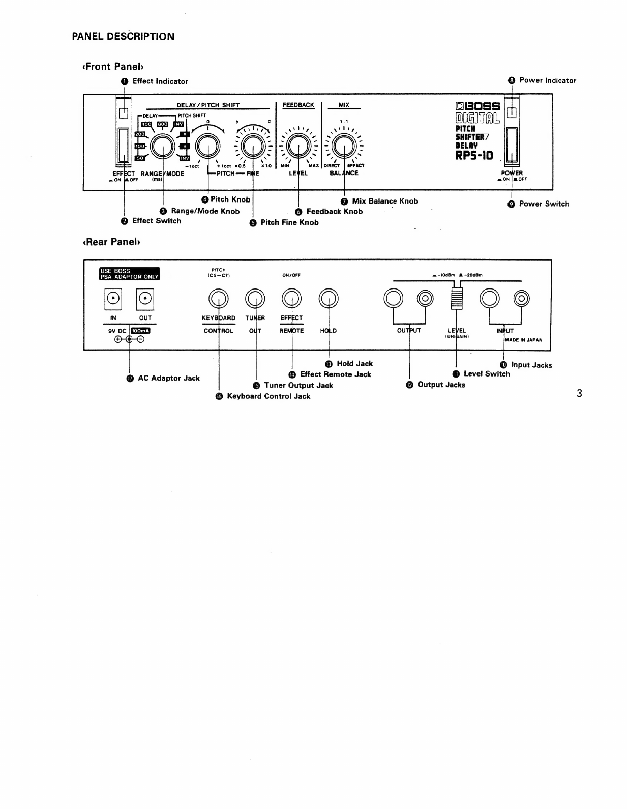
PANEL
DESCRIPTION
«Front
Paneb
©
Effect
indicator
DELAY
/
PITCH SHIFT
PITCH
SHIFT
b 3
r
vi;
TIN
@
Pitch
Knob
«Rear
Paneb
USE
BOSS
PITCH
PSA
ADAPTOR
ONLY
(C5—C7)
ON/OFF
©
OQ
Q
KEYBDARD
TUNER
EFFECT
ov
DC
ENID
CONTROL
OUT
REMOTE
DAS
@
AC
Adaptor
Jack
@
Mix
Balance
Knob
©
Range/Niode
Knob
.
@
Feedback
Knob
i
@
Effect
Switch
©
Pitch
Fine
Knob
®
Hold
Jack
©
Effect
Remote
Jack
©
Tuner
Output
Jack
@
Keyboard
Control
Jack
©
Power
Indicator
oBoss
|
1
DIGITAL
PITCH
SHIFTER
/
DELAY
©
Power
Switch
æ
-10dBm
M
-20d8m
OC
©
INPUT
MADE
IN
JAPAN
(UNIGAIN)
@
Input
Jacks
@
Level
Switch
©
Output
Jacks

[1]
CONNECTIONS
Power
Supply
BOSS
RPW-7
jesamaal
Video
Cassette
Recorder
AC
Adaptor
BOSS
PSA-120,
220,
240
(Optional)
(een
pe
peg
Oct
CD
Player
To
other
BOSS
Micro
Studio
Series
;
erc
e]
To
INPUT
Video
Disc
Player
5
iy
USE
BOSS
PSA
ADAPTOR
ONLY
be
Footswitch
FS-1
Footswitch
FS-1
or
ul
(Optional)
Pedalswitch
DP-2
{Optional)
ate
Tape
Recorder
FM/TV
Tuner
Tum
AN
OOTHTHO
O
From
OUTPUT
All
the
BOSS
Micro
Studio
Series
show
the
current
draw
here
Guitar
Amplifier
Audio
Out
Electric
Keyboard
aw
aa
aaa
p
aaa
a
aaa
[mmm
Omme]
|
4
ANAN
AAN
AH
Tape
Recorder

@
INPUT
JACKS
The
standard
phone
jack
and
the
pin
jack
cannot
be
used
at
a
time.
If
both
are
connected,
the
standard
phone
jack
will
work.
@
LEVEL
SWITCH
Set
this
switch
depending
on
the
output
level
of
the
connected
device.
If
the
sound
is
distorted
at
the
"“-20dBm”
position,
change
the
switch
to
the
“—~10dBm”
position.
@
OUTPUT
JACKS
Both
the
standard
phone
and
pin
jacks
can
be
simul-
taneously
used.
`
®©
HOLD
JACK
By
connecting
the
footswitch
FS-1
(optional)
to
the
Hold
Jack,
the
effect
sound
can
be
sustained
with
the
pedal
operation.
*
Please
do
not
switch
on
or
off
the
unit
while
the
Hold
effect
is
on.
@
EFFECT
REMOTE
JACK
By
connecting
the
footswitch
FS-1
(optional),
the
Normal
or
the
Effect
mode
can
be
selected
with
the
pedal
operation.
*
Please
make
sure
that
the
Effect
Switch
is
turned
on.
[2]
PITCH
SHIFTER
The
amount
of
the
pitch
shifting
can
be
set
within
a
range
of
—1
to
+1
octave.
The
amount
of
the
pitch
shifting
can
be
controlled
either
with
the
knobs
on
the
RPS-10
or
externally
by
the
keyboard.
By
connecting
a
chromatic
tuner
such
as
TU-12,
TU-12H,
TU-100,
the
amount
of
the
pitch
shifting
set
on
the
RPS-10
can
be
seen
in
the
Display
and
the
Meter
of
the
tuner.
When
all
the
necessary
connections
are
made,
turn
the
RPS-10
on.
*
Turn
the
amplifier
on
in
the
end.
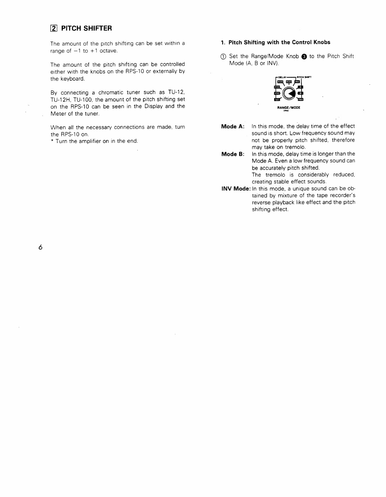
1.
Pitch
Shifting
with
the
Control
Knobs
@
Set
the
Range/Mode
Knob
@
to
the
Pitch
Shift
Mode
(A,
B
or
INV).
Mode
A:
Mode
B:
INV
Mode:
«EG:
aa
hm
CH
SHIFT
RANGE
/MODE
(ma)
In
this
mode,
the
delay
time
of
the
effect
sound
is
short.
Low
frequency
sound
may
not
be
properly
pitch
shifted,
therefore
may
take
on
tremolo.
In
this
mode,
delay
time
is
longer
than
the
Mode
A.
Even
a
low
frequency
sound
can
be
accurately
pitch
shifted.
The
tremolo
is
considerably
reduced,
creating
stable
effect
sounds.
In
this
mode,
a
unique
sound
can
be
ob-
tained
by
mixture
of
the
tape
recorder’s
reverse
playback
like
effect
and
the
pitch
shifting
effect.
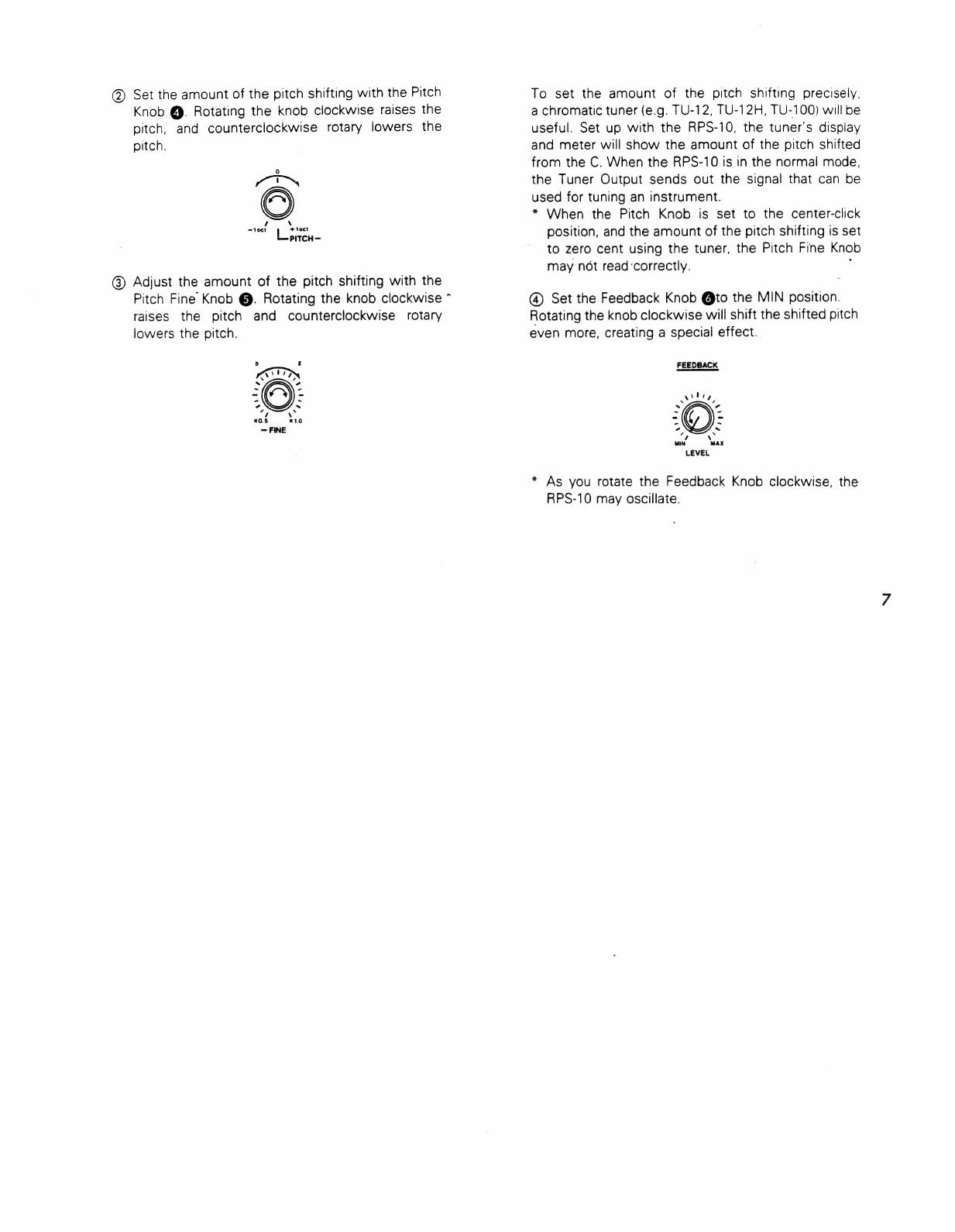
@)
Set
the
amount
of
the
pitch
shifting
with
the
Pitch
To
set
the
amount
of
the
pitch
shifting
precisely,
Knob
@.
Rotating
the
knob
clockwise
raises
the
a
chromatic
tuner
(e.g.
TU-12,
TU-12H,
TU-100)
will
be
pitch,
and
counterclockwise
rotary
lowers
the
useful.
Set
up
with
the
RPS-10,
the
tuner’s
display
pitch.
and
meter
will
show
the
amount
of
the
pitch
shifted
:
from
the
C.
When
the
RPS-10
is
in
the
normal
mode,
AON
the
Tuner
Output
sends
out
the
signal
that
can
be
used
for
tuning
an
instrument.
A
*
When
the
Pitch
Knob
is
set
to
the
center-click
ea
ea.
position,
and
the
amount
of
the
pitch
shifting
is
set
to
zero
cent
using
the
tuner,
the
Pitch
Fine
Knob
may
not
read
‘correctly.
@)
Adjust
the
amount
of
the
pitch
shifting
with
the
Pitch
Fine
Knob
@.
Rotating
the
knob
clockwise
^
(4)
Set
the
Feedback
Knob
@to
the
MIN
position.
raises
the
pitch
and
counterclockwise
rotary
Rotating
the
knob
clockwise
will
shift
the
shifted
pitch
lowers
the
pitch.
even
more,
creating
a
special
effect.
AKIN
FEEDBACK
O:
wily,
a)
nr
=
7
x0.5
x10
=
a
~
FINE
=
`
+ N
MIN
MAX
*
As
you
rotate
the
Feedback
Knob
clockwise,
the
RPS-10
may
oscillate.
®©
Using
the
Mix
Balance
Knob
@,
adjust
the
volume
balance
of
the
direct
and
the
effect
sounds.
MIX
N
2
~
Cd
=
~
r
~
a `
s
DIRECT
EFFECT
BALANCE
When
the
Mix
Balance
Knob
is
set
to
the
center-click
position,
the
volume
balance
is
almost
equal.
At
the
fully
clockwise
position,
only
the
direct
sound
is
heard,
and
at
the
counterclockwise
position,
only
the
effect
sound
is
heard.
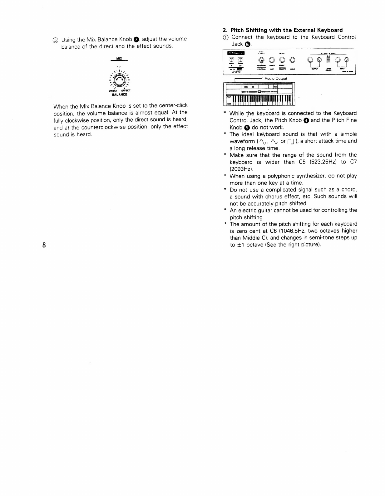
2.
Pitch
Shifting
with
the
External
Keyboard
®©
Connect
the
keyboard
to
the
Keyboard
Contro
Jack
0.
seen
SA
While
the
keyboard
is
connected
to
the
Keyboard
Control
Jack,
the
Pitch
Knob
@
and
the
Pitch
Fine
Knob
@
do
not:work.
The
ideal
keyboard
sound
is
that
with
a
simple
waveform
(“\,,
AN
or
[U
),
a
short
attack
time
and
a
long
release
time.
*
Make
sure
that
the
range
of
the
sound
from
the
keyboard
is
wider
than
C5
(523.25Hz)
to
C7
(2093Hz).
*
When
using
a
polyphonic
synthesizer,
do
not
play
more
than
one
key
at
a
time.
Do
not
use
a
complicated
signal
such
as
a
chord,
a
sound
with
chorus
effect,
etc.
Such
sounds
will
not
be
accurately
pitch
shifted.
An
electric
guitar
cannot
be
used
for
controlling
the
pitch
shifting.
*
The
amount
of
the
pitch
shifting
for
each
keyboard
is
zero
cent
at
C6
(1046.5Hz,
two
octaves
higher
than
Middle
C),
and
changes
in
semi-tone
steps
up
to
+1
octave
(See
the
right
picture).
*
*
*

+
12060
+1100
+1000
+
900
800
700
600
500
t444
Hot
+ +
+
Nm
=
EP
Shwe
ae
>
cam)
oO
C7
(2093Hz)
C6
(1056.5Hz)
C5
(523.25Hz)
C4
(Middle
C)
@
Set
the
(A,
B
or
Mode
A:
Mode
B:
INV
Mode:
Range/Mode
@
to
the
Pitch
Shift
Mode
INV).
RANGE
/MODE
In
this
mode,
the
delay
time
of
the
effect
sound
is
short.
Low-frequency
sound
may
not
be
properly
pitch
shifted,
therefore
may
take
on
tremolo.
In
this
mode,
delay
time
is
longer
than
the
Mode
A.
Even
a
low
frequency
sound
can
be
accurately
pitch
shifted.
The
tremolo
is
considerably
reduced,
creating
stable
effect
sounds.
In
this
mode,
a
unique
sound
can
be
ob-
tained
by
the
mixture
of
the
tape
recorder’s
reverse
playback
like
effect
and
the
pitch
shifting
effect.
@
Set
the
amount
of
the
pitch
shifting
with
the
Key-
board
connected
to
the
Keyboard
Control
Jack
@.

10
®©
Set
the
Feedback
Knob
@
to
the
MIN
position.
Rotating
the
knob
clockwise
will
shift
the
shifted
pitch
even
more,
creating
a
special
effect.
FEEDBACK
*
As
you
rotate
the
Feedback
Knob
clockwise,
the
RPS-10
may
oscillate.
®©
Using
the
Mix
Balance
Knob
@,
adjust
the
volume
balance
of
the
direct
and
the
effect
sounds.
~
s
em
-~
r `
A
x
4
`
DIRECY
EFFECT
BALANCE
When
the
Mix
Balance
Knob
is
set
to
the
center-click
position,
the
volume
balance
is
almost
equal.
At
the
fully
clockwise
position,
only
the
direct
sound
is
heard,
and
at
the
counterclockwise
position,
only
the
effect
sound
is
heard.
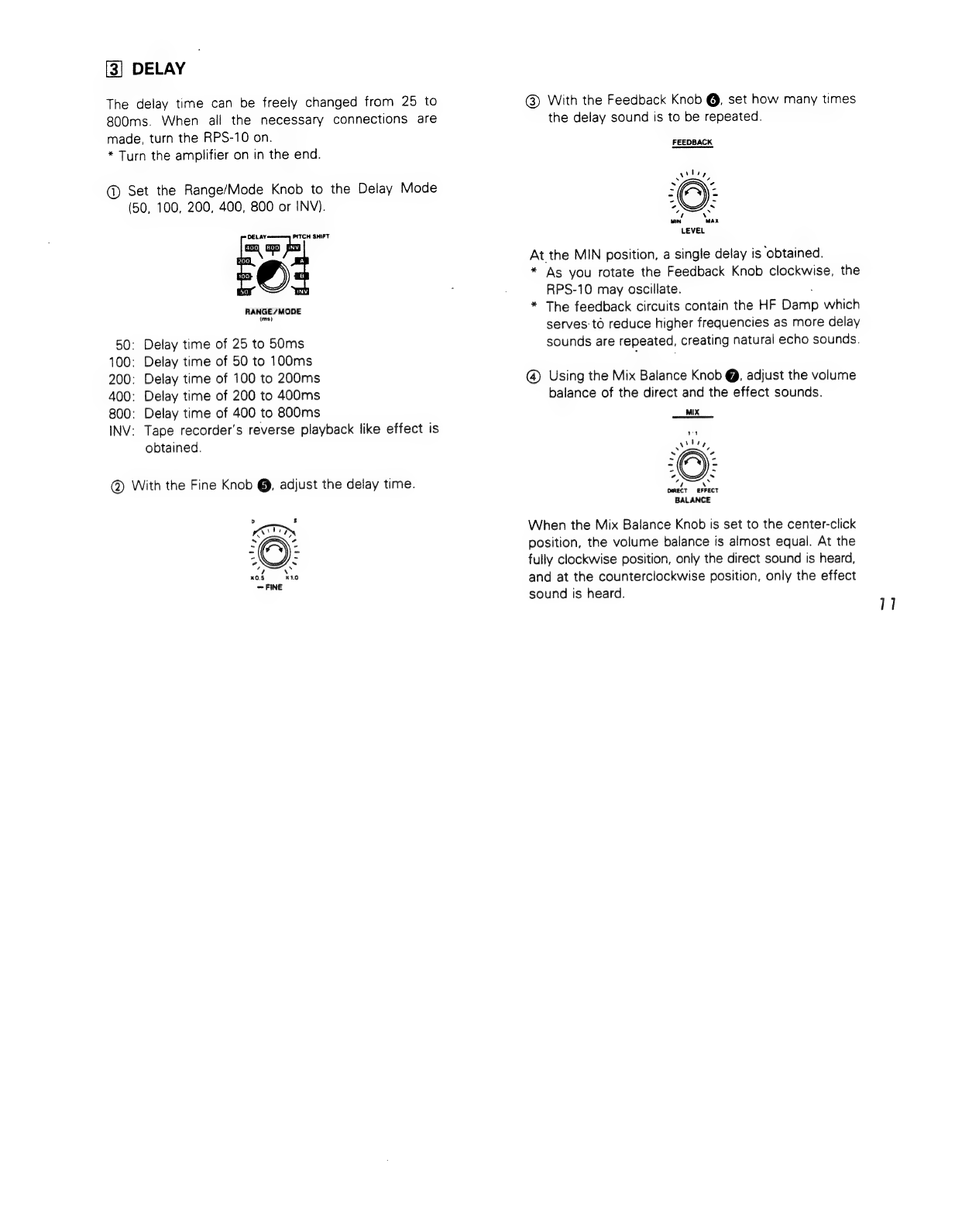
[3]
DELAY
The
delay
time
can
be
freely
changed
from
25
to
800ms.
When
all
the
necessary
connections
are
made,
turn
the
RPS-10
on.
*
Turn
the
amplifier
on
in
the
end.
@
Set
the
Range/Mode
Knob
to
the
Delay
Mode
(50,
100,
200, 400,
800
or
INV).
=
aa kn
PITCH
SHIFT
Ika
RANGE
/MODE
(ms)
50:
Delay
time
of
25
to
50ms
100:
Delay
time
of
50
to
100ms
200:
Delay
time
of
100
to
200ms
400:
Delay
time
of
200
to
400ms
800:
Delay
time
of
400
to
800ms
INV:
Tape
recorder’s
reverse
playback
like
effect
is
obtained.
@
With
the
Fine
Knob
@,
adjust
the
delay
time.
@
With
the
Feedback
Knob
@,
set
how
many
times
the
delay
sound
is
to
be
repeated.
FEEDBACK
At
the
MIN
position,
a
single
delay
is
obtained.
*
As
you
rotate
the
Feedback
Knob
clockwise,
the
RPS-10
may
oscillate.
*
The
feedback
circuits
contain
the
HF
Baran
which
serves
to
reduce
higher
frequencies
as
more
delay
sounds
are
repeated,
creating
natural
echo
sounds.
@
Using
the
Mix
Balance
Knob
@,
adjust
the
volume
balance
of
the
direct
and
the
effect
sounds.
MIX
DIRECT
ae
BALANCE
When
the
Mix
Balance
Knob
is
set
to
the
center-click
position,
the
volume
balance
is
almost
equal.
At
the
fully
clockwise
position,
only
the
direct
sound
is
heard,
and
at
the
counterclockwise
position,
only
the
effect
sound
is
heard.
11
12
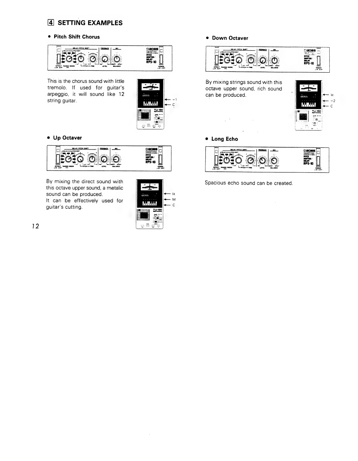
[4]
SETTING
EXAMPLES
e
Pitch
Shift
Chorus
DELAY
PITCH
SHE
(aro
6
Blo:
©
=
BANDA
woo
0
©
This
is
the
chorus
sound
with
little
tremolo.
If
used
for
guitar's
arpeggio,
it
will
sound
like
12
string
guitar.
ə
Up
Octaver
8
gangsa
|-
Ere
|
Aj
By
mixing
the
direct
sound
with
this
octave
upper
sound,
a
metalic
sound
can
be
produced.
It
can
be
effectively
used
for
guitar's
cutting.
+
fit
+
M
—
C
e
Down
Octaver
[ESI
6
Blolo:
E
|
ane
ERAT
PTC
BOY
nmo
mex
G
RANGE
MODE
am
aos
By
mixing
strings
sound
with
this
octave
upper
sound,
rich
sound
can
be
produced.
è
Long
Echo
LOUTH
Some
BEREE
erect
RANGE
MODE
Laren
band
FNE
lolo
Spacious
echo
sound
can
be
created.
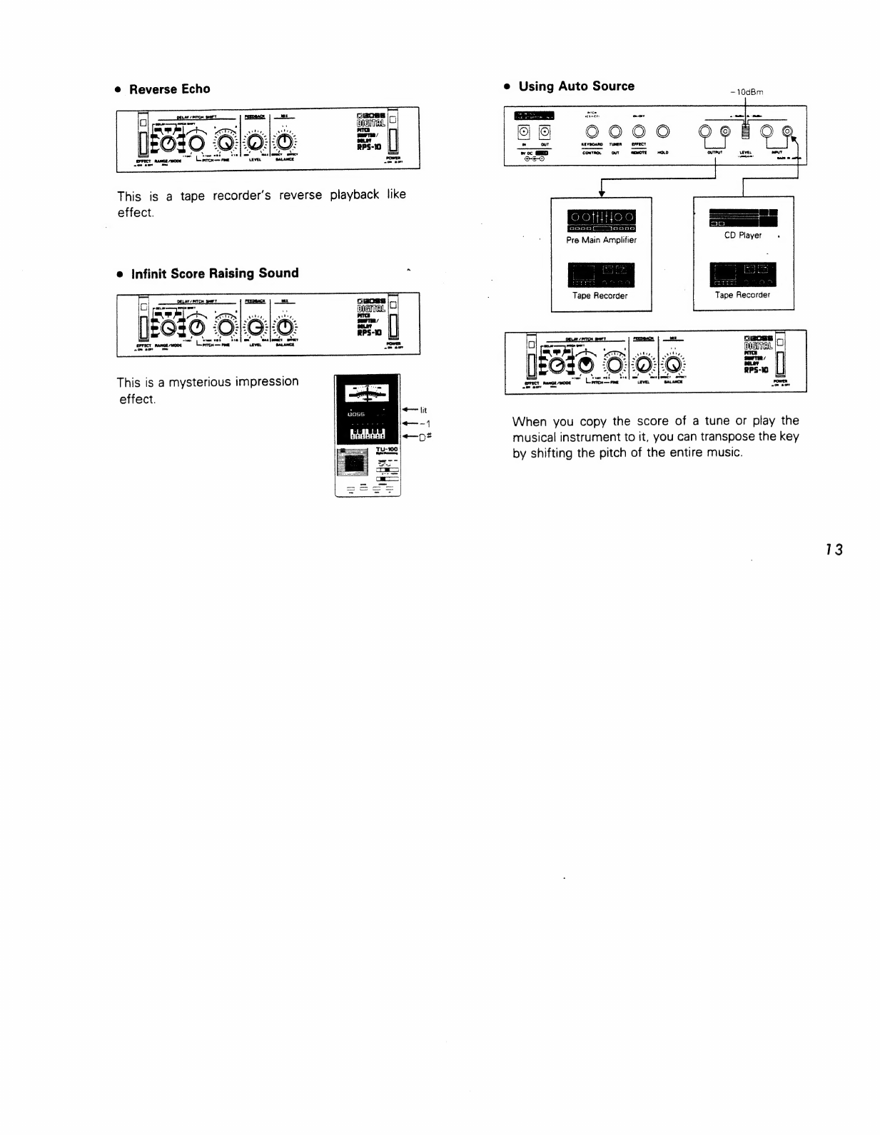
e
Reverse
Echo
This
is
a
tape
recorder’s
reverse
playback
like
effect.
e
Infinit
Score
Raising
Sound
i
AY
IPIN
jan
O:
ma
pi
og
tam
si
RANGE
MODE
re
This
is
a
mysterious
impression
effect.
+
lit
—-1
Seen
OO
as
e
Using
Auto
Source
OONO
tamak
Jeanna
Pre
Main
Amplifier
Tape
Recorder
When
you
copy
the
score
of
a
tune
or
play
the
musical
instrument
to
it,
you
can
transpose
the
key
by
shifting
the
pitch
of
the
entire
music.
13

14
[5]
IMPORTANT
NOTES
For
about
10
seconds
after
powered
up,
this
unit
does
not
function
because
of
the
muting
circuits.
Be
sure
to
use
the
AC
Adaptor
BOSS
PSA-120,
220
or
240
depending
on
the
line
voltage
system
in
your
country.
When
you
use
only
an
AC
adaptor
for
supplying
power
to
more
than
one
unit,
please
be
sure
that
the
total
current
draw
does
not
exceed
200mA.
(The
current
draw
of
each
unit
is
shown
on
its
rear
panel.)
When
the
unit
is
not
to
be
used
for
a
long
period
of
time,
disconnect
the
AC
adaptor
from
the
wall
socket.
Avoid
using
the
unit
in
extreme
heat
or
humidity
or
where
it
may
be
affected
by
dust.
When
you
use
only
Micro
Studio
Series
without
optional
Rack
Mount
Adaptor
“RAD-10",
please
attach
the
rubber
feet.
Refer
to
figure.
AC
ADAPTOR
BOSS
PSA-120,
220
OR
240
Be
sure
to
use
the
optional
BOSS
PSA
series.
Using
any
other
adaptor
wili
cause
trouble.
RACK
MOUNT
INSTALLATION
The
RPS-10
is
one
of
the
BOSS
Micro
Studio
Series,
and
by
using
the
Rack
Mount
Adaptor
RAD-10,
any
two
sets
of
the
Series
can
be
mounted
in
a
standard
19”
rack
(EIA-1U).
Remove
the
rubber
feet
(x4)
from
the
units,
then
attach
the
units
to
the
Rack
Mount
Adaptor
RAD-10,
then
mount
the
whole
set
in
the
rack.
i
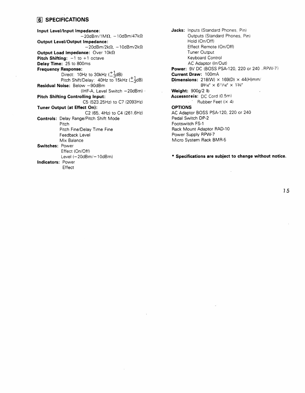
[6]
SPECIFICATIONS
Input
Level/input
Impedance:
—20dBm/1MQ,
—10dBm/47k2
Output
Level/Output
Impedance:
—20dBm/2kQ,
—10dBm/2k0.
Output
Load
Impedance:
Over
10kN
Pitch
Shifting:
—1
to
+1
octave
Delay
Time:
25
to
800ms
Frequency
Response:
Direct:
10Hz
to
30kHz
(£
lag)
Pitch
Shift/Delay:
40Hz
to
15kHz
(*4dB)
Residual
Noise:
Below
—90dBm
(IHF-A,
Level
Switch
—20dBm)
-
Pitch
Shifting
Controlling
Input:
C5
(523.25Hz)
to
C7
(2093Hz)
Tuner
Output
(at
Effect
On):
C2
(65,
4Hz)
to
C4
(261.6Hz)
Controls:
Delay
Range/Pitch
Shift
Mode
Pitch
Pitch
Fine/Delay
Time
Fine
Feedback
Lével
Mix
Balance
Switches:
Power
Effect
(On/Off)
Level
(~20dBm/—10dBm)
Indicators:
Power
Effect
Jacks:
Inputs
(Standard
Phones,
Pin)
Outputs
(Standard
Phones,
Pin)
Hold
(On/Off)
Effect
Remote
(On/Off)
Tuner
Output
Keyboard
Control
AC
Adaptor
(In/Out)
Power:
9V
DC
(BOSS
PSA-120,
220
or
240
.
RPW-7)
Current
Draw:
100mA
Dimensions:
218(W)
x
169(D)
x
44(H)mm/
l
86”
x
61e”
x
IYA!
Weight:
900g/2
Ib
Accessoreis:
DC
Cord
(0.5m)
Rubber
Feet
(x
4)
OPTIONS
AC
Adaptor
BOSS
PSA-120,
220
or
240
Pedal
Switch
DP-2
Footswitch
FS-1
Rack
Mount
Adaptor
RAD-10
Power
Supply
RPW-7
Micro
System
Rack
BMR-5
*
Specifications
are
subject
to
change
without
notice.
15
BOSS
Micro
Studio
Series
RCL-10
Compressor/Limiter
RBF-10
Flanger
RGE-10
Graphic
Equalizer
RPQ-10
Preamplifier/
Parametric
Equalizer
RPH-10
Phaser
RDD-10
Digital
Delay
RSD-10
Digital
Sampler/Dalay
RPS-10
Digital
Pitch
Shifter/
Delay
RPW-7
Power
Supply
Products
of
Roland
RPS-10
Instructions
Printed
in
Japan
Feb.
‘87
C-3
f=Roland”
10434
10434
TI
LIMA
Nan
Other manuals for RPS-10
1
Table of contents
Other BOSSCO Recording Equipment manuals

BOSSCO
BOSSCO ME-20B User manual

BOSSCO
BOSSCO RCL-10 User manual

BOSSCO
BOSSCO RSD-10 User manual

BOSSCO
BOSSCO VF-1 User manual

BOSSCO
BOSSCO ME-50 User manual

BOSSCO
BOSSCO GS-10 User manual

BOSSCO
BOSSCO BR-600 User manual

BOSSCO
BOSSCO SDE-3000EVH User manual

BOSSCO
BOSSCO GT-1000 User manual

BOSSCO
BOSSCO MICRO BR User manual

BOSSCO
BOSSCO BR-600 User manual

BOSSCO
BOSSCO RCE-10 User manual

BOSSCO
BOSSCO EQUALIZER User manual

BOSSCO
BOSSCO Dr.Rhythm DR-110 User manual

BOSSCO
BOSSCO GT-6B User manual

BOSSCO
BOSSCO VE-5 User manual

BOSSCO
BOSSCO BR-864 User manual

BOSSCO
BOSSCO Gigcaster 5 User guide

BOSSCO
BOSSCO RC-505 User manual

BOSSCO
BOSSCO BR-80 Instruction Manual


