Bosslan BOSST101 User manual

BOSSLAN BOSST101
IP PBX
User’s Guide V 1.01
Firmware V 1.00
January 2008

1
P
REFACE
Preface
ABOUT
THIS
MANUAL
This manual is designed for use with BOSST101 IP PBX.
Information in this document has been carefully checked for
accuracy; however, no guarantee is given to the correctness of
the contents. The information in this document is subject to
change without notice.
COPYRIGHT
© Copyright 2008
This document contains proprietary information protected by
copyright. All rights are reserved. No part of this manual may
be reproduced by any mechanical, electronic or other means,
in any form, without prior written permission of the
manufacturer.
TRADEMARKS
All trademarks and registered trademarks are the property of
their respective owners.
FCC
COMPLIANCE
This device complies with Part 15 of the FCC Rules. Operation
is subject to the following two conditions:
(1) This device may not cause harmful interference, and
(2) This device must accept any interference received,
including interference that may cause undesired operation.
Any changes or modifications not expressly approved by the
party responsible for compliance could void the authority to
operate equipment.
This equipment must be installed and operated in accordance
with provided instructions and the antenna(s) used for this
transmitter must be installed to provide a separation distance
of at least 20 cm from all persons and must not be co-located
or operating in conjunction with any other antenna or
transmitter. End-users and installers must be provided with
antenna installation instructions and transmitter operating
conditions for satisfying RF exposure compliance.

2
P
REFACE
FEDERAL
COMMUNICATIONS
COMISSION
(FCC)
STATEMENT
This equipment has been tested and found to comply with the
limits for a Class B digital device, pursuant to part 15 of the
FCC Rules. These limits are designed to provide reasonable
protection against harmful interference in a residential
installation. This equipment generates, uses and can radiate
radio frequency energy and, if not installed and used in
accordance with the instructions, may cause harmful
interference to radio communications. However, there is no
guarantee that interference will not occur in a particular
installation. If this equipment does cause harmful interference
to radio or television reception, which can be determined by
turning the equipment off and on, the user is encouraged to try
to correct the interference by one or more of the following
measures:
Reorient or relocate the receiving antenna.
Increase the separation between the equipment and the
receiver.
Connect the equipment to an outlet on a circuit different from
that to which the receiver is connected.
Consult the dealer or an experienced radio/TV technician for
help.
This equipment conforms with the USA technical criteria in
PART 68 TIA/EIA-968-A and AP15B(D.O.C.).
INDUSTRY CANADA CS-03 PART 1
The Industry Canada label identifies certified equipment. This
certification means that the equipment meets certain
telecommunications network protective, operational and safety
requirements as prescribed in the appropriate Terminal
Equipment Technical Requirements documents. The
Department does not guarantee the equipment will operate to
the user's satisfaction.
Before installing this equipment, user should ensure that it is
permissible to be connected to the facilities of the local
telecommunications company. The equipment must also be
installed using an acceptable method of connection. The
customer should be aware that compliance with the above
conditions may not prevent degradation of service in some
situations.

3
P
REFACE
Repairs to certified equipment should be coordinated by a
representative designated by the supplier. Any repairs or
alterations made by the user to this equipment, or equipment
malfunctions, may give the telecommunications company
cause to request the user to disconnect the equipment.
Users should ensure for their own protection that the electrical
ground connections of the power utility, telephone lines, and
internal metallic water pipe system, if present, are connected
together. This precaution may be particularly important in rural
areas.
Users should not attempt to make electrical ground
connections themselves, but should contact the appropriate
electric inspection authority, or electrician, as appropriate.
CE
COMPLIANCE
This product complies with the following standard of the
Directive 1999/5/EC of the European Parliament and of the
Council. of 9 March 1999 on Radio Equipment and
Telecommunications Terminal Equipment and the mutual
recognition of their conformity
Table 1: CE of Conformity
Safety EMC
TBR21 EN55022
EN60950-1 EN55024
ETL SAFETY
This product bears the ETL Listed Mark and has been tested
by Intertek. It meets the minimum requirements of U.S. or
Canadian electrical safety standards.

4
C
ONTENTS
Contents
Preface
........................................................
1
Introducing
BOSSLAN
BOSST101
IP
PBX
Package
Contents
.......................................
7
BOSST101
Overview
..................................
8
Front
Panel
....................................................
9
Rear
Panel.....................................................
10
Wall
Mounting
your
BOSST101
..................
11
Connecting
BOSST101
...............................
12
LAN
Connections...........................................
12
WAN
Connection
...........................................
13
PSTN
Connection
..........................................
14
Web
Configurator
Web
Configurator
Overview
........................
16
Accessing
BOSST101
.................................
16
Navigating
t
he
Web
Configurator
................
17
Navigation
Panel............................................
18
Quick
Con
f
igura
t
ion
.....................................
18
Status
..........................................................
19
System
Status................................................
19
Trunk
Status
..................................................
21
Handsets
Status
............................................
22
Users
.............................................................
23
Voice
Mail
Status
...........................................
25
Global
Settings
............................................
26
PBX
Global
Configuration..............................
26
SIP
Global
Configuration
...............................
29
Telephony
Services
.....................................
31
Voice
Settings................................................
31
Trunks............................................................
32
Auto
Attendants
.............................................
39
Users
List.......................................................
43
Handsets
.......................................................
46
Call
Restriction...............................................
50
Dial
Plan
........................................................
51

5
C
ONTENTS
Speed
Dial
.....................................................
53
Bridge
Calls
...................................................
55
Network
Services
........................................
57
WAN
Settings
................................................
57
LAN
Settings..................................................
60
NAT
Settings..................................................
61
Firewall
Settings
............................................
65
QoS
Settings
.................................................
67
Wireless
Settings
...........................................
69
System
Maintenance
...................................
71
Administrator..................................................
71
System
Time..................................................
73
Backup
and
Recovery....................................
73
Voice
Upload
.................................................
75
Firmware
Upgrade
.........................................
75
Tools
..............................................................
76
System
Restart
..............................................
76
Appendices
Appendix
A:
Troubleshooting
......................
78
Appendix
B:
Handset
Commands
...............
80
Index
........................................................
82

6
I
NTRODUCING BOSSLAN
BOSST101
Introducing
BOSSLAN
BOSST101 IP PBX
This chapter introduces the main features of your BOSSLAN
BOSST101.

7
I
NTRODUCING BOSSLAN
BOSST101
Package
Contents
When unpacking your BOSST101, ensure that you have the following
items. If any items are missing or broken please contact your dealer for a
replacement.
BOSST101
Manual CD x1 External Antenna x1
Phone
line
(26
AWG)
cable
used
for
RJ-11
connection.
RJ45 Ethernet Cable x1 RJ11 Telephone Cable x2
Power Supply x1 Power Cord x1
Wall Mounting Template x1 Screws with Screw Plugs x2
WARNING: Only use the supplied power adapter.

8
I
NTRODUCING BOSSLAN
BOSST101
BOSST101
Overview
BOSST101 is a highly configurable, high performance IP PBX providing
seamless Internet telephony across local and remote networks.
A Private Branch eXchange (PBX) is a telephone exchange that is
owned by a private business, as opposed to one owned by a
telephone company.
BOSST101 is also a router, Voice over IP (VoIP) gateway, and
bridge that uses Session Initiation Protocol (SIP) to initiate voice
calls within an office or even between remote locations without the
charges of the traditional Public Switched Telephone Network
(PSTN).
In addition to IP, VoIP uses the Real-Time Protocol (RTP) and Quality
of Service (QoS) to ensure calls are smooth and clear.
Use the Web Configurator to set up firewall, DMZ, NAT, LAN, WAN,
Bridge, and telephony services such as Auto Attendants, IP Phones,
analog phones, and even the route through which trunk calls are
made.
The following figure demonstrates BOSST101 applications.
INFO: BOSST101 comes with 2 FXO ports and 2 FXS ports. It
supports 4 VoIP channels and 12 concurrent calls.
9
I
NTRODUCING
BOSSLAN BOSST101
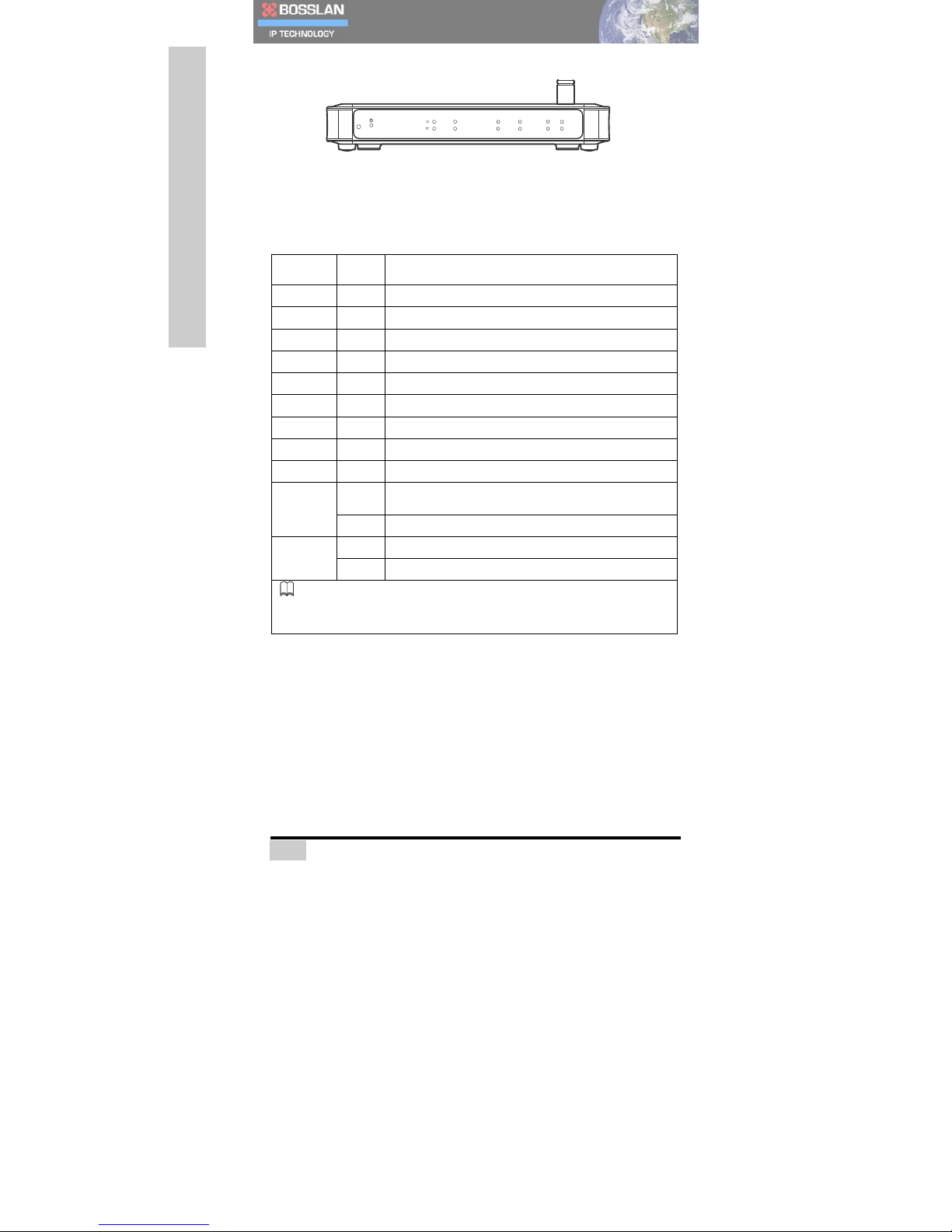
Front
Panel
RESET
1
LINE1
PBX
VoIP
WAN
LAN2
2
LINE2
INTERNET
Wi-Fi
LAN3
LAN1
The following table details how the front panel LEDs relate to the rear
panel connections.
Table
1:
Front
Panel
LEDs
LED State Description
Power On
System
Power
On
Phone
1
On
Analog
Extension
(FXS)
Line
in
use
Phone
2
On
Analog
Extension
(FXS)
Line
in
use
LINE
1On
PSTN
(FXO)
Line
in
use
LINE
2On
PSTN
(FXO)
Line
in
use
PBX On
Analog
Extension
Phone
Power
Ready
INTERNET
On
Internet
Status
Ready
VoIP On
VoIP
Trunk
Registration
Ready
Wi-Fi On
Wireless
Lan
is
enabled
WAN
On
Ethernet
link
is
synchronized
with
ADSL
modem,
cable
modem,
switch
and
hub.
Blinking
Transmitting/Receiving
Data.
LAN
1/2/3
On
Ethernet
link
is
synchronized
with
switch
and
hub.
Blinking
Transmitting/Receiving
Data.
INFO:
If
FXO
(1)
and
FXS
(2)
are
paired
for
power
failure
support.
In
the
event
of
power
loss,
all
incoming
calls
from
FXO
(1)
are
routed
to
FXS
(2),
if
it
remains
active.

10
I
NTRODUCING
BOSSLAN BOSST101
NOTE: BOSST101 provides a RESET button on the front
panel to restore its factory default settings. To reset your
BOSST101, do the following:
1. Ensure your BOSST101 is powered on.
2. Use a thin tool, such as a paper clip, to press the RESET
button for three seconds.
3. Wait at least 10 seconds, then disconnect the DC power
cable to power off your BOSST101.
4. Restart the device again.
Rear
Panel
To minimize service downtime or disruption it is recommended that
you first configure BOSST101 before connecting your telephone
lines.
LAN
1
2
3
WAN
DC12V
LINE1
LINE2
1
2
POWER
The following table describes the rear panel connections.
Table
2:
Rear
Panel
Connections
Connection Description
3x
10/100
Mbps
LAN
Ports
Ethernet
switch
with
auto
MDIX
(Media
Dependent
Interface
Crossover).
1x
10/100
Mbps
WAN
Ports
Ethernet
NIC
(Network
Interface
Card)
with
auto
MDIX.
2x
PTSN
Telephone
Ports
PSTN
Trunk
(FXO)
2x
Analog
Telephone
Ports
M1/M2
Extension
(FXS)
Power
Adapter
12V
DC
To
prevent
risk
of
damaging
the
product,
only
use
the
supplied
12VDC
power
adapter.

11
I
NTRODUCING
BOSSLAN BOSST101
Wa
ll
Mounting
your
BOSST101
The BOSST101 chassis can stand-alone or be wall-mounted. It is
recommended that you install BOSST101 away from electrical products
that it may interfere with, and at an easy-to-reach location for making
connections and viewing the LEDs. It is also advised that you allow a few
centimeters around BOSST101 for proper ventilation.
To mount BOSST101 to a wall:
First place the mounting template over the part of the wall you wish to
install BOSST101.
1. Now mark the wall through the holes in the template.
2. Drill two sets of holes in to the wall.
3. Insert the supplied screw plugs, and then insert the mount-
ing screws leaving the screw heads sticking out (see Pack-
age Contents on page 7).
4. Mount BOSST101 on to the screwheads as shown in the
following picture.
W all M ounting Tem plate
W all M ounting Tem plate
MO
DEL:BOSST 101
RATING
:+12V
---,2A
FC
C
REG
.#
US:1YD
IS00B
BOSST101
MADE
IN
MA LAYSIA
BOSSLAN
CO
RPO
RATION

12
I
NTRODUCING
BOSSLAN BOSST101
The following graphic shows a correctly wall-mounted BOSST101
with the rear panel connections (see Rear Panel on page 10) at the
bottom, and the front panel LEDs at the top (see Front Panel on
page 9).
Connecti
ng BOSST101
LAN
Connections
BOSST101 is also a DHCP server, and provides a simple
network environment.
The BOSST101’s LAN ports are compatible with standard category 5
RJ45 ethernet cable. Once a connection is established, the LED
corresponding to that port illuminates see Front Panel LEDs on page
9.
Connect to the BOSST101 LAN via the following:
• IP Phone: BOSST101 supports SIP-based IP phones such as
the AQ-101 desktop phone. Use a switch/hub to extend your LAN
ports to connect more phones.
• PC Connection: Enables access to the BOSST101 Web
Configurator.
INFO: Once there are PCs connected to BOSST101,
bandwidth should be well managed to ensure voice quality
over IP.
13
I
NTRODUCING
BOSSLAN BOSST101
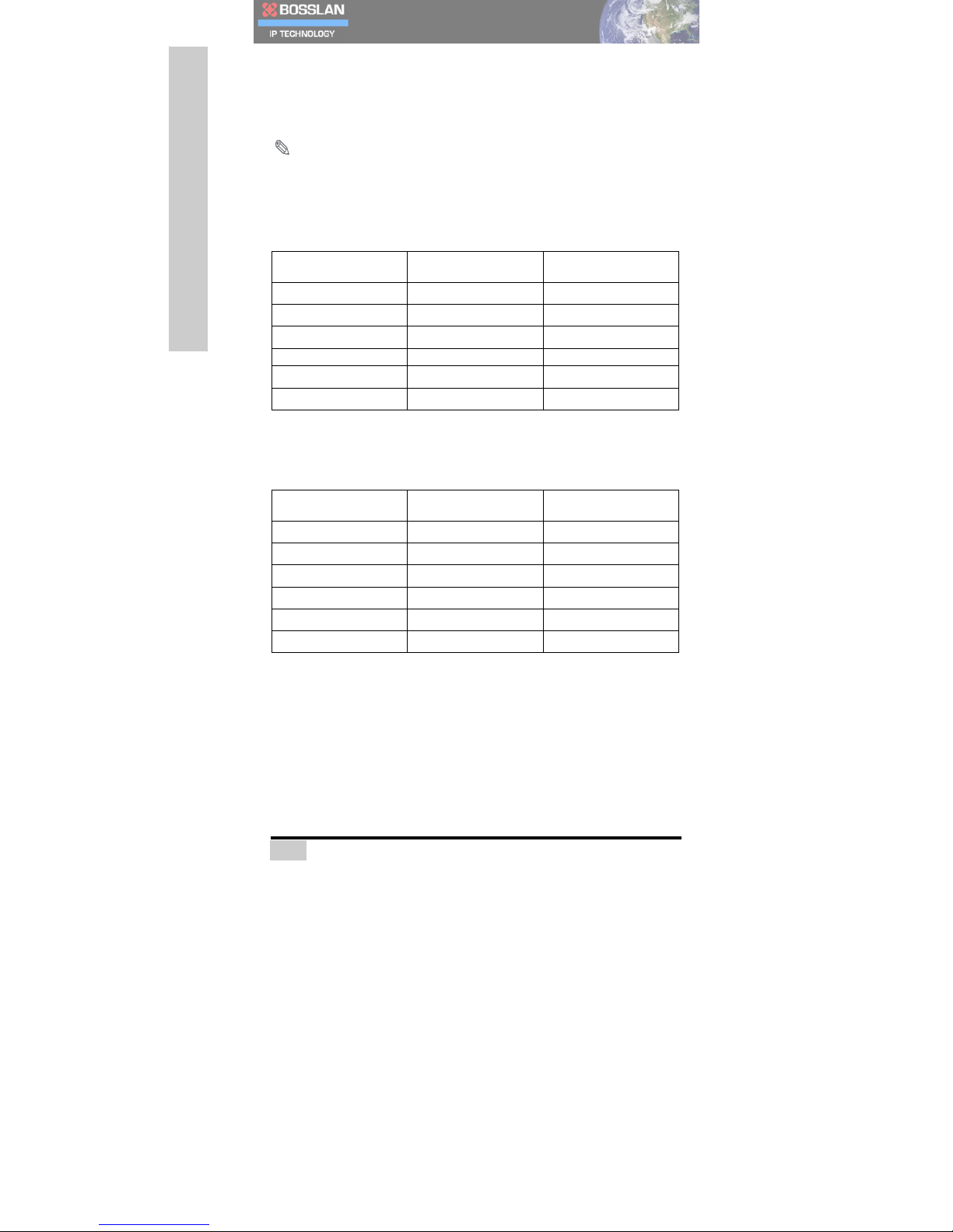
WAN
Connection
The BOSST101 WAN port can be configured for use with PPPoE,
Static IP, or DHCP to access the Internet.
NOTE
:
When selecting a codec, ensure the configuration
corresponds to the bandwidth provided by your ISP.
The following table lists configurations and their required bandwidths
for an unsecured network.
Table
3:
Connection
Bandwidth
(Unsecured)
Packet Size/msec G711 (kbit/s) G729 (kbit/s)
10
105 50
20
84 29
30
77 22
40
73 18
50
71 16
60
70 15
The following table lists codec configurations and their required
bandwidths for an encrypted network (e.g. when VPN is used).
Table
4:
Connection
Bandwidth
(Encrypted)
Packet Size/msec G711 (kbit/s) G729 (kbit/s)
10
146 92
20
105 49
30
91 35
40
84 29
50
80 25
60
77 22
The BOSST101’s WAN port is compatible with standard category 5 RJ45
ethernet cable. Once a connection is established, the LED
corresponding to that port illuminates see Front Panel LEDs on page
9.
Connect BOSST101 to your WAN via the following:
• Connecting a Modem: If PPPoE or Static IP assigned
by your ISP is selected as the WAN interface Protocol,
please connect your modem to the WAN connection of
BOSST101 with a Category 5 cable. For details on WAN
configuration, see WAN Settings on page 57.

14
I
NTRODUCING
BOSSLAN BOSST101
• Connecting to a Switch/Hub: You can easily connect
BOSST101 to an existing local network with standard Category
5 ethernet cable. BOSST101 can obtain an IP automatically
from your local DHCP server or you can assign a static IP,
which is assigned
by network administrator (see WAN Settings on page 57). In
both scenarios, please make sure existing network is well man-
aged as Voice quality depends on bandwidth availability.
PSTN
Connection
• Connecting BOSST101 to your Landline: You can connect
your PSTN line(s) from the wall jack(s) to your BOSST101. Take
note of which telephone line is connected to which BOSST101
FXO line jack as you will need it for configuration.
• Connecting Analog Extensions: You can connect analog
devices such as telephones, fax machines, or answering
machines to your BOSST101. Connect your analog extensions
to the Phone ports (Phone 1 and Phone 2) on the rear of your
BOSST101.
WARNING: To reduce the risk of fire, use only No. 26 AWG or
larger telecommunication line cord.

15
W
EB
C
ONFIGURATOR
Web Configurator
This chapter details how to access and configure the screens of
BOSST101
Web Configurator.

16
W
EB
C
ONFIGURATOR
We
b
Configurator
Overv
i
ew
The BOSST101 Web Configurator is an embedded html-based interface
providing direct access through an Internet browser to system
configuration and settings.
Accessing
BOSST101
1. Connect your PC’s LAN port to the BOSST101 LAN port (see
LAN Connections on page 12).
2. Configure your PC for use with the TCP/IP protocol, and
enable DHCP IP addressing to automatically obtain an IP
address from BOSST101.
3. Open a web browser and type http://192.168.100.1:8000 as the
URL (Internet address).
4. Type in the username admin and password 1234. Now click
Login.
You are now ready to begin configuring your BOSST101.
NOTE
:
Please note that some settings only take effect after
rebooting BOSST101.

17
W
EB
C
ONFIGURATOR
Navigating
the
We
b
Configurator
This manual uses screenshots taken from BOSST101. BOSST101
screens may
vary slightly with the increased number of ports; setup however,
remains the same.
The following figure shows the first screen displayed after login.
INFO: There is a special assistant on the web configurator.
Check the Help box (highlighted on the top left) to view
information for each setting and their examples.

18
W
EB
C
ONFIGURATOR
Navigation
Panel
After login, use the menu system on the navigation panel to configure
your BOSST101. Click on a category to expand the panel to view
submenus. Click an expanded category to roll up that menu and hide
the submenus.
Quick
Configuration
In order to begin using your BOSST101 as soon as possible, please see
the
following steps for minimal configuration.
Table
1:
Quick
Configuration
Steps Reference
1.
Connect
the
hardware
Connecting
BOSST101,
page
12
2.
Configure
WAN
settings WAN
Settings,
page
57
3.
Create
Users
Users
List,
page
43
4.
Assign
handsets
to
users Handsets,
page
46
5.
Set
up
trunks
to
allow
incoming
and
outgoing
calls. Trunks,
page
32
6.
Define
Auto
Attendants
Auto
Attendants,
page
40
For more details of all other settings to adapt BOSST101 to your
environment, please see Telephony Services, Network Services and
System Maintenance.

19
W
EB
C
ONFIGURATOR
BOSST101
Stat
u
s
The BOSST101 status screens are for your reference only and cannot be
configured.
System
Status
The system status screen displays internal and connection data about
your BOSST101. It also lists the office hours of a working week and
includes non-working days
The following table describes the fields in the System Status screen.
Table
2:
System
Status
Menu
Field Description
Hardware
Information
Serial
Number This
field
displays
the
serial
number
of
your
BOSST101.
Firmware
Version This
field
displays
the
current
version
of
the
software
embedded
in
your
BOSST101.
Table of contents
Popular PBX manuals by other brands


Nortel
Nortel Meridian 1 PC Console Interface Unit Implementation guide

Well
Well mPBX-U110R installation guide

Panasonic
Panasonic KX-TDE100 Network guide

Panasonic
Panasonic KX-NS300CN Pc programming manual

SpectraLink
SpectraLink Link 3000 Installation and setup

TransTel Communications
TransTel Communications IP8100C user manual