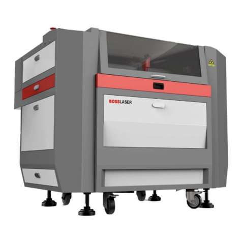
BOSSLASER LS Series User manual

BOSSSER
SERIES
Q
UI
CK
START
G
UI
D
E

Quick Start Guide for
LS Series Machines
608 Trestle Point
Sanford, FL 32771
Phone 888-652-1555 • Fax 407-878-0837
www.BOSSLASER.com

Warranty Disclaimer
Thank you for your interest in the products and
services of Boss Laser, LLC.
This Limited Warranty applies to the laser machines and parts purchased from Boss
Laser, LLC.
This Limited Warranty covers any defects in material or workmanship under
normal use during the Warranty Period. This does NOT include labor and/or
on-site Tech. Support.
During the Warranty Period, Boss Laser, LLC will repair or replace, at no charge,
products or parts of a product that proves defective because of improper material
or workmanship, under normal use and maintenance.
Boss Laser, LLC will repair the product at no charge, using new replacement parts.
The Warranty Period for laser machine parts purchased from Boss Laser, LLC is one
year from the day of arrival (Exception of Lens & Mirrors, which are 30 days from
arrival).
A replacement part assumes the remaining warranty of the original part
(Exception of Lens & Mirrors, which are 30 days from arrival).
This Limited Warranty does not cover any problem that is caused by:
•Conditions, malfunctions or damage not resulting from defects in material
or workmanship (ex. modifications done to the machine)
Any modifications without written consent from Tech. Support,
will void your machine's warranty.
To obtain warranty service, you must first contact Tech. Support
(888.652.1555 or [email protected]) to determine the
problem and the most appropriate solution for you.

Table of Contents
Unpacking & Removing Accessories .................................... 1
Setting Up Laser for the First Time .......................................... 2
Exhaust Blower Hook-Up for LS-1416s & 1420s .................... 3
Air Assist Hook-Up w/ Pump ................................................. 5
Exhaust Blower Hook-Up for Ls-1630s & Up ........................ 4
Air Assist Hook-Up w/ Compressor ....................................... 6
Water Pump Hook-Up ........................................................... 7
Water Chiller (CW-3000 & CW-5000) Hook-Up .................... 8
Toolbox Contents .................................................................. 9
HELLO WORLD Walkthrough .............................................. 11

Unpacking & Removing Accessories
Once the delivery truck leaves, your new laser will be inside the large wooden
box like the one shown above. Make sure you are ready with necessary tools and
plenty of room for laying out the parts and accessories of your new laser.
Our crates are usually banded to a wooden pallet for safe shipping. Take a few
minutes and check for any damage to the bands and crate. If you see any damage such
as pierced or broken plywood take a picture before removing bands. If it looks
smashed or opened take more pictures. The machine is insured for its value and may
be damaged if the crate is badly damaged. Trucking companies are usually excellent at
covering damage if any damage occurred during shipping. So document any issues and
contact our shipping department via email at [email protected].
Now chances are no damage exist and you are ready to open the crate. Cut any
bands. Then carefully remove the top lid. All of our crates will be secured by 2” staples.
Carefully, pry out the staples around the crate. Be careful not to use any part of the
plywood interior for a focal point on the pry bar. Stay on the outside framing to ensure
not piercing plywood and damaging machine.
Once the top lid is off, look inside and find any loose boxes containing
accessories. Remove any boxes that may fall when sides are removed. Remove front
panel and then two side panels, then the back panel. Save the crate panels in the
event you ever need to move the machine again.
QUICK START GUIDE FOR LS MACHINES
Document Number: 855-915
Revision: 001 Revision Date: 12/11/2019
BOSSLASER - PAGE 1 of 18

Setting Up the Laser for the First Time
Make sure to remove any foam material from inside of cabinet.
Remove any plastic zip-ties used for securing laser head from moving on the X
and Y Axis during shipping. Depending on what options purchased with your
laser, the crate will have several boxes outside of the laser cabinet. You
should see the common items listed below and possibly some additional
accessories:
6" Exhaust Blower (For 1630s & Up)
4" Exhaust Blower (For 1416s & 1420s)
Air Compressor w/ 6mm fitting (included)
Water Pump
CW-3000 (left) & CW-5000 (right) Water Chiller
QUICK START GUIDE FOR LS MACHINES
Document Number: 855-915
Revision: 001 Revision Date: 12/11/2019
BOSSLASER - PAGE 2 of 18

Exhaust Blower Hook-Up for LS-1416s & 1420s
4" flange w/ three hose clamps Exhaust
Port
Exhaust Port
w/ 4" flange
4" Exhaust Tubing
Installed w/ hose clamp
Connect exhaust tubing from machine to
intake. Then connect exhaust tubing to
the exhaust port to your preference.
350 CFM Blower: 7 A / 640 W (at start-up), 2.6 A / 310 W (at idle)
Exhaust Power Requirement
QUICK START GUIDE FOR LS MACHINES
Document Number: 855-915
Revision: 001 Revision Date: 12/11/2019
BOSSLASER - PAGE 3 of 18

Exhaust Blower Hook-Up for LS-1630s & Up
Three hose clamps (in toolbox) Exhaust Port located at
the bottom (ex. LS-3655 shown)
6" Exhaust tubing installed
w/ hose clamp
Connect exhaust tubing from machine to
intake. Then connect exhaust tubing to
the exhaust port to your preference.
500 CFM Blower: 20 A / 1800 W (at start-up), 5.8 A / 667 W (at idle)
Exhaust Power Requirement
QUICK START GUIDE FOR LS MACHINES
Document Number: 855-915
Revision: 001 Revision Date: 12/11/2019
BOSSLASER - PAGE 4 of 18

Air Assist Hook-Up w/ Pump
Gold Air Pump w/ 6mm hosing & fitting Location of installing fitting
Fitting installed w/ 6mm hosing 6mm hosing hook-up to machine
QUICK START GUIDE FOR LS MACHINES
Document Number: 855-915
Revision: 001 Revision Date: 12/11/2019
BOSSLASER - PAGE 5 of 18

Air Assist Hook-Up w/ Compressor
Air Compressor w/ 6mm hosing & fitting Location of installing fitting
Removing original fitting for 6mm fitting
using a 19mm wrench
Installing 6mm fitting using a
14mm wrench
Installed 6mm fitting onto compressor 6mm hosing hook-up to machine
QUICK START GUIDE FOR LS MACHINES
Document Number: 855-915
Revision: 001 Revision Date: 12/11/2019
BOSSLASER - PAGE 6 of 18

Water Pump Hook-Up
Water pump w/ fitting & hosing Installing
Suction cups
Installing fitting for
silicone tubing
Installing silicone tubing
from water pump to
Water In machine
Water pump in 5
gallon bucket
Using the 2nd silicone
tubing, connect it
from Water Out to 5
gallon bucket
Fill up the 5 gallon bucket to where the water pump is completely submerge
in Distilled Water and cover it with a bucket lid (to keep any debris away)
Note: It is recommended to keep the water temperature between
18 - 25 degrees Celsius (64 - 77 degrees Fahrenheit)
QUICK START GUIDE FOR LS MACHINES
Document Number: 855-915
Revision: 001 Revision Date: 12/11/2019
BOSSLASER - PAGE 7 of 18

Water Chiller (CW-3000 & CW-5000) Hook-Up
Water Chiller w/ silicone tubing,
chiller signal cable, and power cord
Outlet from the water chiller to
Water In of the machine
Inlet from the water chiller to
Water Out of the machine Chiller Signal Cable Outlet
Water Chiller fully installed
Fill the water chiller only using
Distilled Water. Try to keep the
temperature between 18 - 25
degrees Celsius for the CW-3000.
The CW-5000 is already set by
default from the factory to be
within 18 - 25 degrees Celsius.
QUICK START GUIDE FOR LS MACHINES
Document Number: 855-915
Revision: 001 Revision Date: 12/11/2019
BOSSLASER - PAGE 8 of 18

Toolbox Contents
1. Exhaust Hose Clamps (3 count)
2. 6mm Nylon High Pressure Hosing
3. Resistor w/ Voltage & GND Wiring Clamps
4. Air Nozzle Regulator
5. High Precision Proximity Switch
6. Water Chiller Bypass Signal
7. 250V/20A Fuses (2 count)
8. Universal Machine Door Keys (3 sets of 2's)
9. Processing Test File Sample
10. Phillips Head Screwdriver
11.500 MB Flashdrive
12. Ignition Keys (1 set of 2's)
13. A Set of Allen Keys
14. Focal Guide
15. 6-Pin Terminal w/ Wire Loop
16. Mirror Removal Tool
17. Lens Removal Tool
18. Power Cord
19. Nozzle Removal Tool
NOTE: The circled contents are used for testing purposes (assisted w/ Technical Support, if needed).
For LS-1416/LS-1420 machines, a 4" flange is included in the toolbox.
QUICK START GUIDE FOR LS MACHINES
Document Number: 855-915
Revision: 001 Revision Date: 12/11/2019
BOSSLASER - PAGE 9 of 18

Toolbox Contents (cont.)
Different Size Nozzles for Specific Size Lens
1. For 2" lens
a. Recommended lens for engraving & cutting
2. For 2.5" lens
a. Leaning more towards cutting capacity than engraving
3. For 4" lens
a. Ideally for cutting than engraving material
In the toolbox, there will be 3 different size nozzles provided for you. Each nozzle
will correlated with a specific size lens (as described below):
QUICK START GUIDE FOR LS MACHINES
Document Number: 855-915
Revision: 001 Revision Date: 12/11/2019
BOSSLASER - PAGE 10 of 18

,>>KtKZ>tĂůŬƚŚƌŽƵŐŚ
Now launch the LightBurn software:
Click on the Text icon indicated by the red arrow w/ the red square around it:
QUICK START GUIDE FOR LS MACHINES
Document Number: 855-915
Revision: 001 Revision Date: 12/11/2019
BOSSLASER - PAGE 11 of 18

Once you have selected Text, click anywhere on the grid space and a text cursor will
appear (as shown below):
For this exercise, type "Hello World" in the text box (as shown below):
QUICK START GUIDE FOR LS MACHINES
Document Number: 855-915
Revision: 001 Revision Date: 12/11/2019
BOSSLASER - PAGE 12 of 18

The next step is to set the Speed and Power for the image. Located on the top right side
of the LightBurn software, you'll find the Layer Options (as shown below):
QUICK START GUIDE FOR LS MACHINES
Document Number: 855-915
Revision: 001 Revision Date: 12/11/2019
BOSSLASER - PAGE 13 of 18

Double click on the Layer Color. The Layer Parameter window, shown below, should appear:
•Mode: Make sure this is set to Fill
•Power (%): For this exercise, we are going to use 25% (for Min. & Max.)
•Speed (mm/sec): Set this to 300. Maximum Speed is limited to 500.
•Line Interval (mm): Set this to 0.065. Recommended range = 0.065 - 0.1
After those changes have been made, click on the OK button.
QUICK START GUIDE FOR LS MACHINES
Document Number: 855-915
Revision: 001 Revision Date: 12/11/2019
BOSSLASER - PAGE 14 of 18

The next step is to now send this file to the machine. Make sure you have the Black USB Cable
connected to the PC from the machine and that the machine is ON.
Now locate the Send button which is below the Cuts Window (on the right side of the
software):
Once you clicked on the Send button, the window shown below will appear. You can add a name to your file
(for this exercise, we named it HELLO). Then click OK to send this file to the machine.
QUICK START GUIDE FOR LS MACHINES
Document Number: 855-915
Revision: 001 Revision Date: 12/11/2019
BOSSLASER - PAGE 15 of 18

WƌĞƐƐŝŶŐƚŚĞFileďƵƚƚŽŶŝůůƵƐƚƌĂƚĞƐĂƐƐŚŽǁŶ
KŶƚŚĞ>ƐĐƌĞĞŶƉƌĞƐƐƚŚĞFileďƵƚƚŽŶ>ŽĐĂƚĞĚďLJƚŚĞƌĞĚďŽdžƚŚĞHelloĨŝůĞŝƐŚŝŐŚůŝŐŚƚĞĚ
ĂŶĚĂƉƌĞǀŝĞǁŽĨƚŚĞŝŵĂŐĞŝƐŝůůƵƐƚƌĂƚĞĚĂƚƚŚĞďŽƚƚŽŵůĞĨƚͲŚĂŶĚĐŽƌŶĞƌŽĨƚŚĞƐĐƌĞĞŶtŝƚŚƚŚĞHelloĨŝůĞ
ƐƚŝůůƐĞůĞĐƚĞĚƉƌĞƐƐEnterĂŶĚǁŝůůďĞƌĞƚƵƌŶƚŽƚŚĞŵĂŝŶƐĐƌĞĞŶǁŝƚŚƚŚĞΗ,ĞůůŽtŽƌůĚΗƚĞdžƚ (as shown
below)
WƌĞǀŝĞǁŽĨƚŚĞΗ,ĞůůŽtŽƌůĚΗƚĞdžƚǁŝƚŚŝƚƐůĂƐĞƌƐĞƚƚŝŶŐƐůŽĐĂƚĞĚŽŶƚŚĞ
ďŽƚƚŽŵůĞĨƚͲŚĂŶĚĐŽƌŶĞƌŽĨƚŚĞƐĐƌĞĞŶ
QUICK START GUIDE FOR LS MACHINES
Document Number: 855-915
Revision: 001 Revision Date: 12/11/2019
BOSSLASER - PAGE 16 of 18
Other manuals for LS Series
2
This manual suits for next models
3
Table of contents
Other BOSSLASER Industrial Equipment manuals
