Somex MAX30B Technical manual

Date de création : 19/11/07
Indice de révision : C 1
MAX30B

Date de création : 19/11/07
Indice de révision : C 2
Sommaire
Contents
Inhaltsverzeichnis
Sommaire
Contents
Inhaltsverzeichnis
Sommaire
Contents
Inhaltsverzeichnis
Sommaire
Contents
Inhaltsverzeichnis
Sommaire
1. Indication de sécurité
1.1 Instructions générales de
sécurité
1.2 Applications autorisées
1.3 Applications non autorisées
1.4 Déclaration du fabricant
1.5 Glossaire des symboles
2. Mise en service
2.1 Montage
2.2 Asservissement
2.3 Données techniques
2.4 Conditions d’exploitation
3. Utilisation
3.1 Exploitation
3.2 Réglages
4. Maintenance
4.1 Maintenance préventive
4.2 Réparation
4.3 Prestations de garanties
4.4 Stockage
4.5 Elimination / Compatibilité
environnementale
Contents
1. Notes on safety
1.1 General notes on safety
1.2 Intentional use of unit
1.3 Incorrect use
1.4 Manufacturer’s declaration
1.5 Symbol legend
2. Start up
2.1 Installation
2.2 Electrical connections
2.3 Technical specifications
2.4 Operating requirement
3. Handling
3.1 Operation
3.2 Adjustments
4. Maintenance
4.1 Preventive maintenance
4.2 Repair
4.3 Warranty
4.4 Storage
4.5 Safe Disposal
Inhaltsverzeichnis
1. Sicherheitshinweise
1.1 Allgemeiner
sicherheitstechnischer
Hinweis
1.2 Bestimmungsgemäße
Verwendung
1.3 Nicht bestimmungsgemäße
Verwendung
1.4 Herstellererklärung
1.5 Symbolerklärung
2. Inbetriebnahme
2.1 Montage
2.2 Ansteuerung
2.3 Technische Daten
2.4 Betriebsbedingungen
3. Handhabung
3.1 Betrieb
3.2 Stellung
4. Instandhaltung
4.1 Vorbeugende
Instandhaltung
4.2 Reparatur
4.3 Garantieleistung
4.4 Lagerung
4.5 Entsorgung /
Umweltverträglichkeit

Date de création : 19/11/07
Indice de révision : C 3
1. Indication de sécurité
1. Notes on safety
1. Sicherheitshinweise
2. Mise en service
2. Start up
2. Inbetriebnahme
3. Utilisation
3. Handling
3. Handhabung
4. Maintenance
4. Maintenance
4. Instandhaltung
1. Indication de sécurité
1.1 Instructions générales de
sécurité
C’est la structure principale,
composée d’un bâti et d’une
protection périphérique, qui
assurera dans tous les cas la
protection de sécurité de nos
unités d’usinage et de
translation avec leurs
accessoires, équipements et
outillages.
Tous les opérateurs sur la
machine de production doivent
être équipés personnellement
de matériels de sécurité tels
que : lunettes, gants,
chaussures de sécurité, habits
selon prescription, etc.
La mise en œuvre et les
réglages de nos composants et
de la machine ne peuvent être
assurés que par du personnel
formé et habilité à cet effet. Des
prescriptions clairement
définies doivent être respectées
par l’opérateur, afin que tous
les aspects de la sécurité
soient assurés avec
compétence.
Lors des opérations de
montage et de réglage,
descendez le sectionneur
principale. Assurez-vous contre
un enclenchement intempestif
(par exemple, avec un
cadenas). Maintenez les
équipements et installations de
sécurité en fonction et en place.
N’enlevez pas les copeaux
avec les mains, utilisez les
crochets appropriés.
1. Notes on safety
1.1 General notes on safety
A machine design and structure
consisting of a solid machine
base and an all around
safety personal enclosure is
required to ensure safety and
protection of our machining
units, slides, accessories and
tools against damage!
All service and maintenance
work on a production machine
must be carried out wearing
personal safety items such as,
safety shoes, glasses and
gloves including appropriate
clothing.
All machine including our
components may only be
serviced by qualified and
authorized personal. Clearly
defined instructions must be in
place and observed
by operators to help ensure that
all safety related measures are
being followed properly.
During installation and at any
other time, when servicing the
machine, make sure that the
main power switch is turned
OFF. Safeguard against
unintentional machine start-up.
Install a pad lock. Make sure
that all machine safety devices
are in place and working.
Do not remove metal chips by
hand. Use appropriate tools.
1. Sicherheitshinweise
1.1 Allgemeiner
sicherheitstechnischer Hinweis
Die Struktur generell
ausgestattet mit einem
Unterbau und einem
Schutzgehäuse gewährleistet
in allen Fällen die Sicherheit für
unsere Bearbeitungseinheiten
und Schlitten, ausgerüstet mit
unseren Aufbaukomponenten,
Zubehör und Werkzeuge
Alle Arbeiten an dieser
Bearbeitungsmaschine dürfen
nur mit persönlicher
Schutzausrüstung
(Sicherheitsschuhe,
Schutzbrille,
Schutzhandschuhe, geeignete
Schutzkleidung, usw)
durchgeführt werden.
Die Maschine darf nur von
ausgebildetem und
autorisiertem
Bedienungspersonal bedient
werden. Die Zuständigkeiten
bei der Bedienung der
Maschine müssen klar
festgelegt und eingehalten
werden, damit unter dem
Aspekt der Sicherheit keine
unklaren Kompetenzen
auftreten
Schalten sie den
Maschinenhauptschalter aus,
wenn Sie Wartung oder
Instandsetzungsarbeiten
durchführen und sichern sie ihn
gegen unbeabsichtigtes
Einschalten (z.B.
Schlossanbringen). Lassen Sie
die Sicherheitseinrichtungen an
ihrem Ort und in ihrer Funktion.
1.2 Applications autorisées
Les unités d’usinage avec leurs
accessoires et équipements,
sont des composants pour
l’automatisation exclusivement
destinés à être intégrés dans
une machine de production.
1.2 Intentional use of unit
The units machining with their
accessories and equipment,
are components for the
automation solely intended to
be integrated into a production
machine.
1.2 Bestimmungsgemäße
Verwendung
Die Bearbeitungseinheit mit
Zubehör und Ausrüstung ist
speziell geeignet für den
Anlagenbau.

Date de création : 19/11/07
Indice de révision : C 4
1. Indication de sécurité
1. Notes on safety
1. Sicherheitshinweise
2. Mise en service
2. Start up
2. Inbetriebnahme
3. Utilisation
3. Handling
3. Handhabung
4. Maintenance
4. Maintenance
4. Instandhaltung
1.3 Applications non autorisées
L’utilisation d’outils d’abrasion.
L’utilisation excessive de
lubrifiant ou de l’unité dans un
environnement par brouillard
d’huile.
1.3 Incorrect use
Use of abrasive tools.
Excessive flood coolant or
coolant mist environment.
1.3 Nicht bestimmungsgemäße
Verwendung
Der Einsatz von Werkzeugen
Abrieb.
Die Verwendung von
übermäßigen Mengen an
Kühlschmiermittel, oder der
Einsatz der Einheit in einer
ölnebelgetränkten Umgebung.
1.4 Déclaration du fabricant
Le fabricant ou son mandataire
établit dans la communauté ou
celui mettant en service
SOMEX S.A.S
Z.A de la Passerelle
68190 ENSISHEIM
déclare par la présente que les
composants de la machine
décrite ci-après :
Type : MAX30B
Numéro de série:
Voir chapitre 4.1
ne doit être mise en service
que pour le montage dans une
machine ou dans le but
d’assemblage avec d’autres
machines ou parties de
machines et,
que leur mise en service est
proscrite avant qu’il ne soit
établi que la machine dans
laquelle elle doit être montée
est conforme aux ordonnances
des directives sur les machines
de la CE
Les normes harmonisées
suivantes ont été appliquées :
EN292,EN60204
F-Ensisheim
le 10 décembre 2006
E. Desmaizières
Directeur général
1.4 Manufacturer’s declaration
The manufacturer or his
designated and authorized local
agent or distributor of
SOMEX S.A.S
Z.A de la Passerelle
68190 ENSISHEIM
declares herewith, that the
described machining unit:
Type : MAX30B
Serial number:
See chapter 4.1
May only be sold and
distributed with the intension of
being integrated inside a
machine or being used with
other machining components to
meet a specific purpose.
Any start-up attempts must be
declined until all machine
relevant safety measures
according to
EU standards are being met.
Applicable EU standards are:
EN 292 and EN 60204
F-Ensishein
le 10 décembre 2006
E. Desmaizières
Managing Director
1.4 Herstellererklärung
Der Hersteller oder sein in der
Gemeinschaft niedergelassner
Bevollmächtigter oder der
Inderkehrbringer
SOMEX S.A.S
Z.A de la Passerelle
68190 ENSISHEIM
erklärt hiermit, dass die
nachstehend beschriebene
neue Maschinenkomponente:
Type: MAX30B
Serien Nr. :
Siehe Kapitel 4.1
nur zum Zwecke des Einbaus
in einer Maschine oder zum
Zweck des Zusammenfügens
mit anderen Maschinen in
Verkehr gebracht wird und
dass deren Inbetriebnahme so
lange untersagt ist, bis
festgestellt wurde, dass die
Maschine , in die sie eingebaut
werden soll, den
Bestimmungen der EG-
Richtlinie Maschinen entspricht
Folgende harmonisierte
Normen wurden angewandt:
EN 292, EN 60204
F-Ensisheim
den 10 Dezember 2006
E. Desmaizières
Geschäftsleiter

Date de création : 19/11/07
Indice de révision : C 5
1. Indication de sécurité
1. Notes on safety
1. Sicherheitshinweise
2. Mise en service
2. Start up
2. Inbetriebnahme
3. Utilisation
3. Handling
3. Handhabung
4. Maintenance
4. Maintenance
4. Instandhaltung
1.5 Glossaire des symboles
Attention! à lire
impérativement !
Cette information est très
importante pour la garantie de
fonctionnement du produit. La
non observation peut entraîner
une défectuosité.
Indication relative à la sécurité /
Danger
Cette information est très
importante pour la garantie de
fonctionnement du produit. La
non observation peut nuire à la
sécurité de l’opérateur.
Information
Cette information sert à la
compréhension du
fonctionnement du produit. Par
cela, la pleine capacité de
fonctionnement du produit
pourra être exploitée.
Elimination
Elimination favorable à
l’environnement.
1.5 Symbol legend
Attention ! Make sure to read !
This information is very
important to ensure correct
operation of the product.
Failure to follow this information
can result in a product defect or
injury.
Note on safety/hazard
This information serves to
obtain safe operation. Failure to
follow this information may
compromise the operator’s
safety.
Information
This information serves for the
better understanding of product
function and operation.
Following these
recommendations will allow to
optimise product performance
and help to extend life.
Disposal
Friendly to the environment
disposal.
1.5 Symbolerklärung
Achtung ! Unbedingt lesen !
Diese Information ist sehr
wichtig für die
Funktionsgewährleistung des
Produktes. Bei Nichtbeachten
kann ein Defekt die Folge sein.
Sicherheitshinweis / Gefahren
Diese Information dient zum
Erlangen eines sicheren
Betriebes. Bei Nichtbeachten
ist die Sicherheit für den
Bediener nicht gewährleistet.
Information
Diese Information dient zum
guten Verständnis der Funktion
des Produktes. Dadurch lässt
sich die volle Leistungsfähigkeit
des Produktes ausschöpfen.
Entsorgung
Umweltfreundliche Entsorgung.
Date de création : 19/11/07
Indice de révision : C 6
1. Indication de sécurité
1. Notes on safety
1. Sicherheitshinweise
2. Mise en service
2. Start up
2. Inbetriebnahme
3. Utilisation
3. Handling
3. Handhabung
4. Maintenance
4. Maintenance
4. Instandhaltung
2. Mise en service
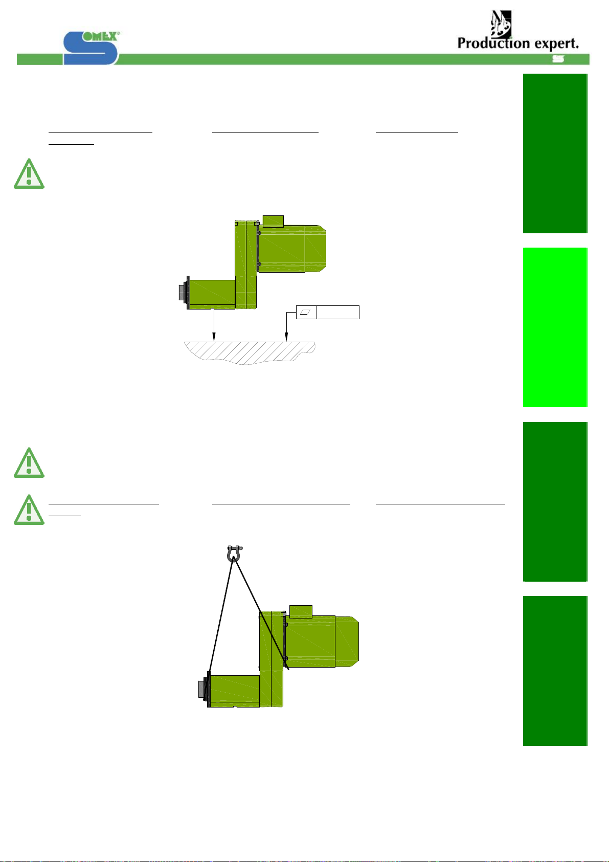
2.1 Montage
Indications relatives au
montage :
Défaut maxi admissible du
support pour la fixation des
unités d’usinage :
2. Start up
2.1 Installation
Installation instructions:
Maximum permissible surface
tolerance for correct machining
unit installation:
2. Inbetriebnahme
2.1 Montage
Montagehinweise:
Maximal zulässiger Fehler für
die Befestigung der
Bearbeitungseinheit:
La fixation de l’unité est
réalisée à l’aide de 4 vis H
M10.
Utiliser des vis de la classe de
qualité 8.8.
Raccordement des câbles
seulement après le montage
complet de l’unité.
The fixing of the unit is carried
out using 4 screws M10.
Screws of quality grade 8.8
must be used.
Connect the cables only after
the unit has been completely
installed.
Die Festlegung der Einheit wird
mittels 4 Schrauben M10
verwirklicht.
Schrauben der Güteklasse 8.8
müssen verwendet werden.
Anschluss der Kabel erst nach
vollständiger Montage der
Maschine.
Manutention correcte de
l’unité : Correct lifting of machine unit : Richtiges Heben der Einheit:
0.04/1000

Date de création : 19/11/07
Indice de révision : C 7
1. Indication de sécurité
1. Notes on safety
1. Sicherheitshinweise
2. Mise en service
2. Start up
2. Inbetriebnahme
3. Utilisation
3. Handling
3. Handhabung
4. Maintenance
4. Maintenance
4. Instandhaltung
Croquis des dimensions : Outline dimensions drawing: Maßbild :
MAX30B-ISO40
MAX30B-HSK63 MAX30B-ABS63
Réf. B1697 Réf. B1974
126
135
135
126
28+1
-0
12
11
14H7
90
168+15
-10
22
2.5
190
341
Ø138
(4x) M8 sur Ø120
2
Ø92-0.005
-0.025
Ø88.88-0.005
-0.025
20
160
105
200
370
122.5
70
32
27.5

Date de création : 19/11/07
Indice de révision : C 8
1. Indication de sécurité
1. Notes on safety
1. Sicherheitshinweise
2. Mise en service
2. Start up
2. Inbetriebnahme
3. Utilisation
3. Handling
3. Handhabung
4. Maintenance
4. Maintenance
4. Instandhaltung
Croquis des dimensions : Outline dimensions drawing: Maßbild :
MAX30-ISO40-BS
MAX30B Option joint tournant MAX30B Option rotating union MA30B Option
Drehdurchführung
MAX30-ISO40-BS Option joint
tournant MAX30-ISO40-BS Option
rotating union MA30-ISO40-BS Option
Drehdurchführung
100
130 x 130
DIN69871/DIN69872
DIN69871/DIN69872
DIN69871/DIN69872
96
Ø44
56
G3/8" NPT
Ø44
96
G3/8" NPT
Date de création : 19/11/07
Indice de révision : C 9
1. Indication de sécurité
1. Notes on safety
1. Sicherheitshinweise
2. Mise en service
2. Start up
2. Inbetriebnahme
3. Utilisation
3. Handling
3. Handhabung
4. Maintenance
4. Maintenance
4. Instandhaltung
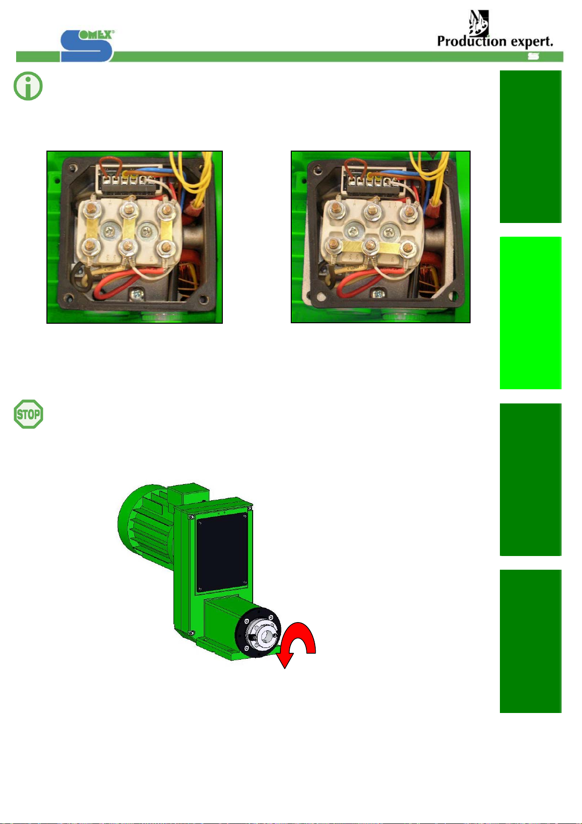
2.2 Asservissement
Alimentation du moteur :
230 - 460V, 50 - 60 Hz
2.2 Electrical connections
Motor power
230 - 460V, 50 - 60 Hz
2.2 Ansteuerung
Motor-Speisung
230 - 460V, 50 - 60 Hz
(A) (B)
Branchement 230V (A)
Branchement 400V (B)
Avant la mise en service de
l’unité s’assurer que le moteur
est câblé pour le bon sens de
rotation:
230 V connection Picture (A)
400 V connection Picture (B)
Before start-up, remove belt
from pulleys and make sure
that sense of motor rotation is
correct:
Anschluss 230 V (A)
Anschluss 400 V (B)
Vor der Inbetriebnahme der
Einheit ist zu gewährleisten,
dass der Motor für die richtige
Drehrichtung angeschlossen
ist:

Date de création : 19/11/07
Indice de révision : C 10
1. Indication de sécurité
1. Notes on safety
1. Sicherheitshinweise
2. Mise en service
2. Start up
2. Inbetriebnahme
3. Utilisation
3. Handling
3. Handhabung
4. Maintenance
4. Maintenance
4. Instandhaltung
2.3 Données techniques 2.3 Technical specifications 2.3 Technische Daten
Capacité de perçage Max Max Capacity of drilling Bohrkapazität Max Ø35 / 600 N/mm²
Couple max. transmissible Max. torque capacity Max übertrag. Drehmoment 300 N.m
Vitesse de rotation
roulements rouleaux Speed with tapered
bearings Drehzahlbereich
Kegelrollenlager 4 000 min -1
Vitesse de rotation
roulements contact oblique Speed with angular contact
bearings Drehzahlbereich
Schrägkugellager 9 200 min -1
Tolérances de concentricité Spindle concentricity Rundlaufgenauigkeit 0.01 mm
6 moteurs standard ISO, IP
55 6 Standard ISO motors,
IP55 6 Standard-ISO-Motore,
IP55 1.5 – 5.5 kW
Tension des moteurs à
50/60 Hz Standard voltage at 50/60
Hz Normalspannung 50/60 Hz 230-460 V
Exécution roulements à
rouleaux coniques Spindle tapered bearings Spindel mit Kegelrollenlager -K
Exécution roulements à
contact oblique Spindle angular contact
bearings Spindel mit
Schrägkugellager -S
Broche standard Standard spindle Standardspindel ISO40
Option: Autres broches Option: Other spindle Option: andere Spindel HSK63 – ABS63
Serreur 4 points fournis Includes HSK 4-points
clamping 4-Punkt-HSK Spannsatz
mitgeliefert HSK-C
Option : Changement
d’outil automatique
pneumatique
Option : Pneumatic quick
tool changer Option : Pneumatik
Werkzeugwechsler MAX30-BS
Option : Transmission
courroie crantée Option : Timing belt drive Option : Zahnriemenantrieb HTD 8MR30
Option : Joint tournant Option : Rotating Union Option : Drehdurchführung DEUBLIN
Poids Weight Gewicht 50 kg
Couleur Colour Farbe RAL6018
2.4 Conditions d’exploitation 2.4 Operating requirement 2.4 Betriebsbedingungen
Température ambiante Ambient temperatures Umgebungstemperaturen 5-50 °C
90% à 30°C
Taux d'humidité maxi Max. rel. Humidity Max. Feuchtigkeitsgehalt 65% à 50°C
230 - 460 V
Alimentation du moteur Motor power Motorspeisung 50 - 60 Hz
20 -255 V
Alimentation des
détecteurs Limit switch Schalterspeisung AC / DC
L’unité doit être protégée des
projections directes et/ou sous
pression, de liquide de coupe.
The unit must be protected
from direct flood coolant,
coolant mist and high pressure
coolant through the spindle
application.
Die Einheit muss vor direktem
Spritz-und Kühlwasser
geschützt werden

Date de création : 19/11/07
Indice de révision : C 11
1. Indication de sécurité
1. Notes on safety
1. Sicherheitshinweise
2. Mise en service
2. Start up
2. Inbetriebnahme
3. Utilisation
3. Handling
3. Handhabung
4. Maintenance
4. Maintenance
4. Instandhaltung
3. Utilisation
3.1 Exploitation
Changement de l’ensemble
Poulie/Courroie
3. Handling
3.1 Operation
Belt exchanging
3. Handhabung
3.1 Betrieb
Riemenwechsel
Desserrer les vis de fixation du
flasque moteur (1).
Détendre la courroie (2).
Démonter le carter arrière (3).
Procéder au changement de la
courroie.
Remonter, opération : (1), (2) et
(3) dans le sens inverse.
Loose motor flange’s screws
(1).
Relax belt tension (2).
Remove the rear housing
screws (3).
Replace the belt.
Reverse steps (1), (2) and (3).
Lösen der Schauben am
Motorenflansch (1).
Riemen entspannen (2).
Hinteres Gehäuse entfernen
(3).
Wechseln des Riemens.
Wieder Montage : (1), (2) und
(3) in umgekehrter
Reiheinfolge.
Pressurisation Pressurization Sperrluftanschluss
Pression : 0.1 à 0.2 bar
Raccordements : (2x) G1/8’’ Pressure : 0.1 to 0.2 bar
Connection : (2x) G1/8’’
Druck : 0.1 bis 0.2 bar
Anschluss: (2x) G1/8’’
(
3
)
(
2
)
(
1
)

Date de création : 19/11/07
Indice de révision : C 12
1. Indication de sécurité
1. Notes on safety
1. Sicherheitshinweise
2. Mise en service
2. Start up
2. Inbetriebnahme
3. Utilisation
3. Handling
3. Handhabung
4. Maintenance
4. Maintenance
4. Instandhaltung
Trous d’évacuation du carter de
transmission Transmission housing Plughole Löcher für die Evakuierung aus
dem Antriebskasten
Afin de faciliter l’évacuation du
liquide de coupe, deux trous
sont percés dans chaque carter
de transmission et obturés à la
livraison. En fonction de la
position de l’unité il faut libérer
un trou pour permettre
l’évacuation des liquides (Voir
schéma ci-dessous).
In order to facilitate the
evacuation of the cutting fluid,
two holes are bored in each
transmission housing and are
sealed with the delivery.
According to the position of the
unit it is necessary to release a
hole to allow the evacuation of
the liquids (See diagram
below).
Die Löcher dienen zur
Evakuierung von
eingedrungenem Kühlmittel. Je
nach Position der Einheit sind
die Stopfen zu entfernen (siehe
Abbildung unten).
1
2
3
4
Selon la position de montage
de l’unité le trou d’évacuation
de liquide à libérer est :
According to the position of the
assembly, the hole of
evacuation of liquid to be
released is :
Je nach Einbaulage der Einheit
sind folgende Stopfen zu
entfernen :
Position de montage
Position of assembly
Montage Position
N° du trou a débouché
Hole number to release
Nummer des zu entfernenden Stopfen
M1 3
M2 3 ou 4
M3 1 ou 2
M4 4
M5 1
M4M3
M5 M1 M2

Date de création : 19/11/07
Indice de révision : C 13
1. Indication de sécurité
1. Notes on safety
1. Sicherheitshinweise
2. Mise en service
2. Start up
2. Inbetriebnahme
3. Utilisation
3. Handling
3. Handhabung
4. Maintenance
4. Maintenance
4. Instandhaltung
Arrosage par le centre Thought the tool coolant Kühlmittelzufuhr:
SOMEX vous offre la possibilité
d’emmener le liquide de coupe
par le centre de la broche grâce
à un joint tournant.
Référence: 0300-00190
SOMEX offers a system for
feeding the cutting fluid through
the centre of the spindle with
the help of a DEUBLIN type
rotating union.
Reference code : 0300-00190
SOMEX gibt Ihnen die
Möglichkeit, die Kühlflüssigkeit
mit Hilfe einer
Drehdurchführung des Typs
DEUBLIN durch die
Spindelmitte durchlaufen zu
lassen.
Bestellnr. : 0300-00190
Précautions d'utilisation:
•Filtration du liquide de
coupe: 5µm
•Ne pas tourner à sec.
•Pression maxi: 105bar
•L'anti-rotation du joint
tournant est obtenue par le
flexible de raccordement ou
par une fourchette.
N'utiliser en aucun cas de
tube rigide.
•S'assurer que le flexible ne
soit pas tendu et qu'il ne se
tend pas lors de la mise
sous pression.
Usage precautions :
•Filtering for cutting fluid : 5
µm.
•No dry running.
•Maximum pressure : 105
bar
•Non rotation of the rotating
union is obtained with the
help of the connection hose
or a fork.
Do not use a rigid pipe in
any event.
•Make sure that the hose is
not taut, and that it is not
tensioned when pressure is
applied
Vorsichtsmaßnahmen bei
Verwendung:
•Filtrierung der
Kühlflüssigkeit: 5µm
•Nicht trocken drehen
lassen.
•Maximaldruck: 105 bar
•Gegendrehung des
Drehringes wird durch den
biegsamen
Anschlussschlauch Oder
einer Gabel erzielt.
Niemals ein Rohr
verwenden.
•Überprüfen, daß der
Schlauch nicht gespannt ist
und sich auch nicht bei
dem Unterdrucksetzen
spannt.
Démontage :
Avant de faire cette
manipulation assurez vous que
la broche est bien bloquée en
rotation.
Attention : Pas à gauche pour
le filetage du tirant et du joint
tournant
Disassembly :
Make sure the rotation of the
spindle is blocked before
disassembly.
Cautions: The spindle and the
rotating union threading is a left
sense
Abbau:
Bevor das durchgeführt wird,
überprüfen Sie daß die Spindel
blockiert ist.
Achtung: Linksgewinde
zwischen Zugstange und
Drehdurchführung.
Tirant
Le tirant livré (broche DIN2079-
SA40) permet de serrer les
portes outils DIN69871. Dans le
cas où ce dernier est du type
DIN2080, raccourcir le tirant de
25mm.
Drawbar
The drawbar who is delivered
(Spindle SA40-DIN2079) can
tighten the tool holders
DIN69871. In case it is the type
DIN2080, shorten the drawbar
of 25mm.
Zugstange
Gelieferte Zugstange (für
spindel DIN2079 SK40) ist
geeignet für
werkzeugaufnahme nach
DIN69871. In fall wo sie ein
DIN2080 Werzeug verwerden
müssen sie die zugstange von
25mm Abkürzen
Date de création : 19/11/07
Indice de révision : C 14
1. Indication de sécurité
1. Notes on safety
1. Sicherheitshinweise
2. Mise en service
2. Start up
2. Inbetriebnahme
3. Utilisation
3. Handling
3. Handhabung
4. Maintenance
4. Maintenance
4. Instandhaltung
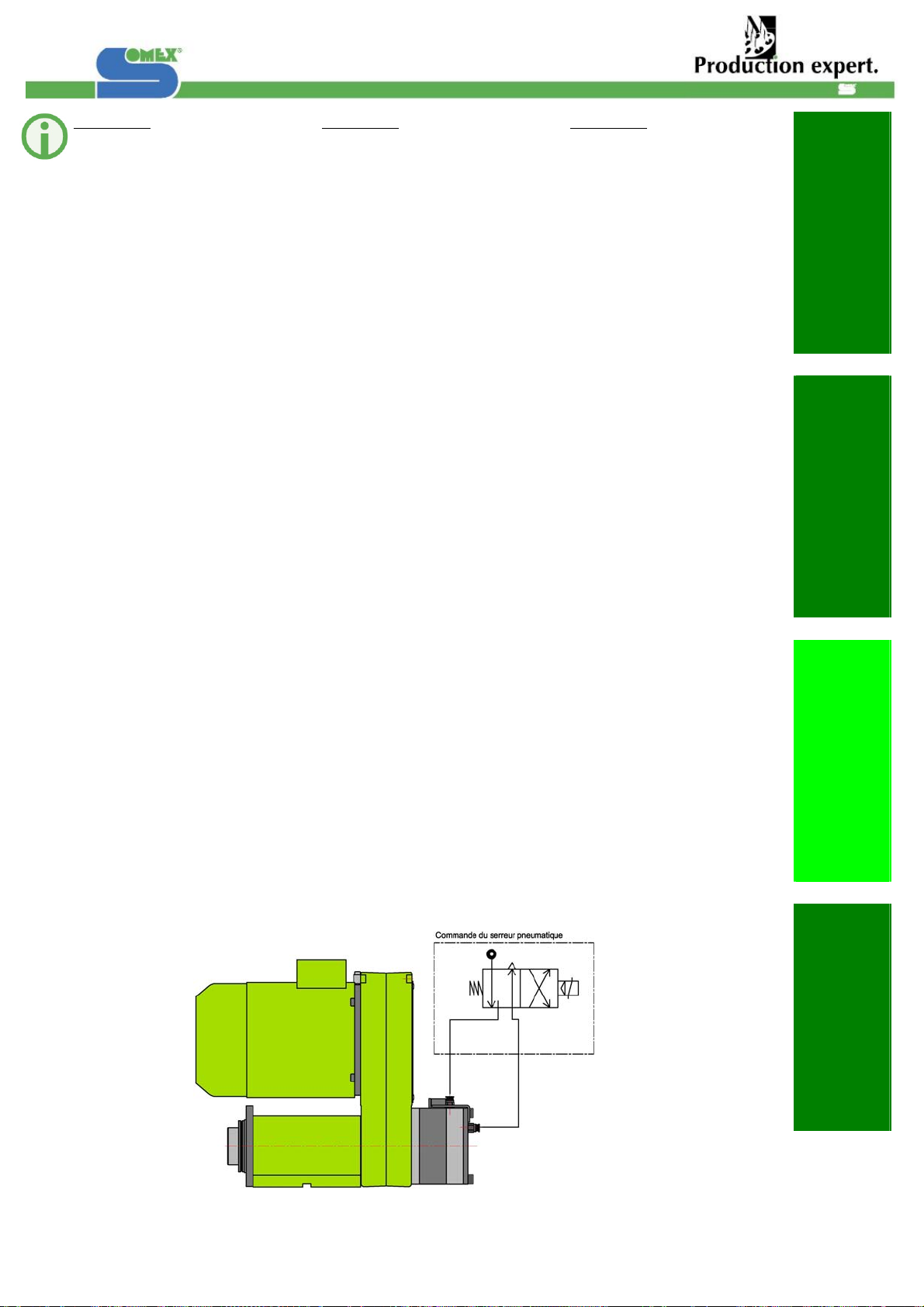
MAX30-BS MAX30-BS MAX30-BS
Fonctionnement :
Le maintien des outils dans le
cône de l'unité se fait grace à
un serreur d'outils.
L'effort de traction de l'outil
dans la broche est obtenu
grace à un empilage de
rondelles de type élastiques.
Le desserrage de l'outil se fait
en alimentant le vérin
pneumatique (pression de 6
bar) grace au raccord qui se
trouve à l'arrière de l'unité (G
1/8" tube Ø9).
Avant la mise en rotation de la
broche, il faut alimenter le
retour vérin (M5) qui se
trouvesur le tube arrière et
s'assurer que le détecteur
détecte le drapeau.
Operation:
The tool holder is held in the
machine spindles cone with a
tool clamping mechanism. The
retention load required to hold
the tool holder, in the cone, is
supplied with a stack of
washers (belleville spring
assembly).
The tool holder is released from
the cone with a pneumatic
cylinder. The pneumatic
cylinder compresses the stack
of washers releasing the tool
holder. Six bars (6 bar) of air
pressure are required to
compress the washers and
release the tool holder. Air is
supplied to the rear port of the
mounted pneumatic cylinder (G
1/8" coupling and a 9mm DIA
hose).
Before setting the spindle in
rotation the pneumatic piston
must be returned to it's rear
position (away from machine
spindle). This is necessary to
prevent the internal shaft that
actuates the pneumatic piston
from rubbing against the rear
end of the machine spindle.
The cylinder must be returned
to it's rear position by supplying
air pressure at the side port (G
1/8" coupling and a 9mm DIA
hose) of the pneumatic
cylinder.
Funktion :
Das Halten der Werkzeuge im
Kegel der Einheit ist mit einem
Werkzeugspanner möglich. Die
Zugkraft des Werkzeugs in der
Spindel wird mittels
Tellerfedern erreicht.
Das Lösen des Werkzeugs
macht sich durch den Anschluß
(G 1/8" Rohr Ø9) des
pneumatischen Kolbens (Druck
6 bar), der sich hinter der
Einheit befindet.
Bevor man die Spindel in
Drehung bringt, muss man den
Rückhub des Kolbens (M5) der
sich Seitlich am Zylinder
befindet steuern, und prüfen
dass der Endschalter das
Signal von der Fahne hat.
Exemple de branchements
pneumatique du Vérin
pneumatique :
Example of pneumatic
connections from the
pneumatic cylinder :
Beispiel für die Anschlüsse des
pneumatischen Zylinders :

Date de création : 19/11/07
Indice de révision : C 15
1. Indication de sécurité
1. Notes on safety
1. Sicherheitshinweise
2. Mise en service
2. Start up
2. Inbetriebnahme
3. Utilisation
3. Handling
3. Handhabung
4. Maintenance
4. Maintenance
4. Instandhaltung
Branchements électrique du
capteur du vérin pneumatique :
Electrical connections from the
pneumatic cylinder: Elektrischen Anschlüsse des
Sensors des
Pneumatikzylinders:
BU : Couleur Bleu
BN : Couleur Brun BU : Blue colour
BN : Brown colour BU: Farbe Blau
BN: Farbe Braun
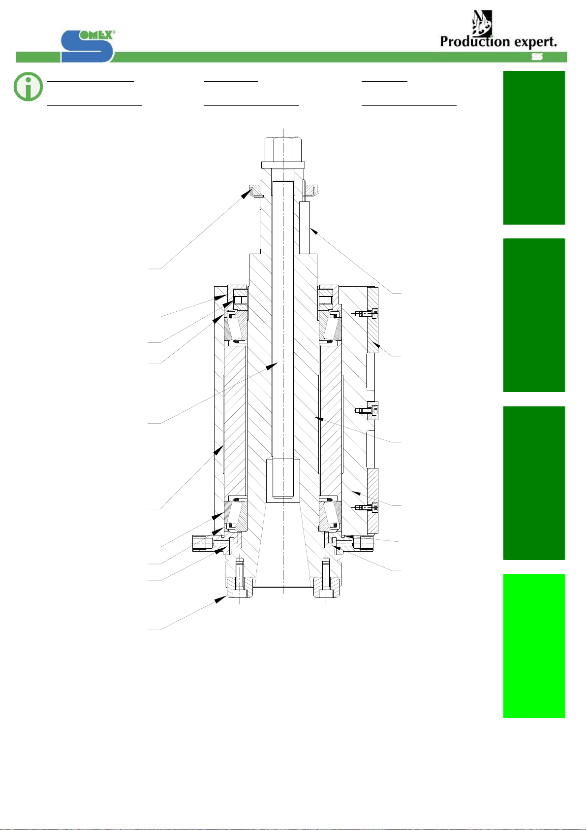
3.2 Réglages
MAX30-BS
Réglage complet du pot de
serrage (lors d'un changement
des rondelles élastiques par
exemple).
3.2 Adjustments
MAX30-BS
Complete setting of the
clamping System (after
replacement of spring rings for
example).
3.2 Stellung
MAX30-BS
Komplette Einstellung des
Werkzeugspanners ( Zum
Beispiel nach Austausch der
Tellerfedern)
Réglage du serrage
Relever les cotes B et S.
Calculer la cote R de la
manière suivante:
R = 176,12 + S – B
Monter le tirant, la pince, les
rondelles et le porte-outil.
Mettre en place la cote R.
Relever la cote T.
Réglage de l'éjection
Cone monté en broche.
Relever les cote C et D
Vérifier que :
C - D = J = 3mm
Si nécessaire retoucher la
pièce (1) pour obtenir les 3 mm.
Assurer le serrage
Désserrer l' écrou (2) et sortir le
cone de la broche
Remettre en place la cote T
Relever la cote R
R doit etre supérieur d'environ
1mm par rapport au R relever
dans le paragraphe ci dessus.
Setting of the clamping force
Recording of the dimensions B
and S
Calculation of the dimension
according to the following
Formula:
R = 176.12 + S – B
Installation of the drawbar, the
gripper, the rings and the cone
of the tool holder
Adjustment of the distance R
Recording of the dimension T
Setting of the ejection
Cone in the spindle
Recording of the dimensions C
and D
Please check that:
C - D = J = 3mm
If necessary, the part (1) has to
be adjusted in order to reach
the 3mm
Fastening of the clamping.
Unclamp of the bolt (2) and
draw up of the cone from the
spindle
Install again the dimension T
Recording the dimension R
R has to be 1mm larger than
the previous valve of R
recorded above.
Einstellung der Spannung
Maße B und S aufnehmen
Maße R wie folgend
ausrechnen:
R = 176,12 + S - B
Zugstange, Glocke,
Tellerfedern und der
Werkzeughalter zusammen
montieren.
Maß R einstellen
Maß T aufnehmen
Einstellung des Auswurfes
Der Werkzeughalter in die
Spindel
Maße C und D aufnehmen
Prüfen dass :
C - D = J = 3mm
Wenn notwendig, die Schraube
(1) nachnehmen um die 3mm
zu erhalten
Mutter (2) lösen und
Werkzeughalter von der
Spindel rausnehmen.
Maß T einstellen.
Maß R aufnehmen.
Prüfen dass R um 1mm großer
ist als im obigen Paragraph
gemessen.

Date de création : 19/11/07
Indice de révision : C 16
1. Indication de sécurité
1. Notes on safety
1. Sicherheitshinweise
2. Mise en service
2. Start up
2. Inbetriebnahme
3. Utilisation
3. Handling
3. Handhabung
4. Maintenance
4. Maintenance
4. Instandhaltung
B
S
R
T
C
D
J
1
2
MAX30-BS
MAX30-BS - Arrosage par le centre
MAX30-BS - Thought the tool coolant
MAX30-BS - Kühlmittelzufuhr
B
S
R
CD
J
12

Date de création : 19/11/07
Indice de révision : C 17
1. Indication de sécurité
1. Notes on safety
1. Sicherheitshinweise
2. Mise en service
2. Start up
2. Inbetriebnahme
3. Utilisation
3. Handling
3. Handhabung
4. Maintenance
4. Maintenance
4. Instandhaltung
4. Maintenance
4.1 Maintenance préventive
Lubrification
4. Maintenance
4.1 Preventive maintenance
Lubrication
4. Instandhaltung
4.1 Vorbeugende
Instandhaltung
Schmierung
Graissage des roulements de
broche :
Les roulements sont graissés à
vie à la graisse LUBCON L252.
Non miscible avec toute autre
graisse.
Spindle bearing lubrication :
The bearings are lubrificated
with LUBCON L252.
Grease, not miscible with any
other grease.
Schmierung der Spindellager :
Die Lager werden auf
Lebenszeit mit folgendem Fett
geschmiert : UBCON L252, und
ist mit keinen anderen Fett
mischbar.
Changement des roulements
Régler le jeu J par rectification
éventuelle de la bague (1).
Changing the bearings
Adjust play J by varying the
thickness of the ring (1) if
necessary.
Austauschen der Lager
Das Spiel J durch Ausrichten
des Rings (1) einstellen.
Numéro de série
Pour toute demande auprès du
fabricant, veuillez indiquer le
numéro de série de l’unité.
Serial number
All inquiries require serial
number identification.
Seriennummer
Für jeden Bedarf gegenüber
dem Hersteller, geben Sie bitte
die Seriennummer der Einheit
an.
J = 0+0.1
+0.02 J = 0+0.1
+0.02
1 1
Date de création : 19/11/07
Indice de révision : C 18
1. Indication de sécurité
1. Notes on safety
1. Sicherheitshinweise
2. Mise en service
2. Start up
2. Inbetriebnahme
3. Utilisation
3. Handling
3. Handhabung
4. Maintenance
4. Maintenance
4. Instandhaltung
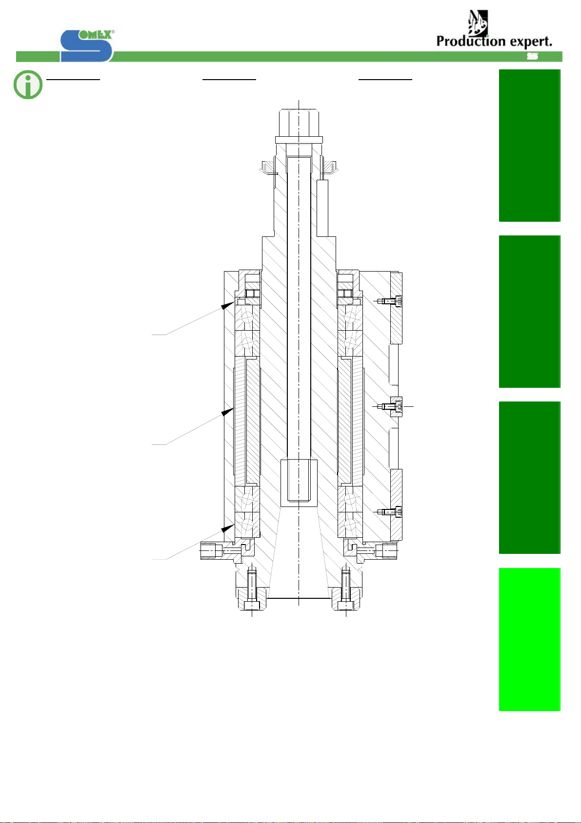
Pièces de rechange
Spare parts Ersatzteile
MAX30B – ISO40 – K MAX30B – ISO40 – K MAX30B – ISO40 – K
1
2
14
5
10
13
3
4
11
12
6
15
9
7 + 8
4
16
Date de création : 19/11/07
Indice de révision : C 19
1. Indication de sécurité
1. Notes on safety
1. Sicherheitshinweise
2. Mise en service
2. Start up
2. Inbetriebnahme
3. Utilisation
3. Handling
3. Handhabung
4. Maintenance
4. Maintenance
4. Instandhaltung
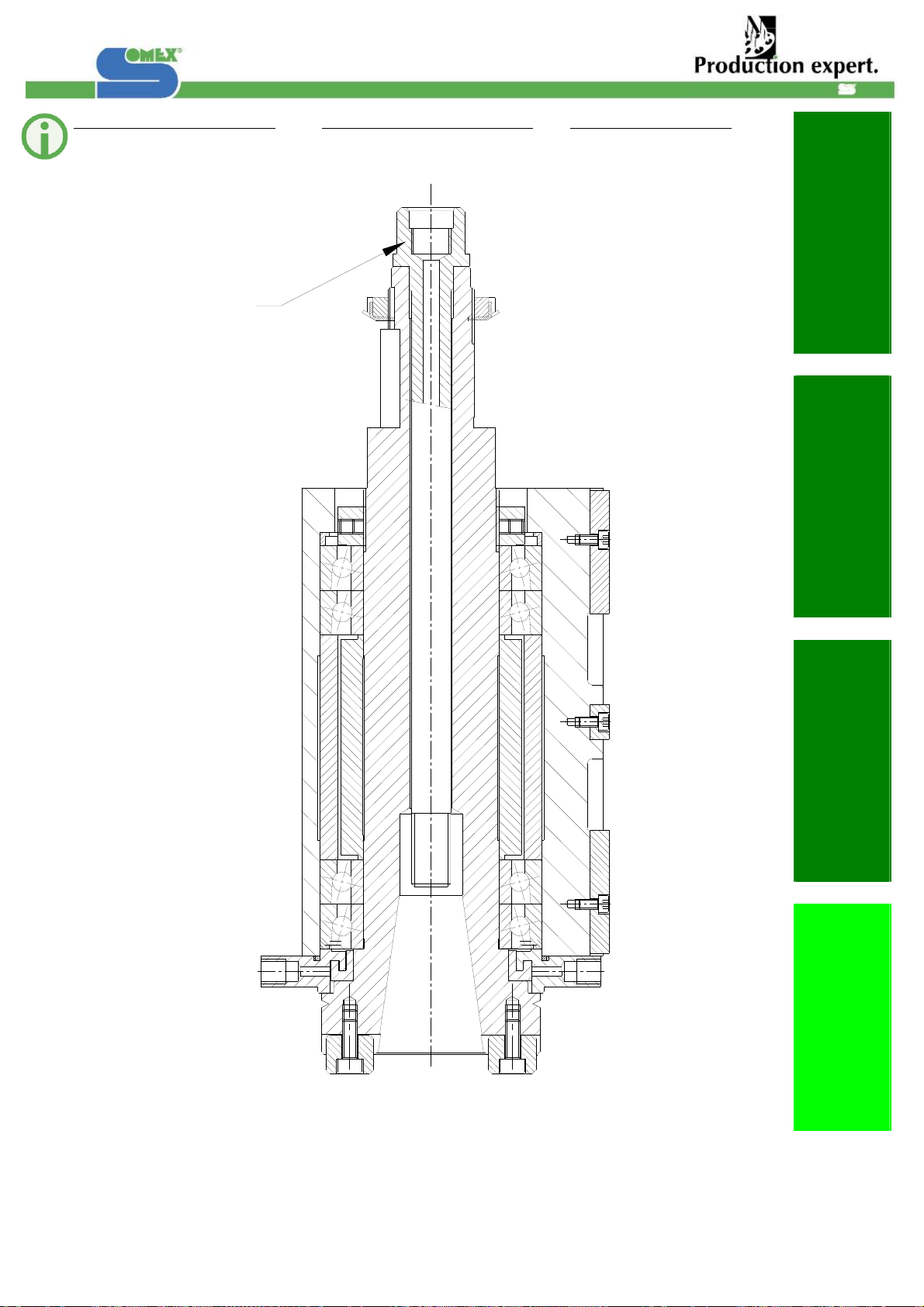
MAX30B - S
MAX30B - S MAX30B - S
1
2
3
Date de création : 19/11/07
Indice de révision : C 20
1
1. Indication de sécurité
1. Notes on safety
1. Sicherheitshinweise
2. Mise en service
2. Start up
2. Inbetriebnahme
3. Utilisation
3. Handling
3. Handhabung
4. Maintenance
4. Maintenance
4. Instandhaltung
Option arrosage par le centre
Option thought the tool coolant Option Kühlmittelzufuhr
Table of contents
Other Somex Industrial Equipment manuals


Popular Industrial Equipment manuals by other brands

Stanley
Stanley 71502 Instruction and service manual

Waters
Waters ACQUITY UPLC Overview and maintenance guide

Tronair
Tronair 06-5042 Series Operation & service manual

Rifox
Rifox RIFOmat 1222 operating manual

Scheppach
Scheppach DM460T instruction manual

ASGCO
ASGCO BC-2 Installation, operation, & maintenance instruction


