BossWeld ST 141X User manual

DC INVERTER MANUAL
2
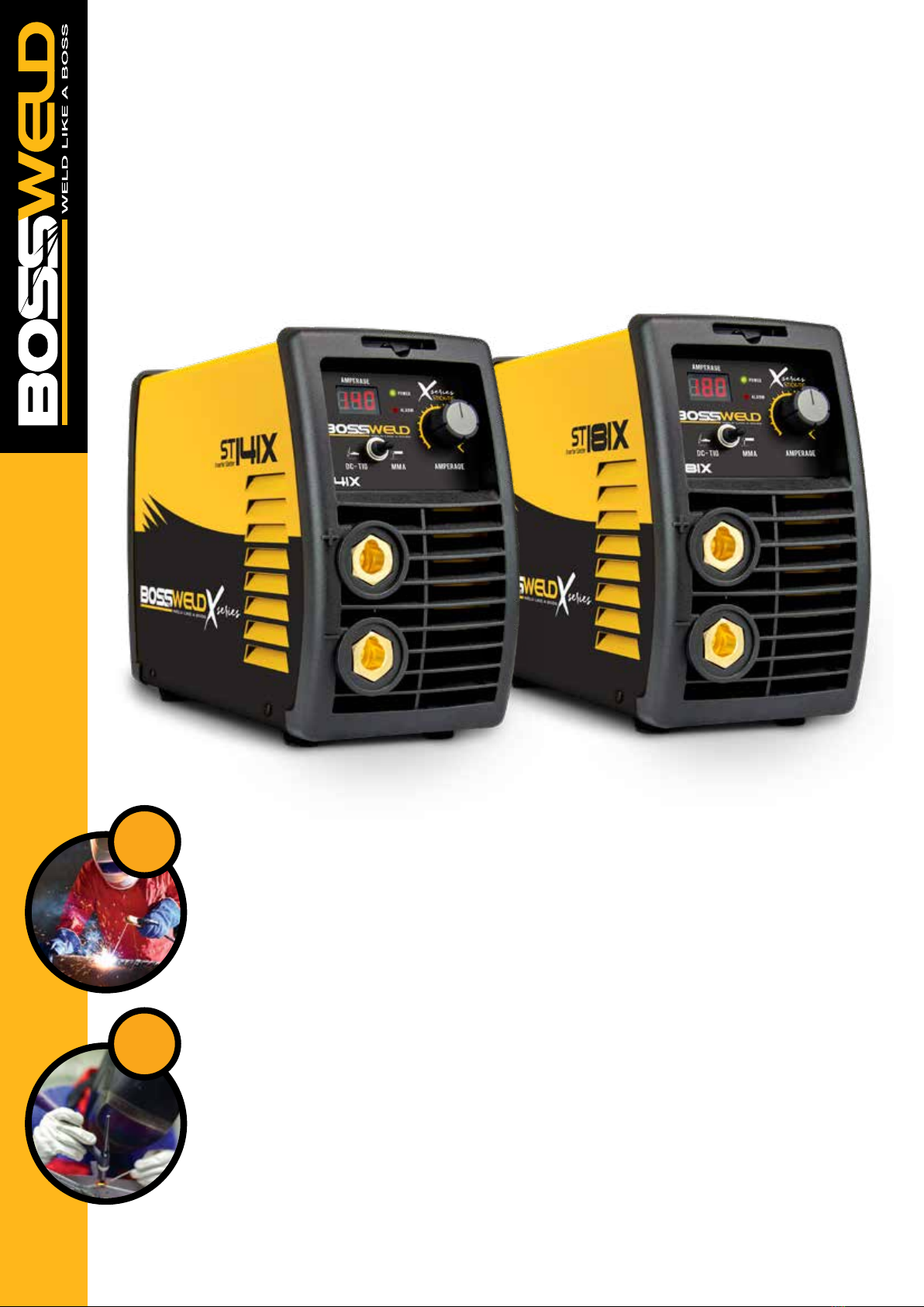
Thank you for choosing a BOSSWELD ST 141X / ST 181X Inverter DC MMA Welder
In this manual you will nd instructions on how to set up your welder along with general welding information
safety information and helpful tips. We encourage you to go online to our website for more tips and
troubleshooting as well as many welding resources.
The BOSSWELD ST 141X / ST 181X are the latest in IGBT MMA Stick Electrode Welder technology, this very
lightweight welding machine, is easy to use, generating a very smooth and stable output, ideal for welding jobs
around the home, farm, workshop or on site.
We truly hope you enjoy using your welder!
Every effort has been made to ensure that this manual has been prepared accurately, however errors and omissions are excepted.
BOSSWELD is a trademark of Dynaweld Industrial Supplies Pty Ltd.
MMIG
• Simple to learn
• MIG Wire is fed through the gun to create the weld pool
• Gas or flux prevents oxidisation in the weld
• Weld with or without gas
• Point and pull the trigger
• Great for maintenance, small projects
& automotive repairs
METAL TYPES
Mild steel, stainless steel & aluminium
SSTICK
• Easiest process to learn
• Best choice for quick repairs
• Slower than MIG welding
• Forgiving in dirty/rusty environments
• Not recommended for thin sheet metal welding
METAL TYPES
Mild steel, stainless steel & cast iron
TTIG
• Gives a better weld finish
• Accurate heat control
• Considered the most challenging process to learn
• Good way to weld thin material
• Argon gas is required
METAL TYPES
Mild steel, stainless steel & aluminium
PPLASMA CUTTING P
• Wide range of uses to cut conductive metals
• Uses an accelerated jet of hot plasma
• High speed/low cost cutting method
• Used extensively replacing gas cutting methods
• Air compressor is required
METAL TYPES
Mild steel, stainless steel & aluminium

3
CONTENTS PAGE
WARRANTY 4
BOX CONTENTS 5
WARNINGS 6
MACHINE CARE / SAFETY INSTRUCTIONS 7
WORK AREA SAFETY 8
MAINTENANCE & DISPOSAL 9
FRONT & REAR PANEL LAYOUT 10
STICK / MMA WELDING SETUP 11-12
GENERAL MMA WELDING 13-14
TIG WELDING SETUP 15-16
LIFT ARC START 17
TIG TORCH SPARES 18
GENERAL TIG WELDING 19-20
TROUBLE SHOOTING 21

4
DO NOT GRIND YOUR PLUG
This will void any warranty on your machine
WARRANTY
This warranty is in addition to the statutory warranty provided under Australian Consumer Law, but does not
include damage resulting from transport, misuse, neglect or if the product has been tampered with.
The product must be maintained as per this manual, and installed and used according to these instructions on
an appropriate power supply. The product must be used in accordance with industry standards and acceptable
practice.
Special n ote:
If this welders duty cycle is exceeded the welder will enter “thermal overload” which will
automatically stop the welding output in order to protect, both the user and the welder. You will know
the welder has gone into thermal overload when the overload error indicator light is illuminated.
The welder will then cool itself down, and once the overload error indicator light is no longer
illuminated, welding can then re-commence.
Please note. Exceeding the machine’s duty cycle, cannot be considered grounds for warranty or return.
This warranty covers the materials used to manufacture the machine and the workmanship used to produce the
item. This Warranty does not cover damage caused by:
1. Normal wear and tear due to usage
2. Misuse /abuse or Neglect of the item
3. Transport / handling breakages
4. Lack of maintenance, care and cleaning
5. Environmental factors, such as usage in temperatures exceeding 40 degrees, above 1000mt sea level, rain,
water, excessive damp, cold or humid conditions.
6. Improper setup or installation
7. Use on Incorrect voltage or non authorised electrical connections and plugs
8. Use of non standard parts
9. Repair, case opening, tampering with, modications to any part of the item by non authorised BOSSWELD
repairers.
This warranty covers the machine only and does not include Torches, Leads, Earth Clamps, Electrode holders,
Plasma Torches, Tig Torches and any of the parts on those items unless there is a manufacturing fault.
1. REGISTRATION
Purchasers are encouraged to register for warranty on our website. www.bossweld.com.au/warranty
2. TIME PERIOD - 3 Years (ST 141X) (ST 181X)
A warranty claim must be made within 3 years from the date of purchase of this product. Any claim must include
proof of purchase.
3. HOW TO MAKE A CLAIM - NEED SOME HELP?
• Visit our website www.bossweld.com.au/troubleshooting for many helpful tips and guides to assist with the
setup and usage of your new machine. Still stuck….?
• Call the BOSSWELD Helpdesk on 1300 899 710 for over the phone assistance.
• If the machine is not operational then return the item to the place of purchase.
BOSSWELD MAKES NO OTHER WARRANTY, EXPRESS OR IMPLIED. THIS WARRANTY IS EXCLUSIVE
AND IN LIEU OF ALL OTHERS, INCLUDING, BUT NOT LIMITED TO ANY WARRANTY OF
MERCHANTABILITY OR FITNESS FOR ANY PARTICULAR PURPOSE.
Note: Warranty will be void if 15Amp plug is ground down (ST 181X)
5
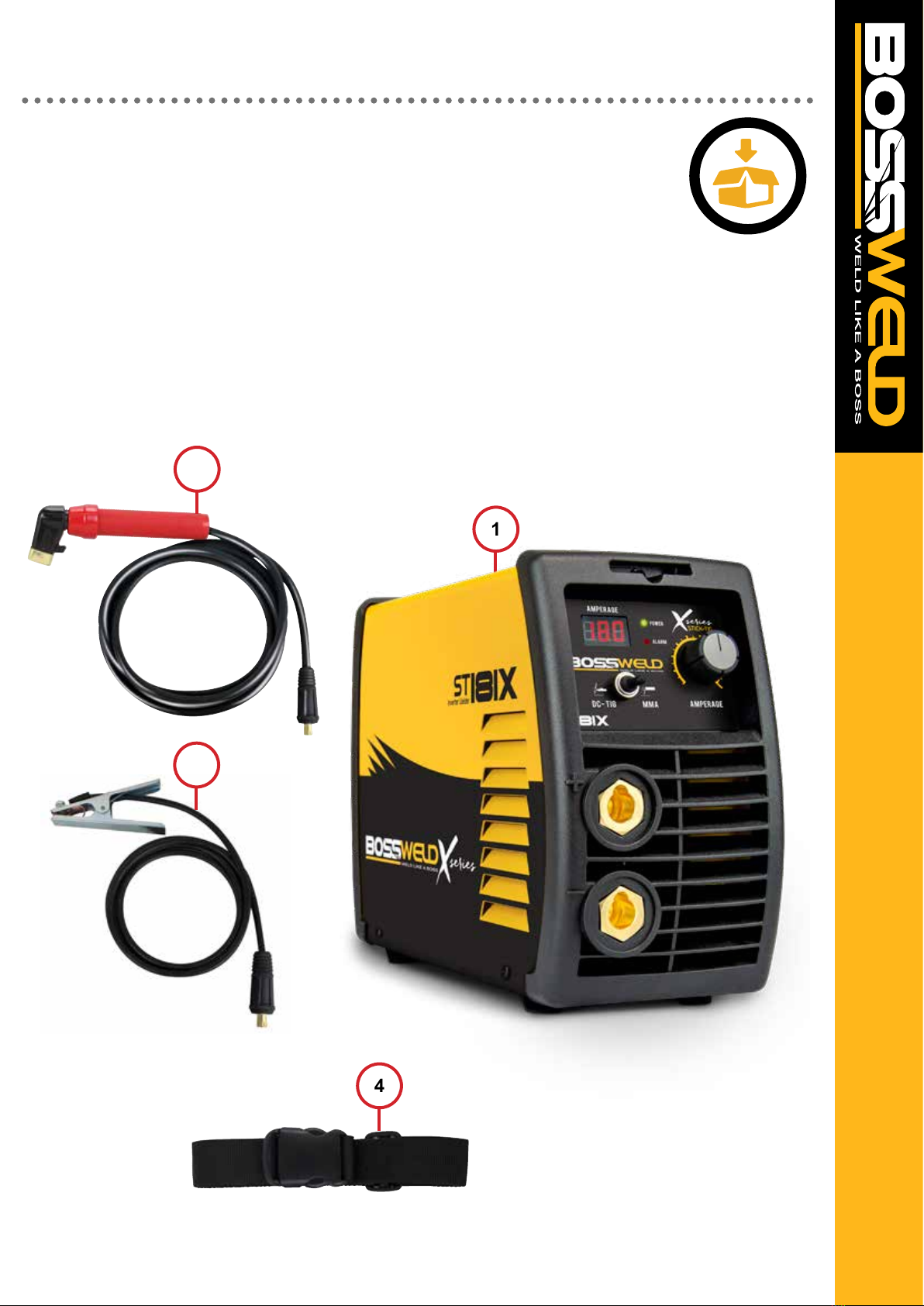
BOSSWELD ST 141X / ST 181X Inverter DC MMA Arc Welder Box Contents
1. BOSSWELD ST 141X or ST 181X Inverter DC MMA Arc Welder
2. Electrode Holder Lead
3. Welding Earth Lead
4. Carry Strap
5. Owners Manual (not shown)
1
2
4
3

6
The device and packaging material are not toys! Children must not be allowed to play with the machine and its
accessories. Plastic parts and packaging are choking risks for children.
• Open the packaging and remove the welder carefully.
• Check that the delivery is complete.
• If possible, store the packaging until the warranty period has expired.
PERSONAL PROTECTIVE EQUIPMENT (PPE)
GLOVES AND PROTECTIVE CLOTHING
Use protective gloves and re resistant protective clothing when welding.
Avoid exposing skin to ultraviolet rays produced by the arc.
WELDING HELMET
Under no circumstances should the welder be operated unless the operator is wearing a
welding helmet to protect the eyes and face. There is serious risk of eye damage if a helmet is
not used. The sparks and metal projectiles can cause serious damage to the eyes and face.
The light radiation produced by the arc can cause damage to eyesight, and burns to skin.
Never remove the welding helmet whilst welding.
SAFETY GLASSES
After welding use appropriate safety glasses when brushing, chipping or grinding the slag from
the weld.
OTHER PERSONS
Ensure that other persons are screened from the welding arc and are at least 15 metres away
from the work piece. Always ensure that the welding arc is screened from onlookers, or people
just passing by. Use screens if necessary, or non-reecting welding curtain. Do not let children
or animals have access to the welding equipment or to the work area.
SWITCHING OFF
When the operator has nished welding they must switch the welder off.
DO NOT put the electrode holder down with the welder switched ON.
When leaving the welder unattended, move the ON/OFF switch to the OFF position and
disconnect the welder from the electrical mains supply.
Do not leave hot material unattended after welding.
FUMES &GASES ARE DANGEROUS
Smoke and gas generated whilst welding or cutting can be harmful to people’s health. Welding
produces fumes and gases. Breathing these fumes and gases can be hazardous to your health.
• Do not breathe the smoke and gas generated whilst welding or cutting, keep your head out of
the fumes
• Keep the working area well ventilated, use fume extraction or ventilation to remove welding
fumes and gases.
• In conned or heavy fume environments always wear an approved air-supplied respirator.
Welding fumes and gases can displace air and lower the oxygen level causing injury or
death. Be sure the breathing air is safe.
• Do not weld in locations near de-greasing, cleaning, or spraying operations.
The heat and rays of the arc can react with vapours to form highly toxic and irritating gases.
• Materials such as galvanized, lead, or cadmium plated steel, containing elements that can
give off toxic fumes when welded. Do not weld these materials unless the area is very well
ventilated, and or wearing an air supplied respirator.
WARNING
7
Keep the welding cables, earth clamp and electrode holder in good condition. Failure to do this can result in
poor welding quality, which could be dangerous in structural situations.
Prior to use, check for breakage of parts and any other conditions that may affect operation of the welder.
Any part of the welder that is damaged should be carefully checked to determine whether it will perform its
intended function whilst being safe for the operator. Any part that is damaged should be properly repaired, or
replaced by an authorised service centre.
IMPROPER USE
It is hazardous to use the welding machine for any work other than that for which it was designed e.g. do not
use welder for thawing pipes.
HANDLING
Ensure the handle is correctly tted. As welding machines can be heavy, always use safe lifting practices when
lifting.
POSITION AND HANDLING
To reduce risk of the machine being unstable / danger of overturning, position the welding machine on a
horizontal surface that is able to support the machine weight. Operators MUST NOT BE ALLOWED to weld in
raised positions unless safety platforms are used.
WARNING
The user of this welder is responsible for their own safety and the safety of others. It is important to read,
understand and respect the contents of this user guide. When using this welder, basic safety precautions,
including those in the following sections must be followed to reduce the risk of re, electric shock and personal
injury. Ensure that you have read and understood all of these instructions before using this welder.
Persons who are not familiar with this user guide should not use this welder. Keep this booklet in a safe place
for future reference.
TRAINING
The operator should be properly trained to use the welding machine safely and should be informed about the
risks relating to arc welding procedures. This user guide does not attempt to cover welding technique. Training
should be sought from qualied / experienced personnel on this aspect, especially for any welds requiring a high
level of integrity for safety.
SERIOUS FIRE RISK
The welding process produces sparks, droplets of fused metal, metal projectiles and fumes.
This constitutes a serious re risk. Ensure that the area in which welding will be undertaken is clear of all
Inammable materials. It is also advisable to have a re extinguisher, and a welding blanket on hand to protect
work surfaces.
MACHINE CARE / SAFETY
SAFETY INSTRUCTIONS

8
Ensure a clear, well lit work area with unrestricted movement for the operator.
The work area should be well ventilated, as welding emits fumes which can be dangerous.
Always maintain easy access to the ON/OFF switch of the welder, and the electrical mains supply.
Do not expose the welder to rain and do not operate in damp or wet locations
WORK AREA
Where welding must be undertaken in environments with increased risk of electric shock, conned spaces or in
the presence of ammable or explosive materials, it is important that the environment be evaluated in advance
by an “expert supervisor”. It is also recommended that welding in these circumstances be carried out in the
presence of persons trained to intervene in emergencies.
AVOID ELECTRICAL CONTACT
Use adequate electrical insulation with regard to the electrode, the work piece and any accessible earthed metal
parts in the vicinity. Avoid direct contact with the welding circuit. The no load voltage between the earth clamp
and the electrode can be dangerous under certain circumstances.
Note: For additional protection from electric shock. It is recommended that this welder be used in conjunction
with a residual current device (RCD) with rated residual current of 30MA or less.
In general the use of extension leads should be avoided. If used however, ensure that the extension lead is
used with the welder is of a suitable current rating and heavy duty in nature that MUST have an earth
connection. If using the welder outdoors, ensure that the extension lead is suitable for outdoor use. Always keep
extension leads away from the welding zone, moisture and any hot materials.
WELDING SURFACES
Do not weld containers or pipes that hold, or have held, ammable liquids or combustible gases or pressure.
Do not weld on coated, painted or varnished surfaces as the coatings may ignite, or can give off dangerous
fumes.
WORK PIECE
When welding, the work piece will remain at high temperature for a relatively long period. The operator must not
touch the weld or the work piece unless wearing welding gloves. Always use pliers or tongs. Never touch the
welded material with bare hands until it has completely cooled.
VOLTAGE BETWEEN ELECTRODE HOLDERS OR TORCHES
Working with more than one welding machine on a single work piece, or on work pieces that are connected,
may generate a dangerous accumulation of no-load voltage between two different electrode holders or torches,
the value of which may reach double the allowed limit.

9
WARNING
Before starting any cleaning, or maintenance procedures on the welding machine, make sure that it is switched
OFF and disconnected from the mains supply.
There are no user serviceable parts inside the welder. Refer to a qualied service personnel if any internal
maintenance is required. After use, wipe the welder down with a clean soft dry cloth.
Regular inspection of the supply cord is required and if damaged is suspected, it must be immediately replaced
by the manufacturer, its service agent or similarly qualied persons in order to avoid a hazard
STORAGE/ TRANSPORT
Store the welder and accessories out of children’s reach in a dry place. If possible store the welder in the
original packaging. The appliance must unconditionally be secured against falling or rolling over during
transport.
DISPOSING OF THE PACKAGING
Recycling packaging reduces the need for landll and raw materials. Reuse of the recycled material
decreases pollution in the environment. Please recycle packaging where facilities exist. Check with your local
council authority for recycling advice.
DISPOSING OF THE WELDER
Welders that are no longer usable should not be disposed of with household waste but in an environmentally
friendly way. Please recycle where facilities exist. Check with your local council authority for recycling advice.
MAINTENANCE
DISPOSAL
10
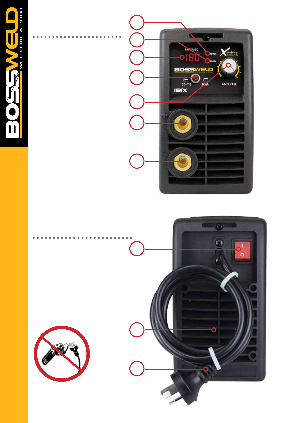
FRONT PANEL
1. Power Indicator Light
2. Overload Error Indicator
3. Digital Display
4. MMA / TIG switch
5. Current Adjustment Knob
6. Positive Output Connection Socket
7. Negative Output Connection Socket
REAR PANEL
8. Mains Power Switch 10Amp
- ST 141X
Mains Power Switch 15Amp
- ST 181X
9. Cooling Fan
10. 240V AC Mains Power Cord
2
3
4
5
1
6
7
8
10
9
Note: Warranty will be void if
15Amp plug is ground down

11
MACHINE SET UP STICK / MMA
2. Connect earth Clamp
to the terminal
2. Connect Electrode holder
to the terminal
Note: The below image shows setup for DCEP / Negative Polarity
(Most Common application)
Note: Pictures may vary from your machine model
Plug the machine 10Amp (EVO 141) or 15Amp
(ST 181X) input power lead into the wall socket,
e
nsuring that the power switch on the machine
is in the OFF position.
Connect earth clamp rmly to work-piece
ensuring that the clamp makes good contact
with bare metal.
Assemble Arc and Earth leads into the
welding terminals depending on requirements
of electrodes. Refer to your electrode packet
for polarity and current requirements.
• DCEP/ Negative Polarity (most common application)
- Earth clamp connector into the negative terminal.
- Electrode holder connector into the positive terminal.
•DCEN/Straight Polarity
- Earth clamp connector into the Positive terminal.
- Electrode holder connector into the Negative terminal.
Take electrode holder and insert bare metal
rod end of electrode and twist red handle to
clamp electrode.
1 3
2 4
12
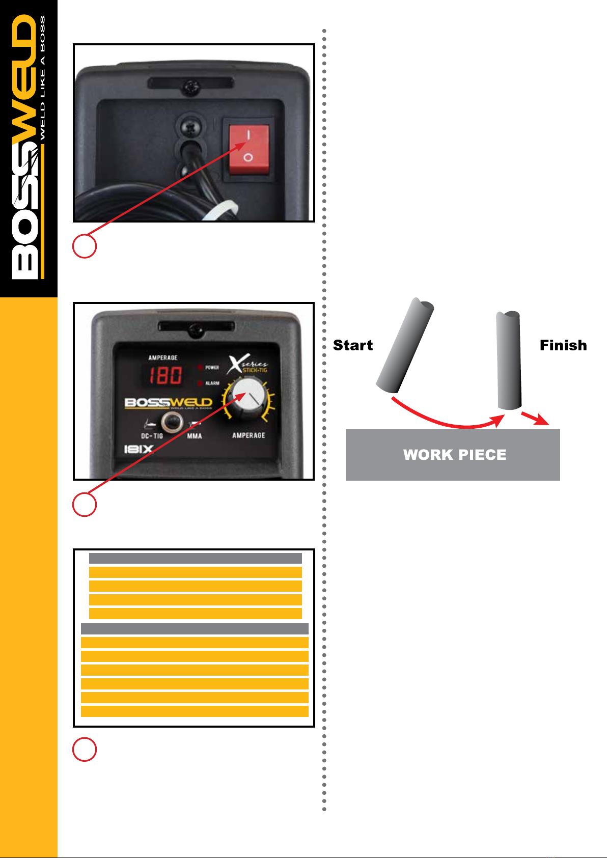
Select your required current by turning the
Welding Parameter Adjustment Knob.
Ensure the electrode/electrode holder is not
near the work-piece or can earth out, turn the
machine on using the mains power switch.
The front displays will light up and the cooling
fan will start.
5
6
Please see table on page 13 as a guide to
Welding Parameters.
7
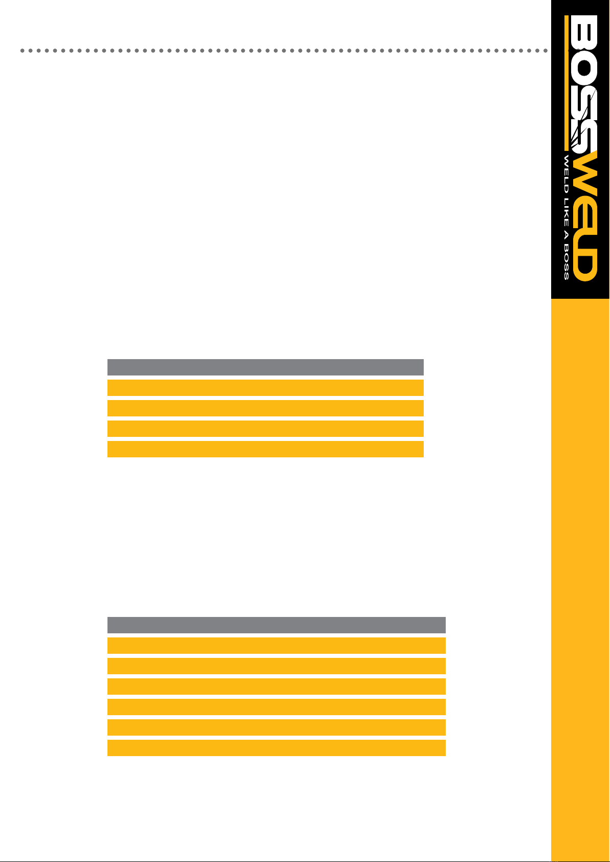
Amperage Selection Guide
Rod Size/ Gauge Welding Current
1.6mm 40-50 Amps
2.0mm 50-75 Amps
2.5mm 75-105 Amps
3.2mm 105-140 Amps
4.0mm 140-160 Amps
Average Metal Thickness Electrode Size
1.0 - 2.0mm 2.0mm
2.0 - 5.0mm 2.6mm
5.0 - 8mm 3.2mm
8.0mm + 4.0mm
Note: Pictures may vary from your machine model
STARTING THE ARC (SCRATCH)
The welding arc is obtained when the welding current is
forced across a gap between the electrode tip and the
workpiece. A welder must be able to strike and establish
the correct arc easily and quickly.
The scratching method is easier for beginners. The elec-
trode is moved across the plate inclined at an angle, as
you would strike a match. As the electrode scratches the
plate an arc is struck. When the arc has formed,
withdraw the electrode momentarily to form an
excessively long arc, then return to optimal arc length.
The optimal arc length, or distance between electrode
and puddle, is the same as the diameter of the
electrode (the actual metal part within the ux covering).
Holding the electrode too closely to the joint
decreases welding voltage, which creates an erratic arc
that may extinguish itself.
13
Amperage Selection Guide
Rod Size/ Gauge Welding Current
1.6mm 40-50 Amps
2.0mm 50-75 Amps
2.5mm 75-105 Amps
3.2mm 105-140 Amps
4.0mm 140-160 Amps
WELDING CURRENT
Welding current level is determined by the size of electrode - the normal operating range and current are
recommended by manufacturers. Typical operating ranges for a selection of electrode sizes are illustrated in
the table. As a rule of thumb when selecting a suitable current level, an electrode will require about 40 Amps
per millimetre (diameter). Therefore, the preferred current level for a 4mm diameter electrode would be 160
Amps, but the acceptable operating range is 140 to 180 Amps. It is important to match the machine to the job
Average Metal Thickness Electrode Size
1.0 - 2.0mm 2.0mm
2.0 - 5.0mm 2.6mm
5.0 - 8mm 3.2mm
8.0mm + 4.0mm
ELECTRODE SIZE SELECTION
Electrode size selection will be determined by the thickness of the section being welded. A thicker section will
need a larger diameter electrode. The table below shows the maximum size of electrodes for average
thicknesses of section (based on General Purpose 6013 Electrode).
TIPS
• Keep the welding current as low as possible for the job at hand to maintain the best duty cycle from your
welding machine, prevent the ux from burning and make slag removal easier.
• To break the circuit withdraw the electrode from the work piece. Be careful with the end of the electrode,
as it will be HOT. Provided the current setting is correct, the surface of the work piece will also melt by the
intensity of the electric arc. A degree of “penetration” is thereby obtained, and a complete “fusion” of the
work piece and the deposited electrode is met.
• If the transformer overheats, the overload cut-out protector will activate and cut off. The light will illuminate
to show that the cut out has operated.
• After cooling, the protector will reconnect the supply circuit and the welder will be ready for further use.
Note: If the duty cycle of the machine is exceeded, the thermostatic protection will activate and the
machine will cut out, to cool down.
14
MANUAL METAL ARC PROCESS (MMA WELDING)
When an arc is struck between the metal rod (electrode) and the workpiece, both the rod and workpiece
surface melt to form a weld pool. Simultaneous melting of the ux coating on the rod will form gas and slag
which protects the weld pool from the surrounding atmosphere. The slag will solidify and cool and must be
chipped off the weld bead once the weld run is complete (or before the next weld pass is deposited).
The process allows only short lengths of weld to be produced before a new electrode needs to be inserted in
the holder. Weld penetration is low and the quality of the weld deposit is highly dependent on the
skill of the welder.
TYPES OF ELECTRODES
Arc stability, depth of penetration, metal deposition rate and positional capability are greatly inuenced by the
chemical composition of the ux coating on the electrode. There are many types of Electrodes, and these
are generally matched to the base metal. For example if welding Mild Steel then select a Mild Steel (General
Purpose Electrode). Electrodes are identied by a universal numbering system (AWS Type code).
Electrodes are often packed in sealed packaging to keep moisture out. However, if a pack has been opened
or damaged, it is essential that the electrodes are redried according to the manufacturer’s instructions.
ARC FORCE
Also called Dig and Arc Control. Gives a power source variable additional amperage during low voltage
(short arc length) conditions while welding. Helps avoid “sticking” stick electrodes when a short arc
length is used.
POWER SOURCE
Electrodes can be operated with AC and DC power supplies. Not all DC electrodes can be operated on AC
power sources; however AC electrodes may be used on either AC or DC
Base Metal Electrode Type Type
Mild Steel Mild Steel General Purpose 6013
Stainless Steel Stainless Steel 316L 316L
Dissimilar Metals Dissimilar 680 312
Cast Iron Nickel Arc 98 Ni99
High Strength Steel Low Hydrogen TC16
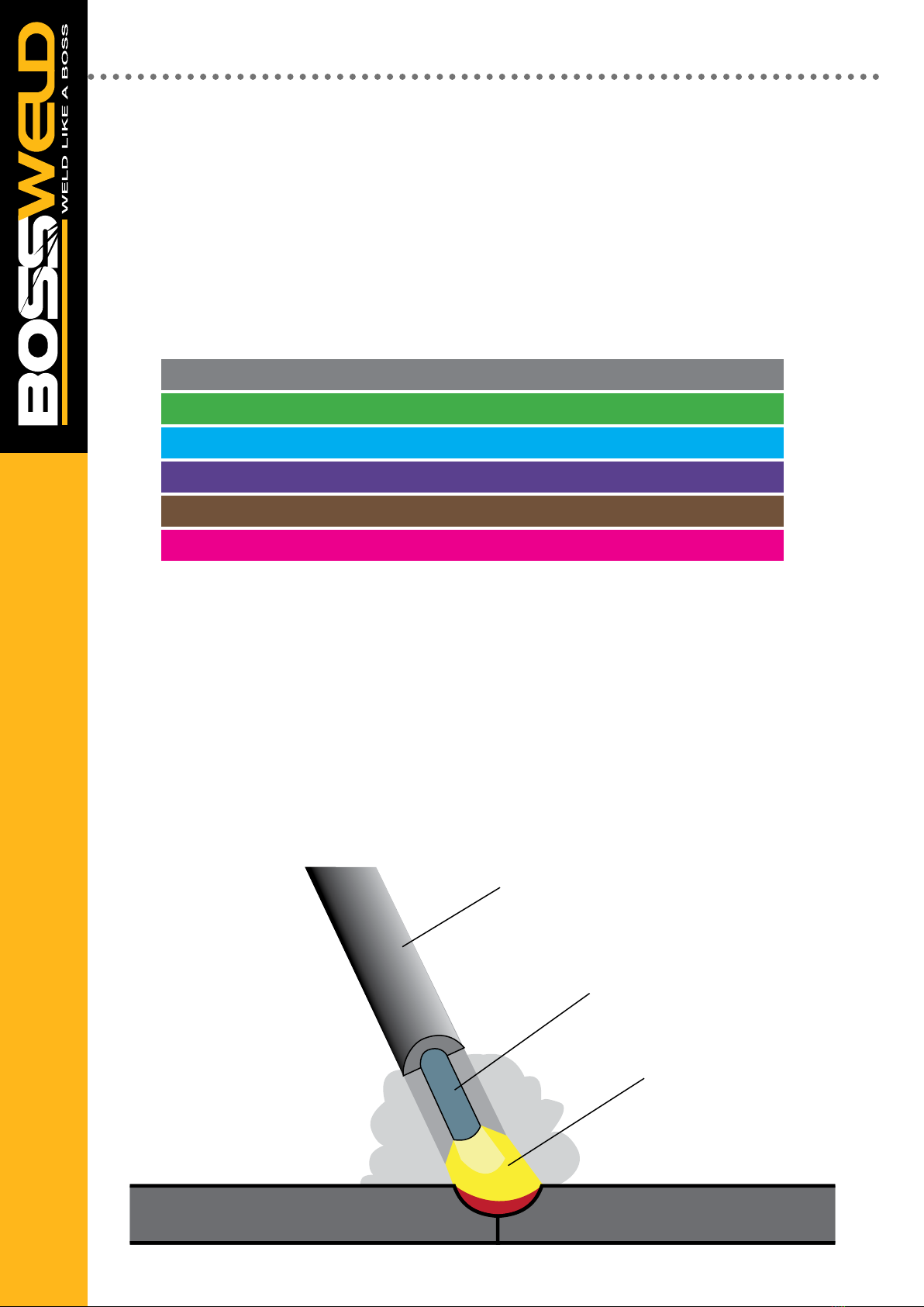
TRIGGER
WELDING WIRE
FLUX COATING
ROD
ARC
CONTACT TIP
DROPLETS
SHIELDING GAS
ARC
MOLTEN WELD METAL
SHROUD
WORK PIECE WORK PIECE
WORK PIECE WORK PIECEWORK PIECE WORK PIECE
WORK PIECE WORK PIECE
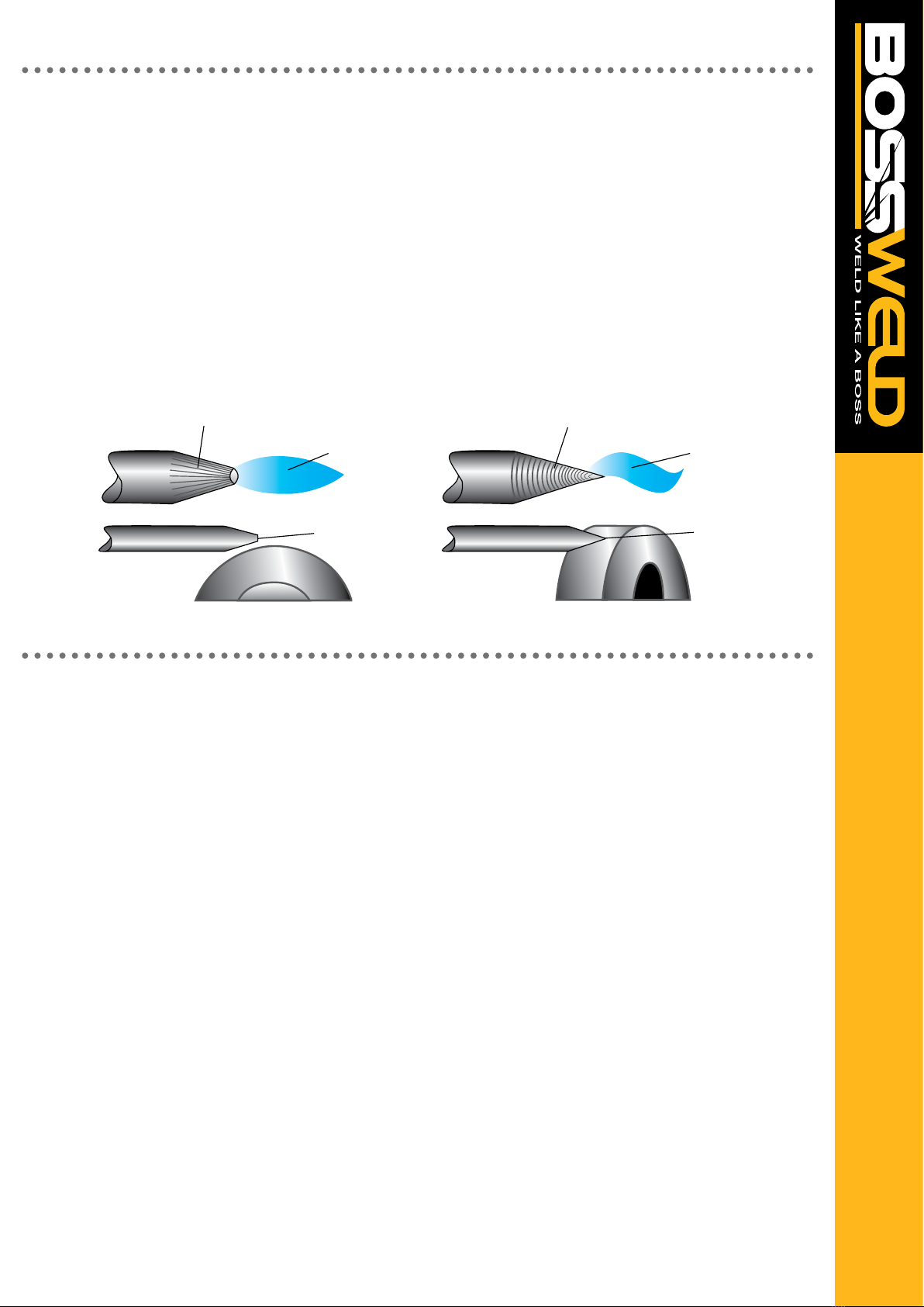
STRAIGHT GROUND
CORRECT PREPERATION - STABLE ARC INCORRECT PREPERATION - STABLE ARC
RADIAL GROUND
ARC WANDER
TUNGSTEN ELECTRODE
GAS LENS
STABLE ARC
FLAT TIP POINTED TIP
GRINDING WHEELGRINDING WHEEL
FILLER WIRE
Note: Do not use wheel for other jobs or tugsten can become contaminated and cause lower weld quality
15
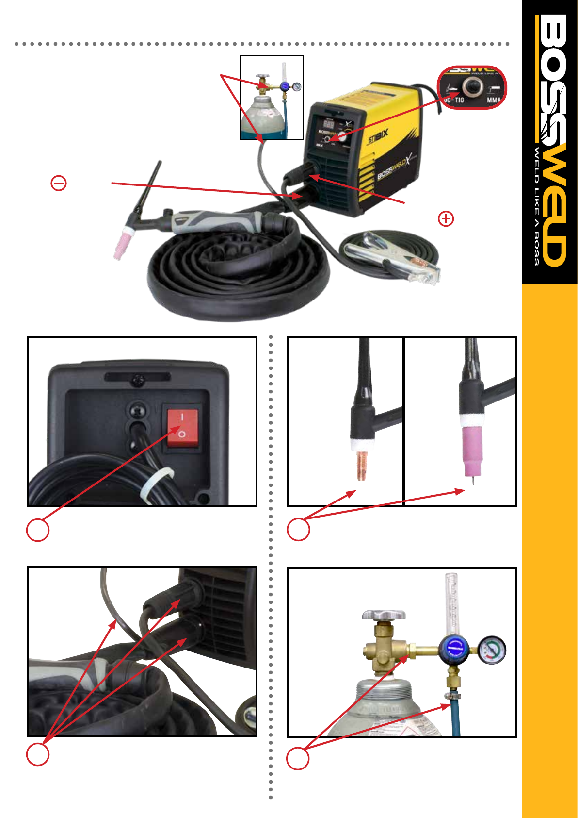
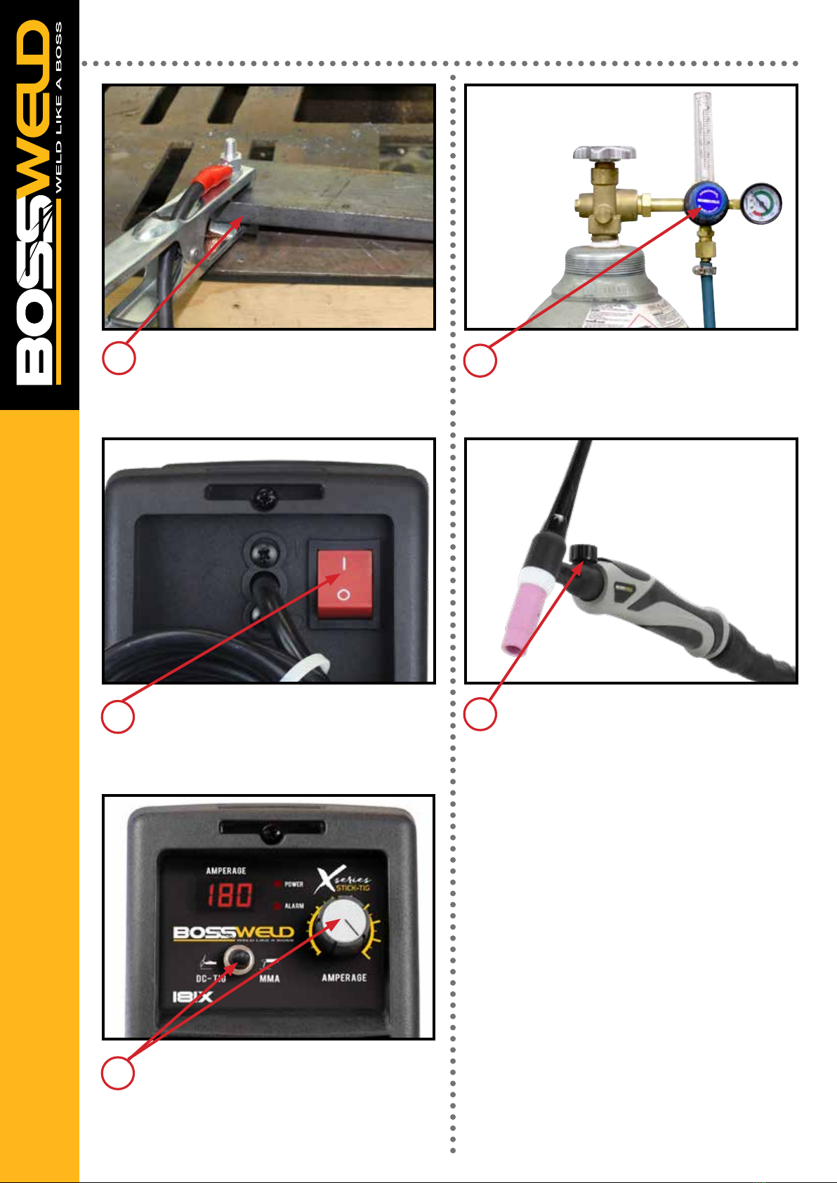
MACHINE SET UP TIG WELD
7.Select TIG
2. Connect TIG Torch
to the terminal
5. Connect earth Clamp
to the terminal
4. Connect the Argon Gas Regulator
to the Gas bottle and connect the Gas Hose
from the torch to the Input socket on the
Regulator. Ensure the Gas regulator is in the
off position.
Plug the machine 10Amp (EVO 141) or 15Amp
(ST 181X) input power lead into the wall socket,
e
nsuring that the power switch on the machine
is in the OFF position.
1
Connect the Argon Gas Regulator to the Gas
bottle and connect the Gas Hose to the Gas
Input socket from the torch to the Regulator.
Ensure the Gas regulator is in the off position.
4
Install the TIG Torch to the machine
by connecting the Dinse Connector to the
Negative Output Connection Socket , the Gas
hose to the regulator and the TIG Torch
Control Socket and screw the nut up rmly.
2
Set up the TIG torch. Place the Tungsten
Electrode into the torch head and ensure back
cap and collet body are screwed in rmly.
3
NOTE: TIG Torch option and regulator shown are not supplied with the machine.
Note: Pictures may vary from your machine model
16
Select DC-TIG, Select your required current
by turning the Welding Parameter Adjustment
Knob.
Turn the machine on using the mains power
switch. The front displays will light up and the
cooling fan will start.
6
7
Connect earth clampto the positive terminal
and rmly to work-piece ensuring that the
clamp makes good contact with bare metal.
5
MACHINE SET UP TIG WELD - CONTINUED
Note: Pictures may vary from your machine model
Turn on regulator and set gas ow to between
10-15 L/min depending on your welding
environment.
Turn the valve on the torch head to start the
ow of gas, Remember to turn it off when
nished welding.
8
9
IMPORTANT! -
We strongly recommend that you check for gas
leakage prior to operation of your machine. We
recommend that you close the cylinder valve when
the machine is not in use. BOSSWELD authorised
representatives or agents of BOSSWELD will not be
liable or responsible for the loss of any gas.
Note: It is advisable to run a few test welds using
scrap or offcut materials, in order to tune the
machine to the correct settings prior to welding
the job.

17
Note: Pictures may vary from your machine model
LIFT ARC START
With a small movement rotate the Gas Cup
forward so that the Tungsten Electrode touch-
es the work piece.
Press the button on the TIG torch Now rotate the Gas Cup in the reverse
direction to lift the Tungsten electrode from the
work piece to create the arc.
3
24
Lay the outside edge of the Gas Cup on the
work piece with the Tungsten Electrode
1- 2mm from the work piece.
1

18
BACK CAP
INSULATOR
COLLET
COLLET BODY
GAS LENS ALUMINA CUP
ALUMINA CUP
TORCH BODY
GAS LENS COLLET BODY
PART NO. DESCRIPTION
95.17FV.4.1.DA50 Tig Torch 17 Valve, 4mt, 1 pc, Dinse 50
BOSSWELD 17 SERIES 150AMP TIG TORCH COMPLETE
PART NO. DESCRIPTION
9957Y04 Back Cap Short
9557Y05 Back Cap Medium
955Y02 Back Cap Long
PART NO. DESCRIPTION
9518CG Torch Body Front Insulator
9554N01 Torch Body Front Insulator Lens Cup
PART NO. DESCRIPTION
9510N21 Collet 0.5mm
9510N22 Collet 1.0mm
9510N23 Collet 1.6mm
9510N24 Collet 2.4mm
9510N25 Collet 3.2mm
9510N20 Collet 4.0mm
PART NO. DESCRIPTION
9510N29 Collet Body 0.5mm
9510N30 Collet Body 1.0mm
9510N31 Collet Body 1.6mm
9510N32 Collet Body 2.4mm
9510N28 Collet Body 3.2mm
95406488 Collet Body 4.0mm
PART NO. DESCRIPTION
9510N50 Alumin Cup Size 4
9510N49 Alumin Cup Size 5
9510N48 Alumin Cup Size 6
9510N47 Alumin Cup Size 7
9510N46 Alumin Cup Size 8
9510N45 Alumin Cup Size 10
9510N44 Alumin Cup Size 12
PART NO. DESCRIPTION
9545V24 Gas Lens Collet 1.0mm
9545V25 Gas Lens Collet 1.6mm
9545V26 Gas Lens Collet 2.4mm
9545V27 Gas Lens Collet 3.2mm
9545V28 Gas Lens Collet 4.0mm
PART NO. DESCRIPTION
9554N18 Gas Len Alumin Cup Size 4 - 6.0mm
9554N17 Gas Len Alumin Cup Size 5 - 8.0mm
9554N16 Gas Len Alumin Cup Size 6 - 9.5mm
9554N15 Gas Len Alumin Cup Size 7 - 11.0mm
9554N14 Gas Len Alumin Cup Size 8 - 12.7mm
9554N19 Gas Len Alumin Cup Size 11 - 17.5mm
PART NO. DESCRIPTION
954WP26V Torch Head with Valve
95WP26FV Flex Torch Head with Valve
19
TIG WELDING
Tungsten inert gas (TIG) welding became an overnight success in the 1940s for joining magnesium and
aluminium. Using an inert gas shield instead of a slag to protect the weldpool, the process was a highly
attractive replacement for gas and manual metal arc welding. TIG has played a major role in the acceptance
of aluminium for high quality welding and structural applications.
PROCESS CHARACTERISTICS
In the TIG process the arc is formed between a pointed tungsten electrode and the workpiece in an inert
atmosphere of argon or helium. The small intense arc provided by the pointed electrode is ideal for high
quality and precision welding. Because the electrode is not consumed during welding, the welder does not
have to balance the heat input from the arc as the metal is deposited from the melting electrode. When ller
metal is required, it must be added separately to the weldpool.
POWER SOURCE
TIG must be operated with a constant current power source - either DC or AC. A constant current power
source is essential to avoid excessively high currents being drawn when the electrode is short-circuited onto
the workpiece surface. This could happen either deliberately during arc starting or inadvertently during
welding. If, as in MIG welding, a at characteristic power source is used, any contact with the workpiece
surface would damage the electrode tip or fuse the electrode to the workpiece surface. In DC, because arc
heat is distributed approximately one- third at the cathode (negative) and two-thirds at the anode (positive),
the electrode is always negative polarity to prevent overheating and melting. However, the alternative power
source connection of DC electrode positive polarity has the advantage in that when the cathode is on the
workpiece, the surface is cleaned of oxide contamination. For this reason, AC is used when welding
materials with a tenacious surface oxide lm, such as aluminium.
ARC STARTING
The welding arc can be started by scratching the surface, forming a short-circuit. It is only when the
short-circuit is broken that the main welding current will ow. However, there is a risk that the electrode may
stick to the surface and cause a tungsten inclusion in the weld.
TUNGSTEN SELECTION / PREPARATION & GRINDING
ELECTRODES
Electrodes for DC welding are normally pure tungsten with 1 to 4% thoria to improve arc ignition. Alternative
additives are lanthanum oxide and cerium oxide which are claimed to give superior performance (arc starting
and lower electrode consumption). It is important to select the correct electrode diameter and tip angle for
the level of welding current. As a rule, the lower the current the smaller the electrode diameter and tip angle.
In AC welding, as the electrode will be operating at a much higher temperature, tungsten with a zirconia
addition is used to reduce electrode erosion. It should be noted that because of the large amount of heat
generated at the electrode, it is difcult to maintain a pointed tip and the end of the electrode assumes a
spherical or ‘ball’ prole.
Grinding creates the greatest hazard as the exposed tungsten/thoria area is greatly increased and ne
particles of potentially radioactive dust are released into the atmosphere. It is recommended that a dedicated
grindstone with local dust extraction is used, and a simple lter mask is worn. If the grinding wheel is not
tted with a protective viewing screen, eye protection must be worn.
TRIGGER
WELDING WIRE
FLUX COATING
ROD
ARC
CONTACT TIP
DROPLETS
SHIELDING GAS
ARC
MOLTEN WELD METAL
SHROUD
WORK PIECE WORK PIECE
WORK PIECE WORK PIECEWORK PIECE WORK PIECE
WORK PIECE WORK PIECE
STRAIGHT GROUND
CORRECT PREPERATION - STABLE ARC INCORRECT PREPERATION - STABLE ARC
RADIAL GROUND
ARC WANDER
TUNGSTEN ELECTRODE
GAS LENS
STABLE ARC
FLAT TIP POINTED TIP
GRINDING WHEELGRINDING WHEEL
FILLER WIRE
Note: Do not use wheel for other jobs or tugsten can become contaminated and cause lower weld quality
20
TIG WELDING - CONTINUED
This risk can be minimised using the ‘lift arc’ technique where the short-circuit is formed at a very low
current level. The most common way of starting the TIG arc is to use HF (High Frequency). HF consists of
high voltage sparks of several thousand volts which last for a few microseconds. The HF sparks will cause
the electrode - workpiece gap to break down or ionise. Once an electron/ion cloud is formed, current can ow
from the power source.
Note: As HF generates abnormally high electromagnetic emission (EM), welders should be aware that its
use can cause interference especially in electronic equipment. As EM emission can be airborne, like radio
waves, or transmitted along power cables, care must be taken to avoid interference with control systems and
instruments in the vicinity of welding.
HF is also important in stabilising the AC arc; in AC, electrode polarity is reversed at a frequency of about 50
times per second, causing the arc to be extinguished at each polarity change. To ensure that the arc is
reignited at each reversal of polarity, HF sparks are generated across the electrode/workpiece gap to
coincide with the beginning of each half-cycle.
APPLICATIONS
TIG is applied in all industrial sectors but is especially suitable for high quality welding. In manual welding,
the relatively small arc is ideal for thin sheet material or controlled penetration (in the root run of pipe welds).
Because deposition rate can be quite low (using a separate ller rod) MMA or MIG may be preferable for
thicker material and for ll passes in thick-wall pipe welds.
TIG is also widely applied in mechanised systems either autogenously or with ller wire. However, several
‘off the shelf’ systems are available for orbital welding of pipes, used in the manufacture of chemical plant or
boilers. The systems require no manipulative skill, but the operator must be well trained. Because the welder
has less control over arc and weldpool behaviour, careful attention must be paid to edge preparation
(machined rather than hand-prepared), joint t-up and control of welding parameters.
T
TIG
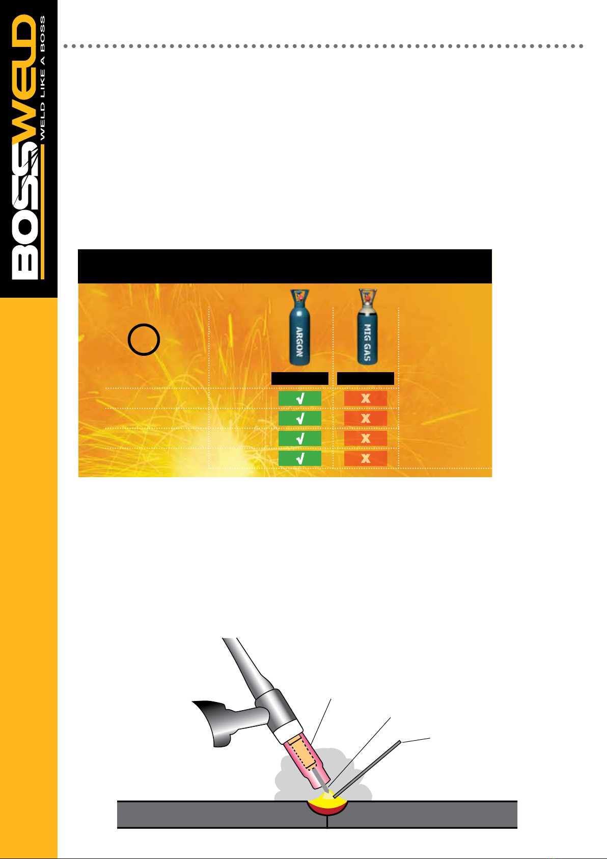
X
X
X
X
√
√
√
√
TIG WELDING
MILD STEEL
STAINLESS STEEL
LOW ALLOY STEEL
ALUMINIUM
ARGON Ar-CO2-O2
WELDING GAS SELECTION CHART GUIDE
TRIGGER
WELDING WIRE
FLUX COATING
ROD
ARC
CONTACT TIP
DROPLETS
SHIELDING GAS
ARC
MOLTEN WELD METAL
SHROUD
WORK PIECE WORK PIECE
WORK PIECE WORK PIECEWORK PIECE WORK PIECE
WORK PIECE WORK PIECE
STRAIGHT GROUND
CORRECT PREPERATION - STABLE ARC INCORRECT PREPERATION - STABLE ARC
RADIAL GROUND
ARC WANDER
TUNGSTEN ELECTRODE
GAS LENS
STABLE ARC
FLAT TIP POINTED TIP
GRINDING WHEELGRINDING WHEEL
FILLER WIRE
Note: Do not use wheel for other jobs or tugsten can become contaminated and cause lower weld quality
This manual suits for next models
2
Table of contents
Popular Inverter manuals by other brands


BARRON
BARRON EXITRONIX Tucson Micro Series installation instructions

Baumer
Baumer HUBNER TDP 0,2 Series Mounting and operating instructions

electroil
electroil ITTPD11W-RS-BC Operation and Maintenance Handbook

Silicon Solar
Silicon Solar TPS555-1230 instruction manual

Mission Critical
Mission Critical Xantrex Freedom SW-RVC owner's guide

HP
HP 3312A Operating and service manual


