BossWeld MST185 User manual

INVERTER
MIG/TIG/STICK
WELDER
MANUAL
MST185
2
YEAR
LIMITED
WARRANTY
10AMP
PLUG

2
Thank you for choosing a BOSSWELD MST185 Inverter DC MIG Welder
In this manual you will nd instructions on how to set up your welder along with general welding information,
safety information and helpful tips. We encourage you to go online to our website for more tips and
troubleshooting as well as many welding resources. www.bossweld.com.au
The BOSSWELD MST185 is the latest in IGBT welder technology, this lightweight multipurpose welder is very
simple to set up and operate enabling the user to complete high quality welds in MIG Gas / Gasless and
MMA / Stick electrode as well as DC TIG processes. A great all round welder for the serious tradesman that
wants to take on bigger welding projects.
Every effort has been made to ensure that this manual has been prepared accurately, however errors and omissions are excepted.
BOSSWELD is a trademark of Dynaweld Industrial Supplies Pty Ltd.
MMIG
• Simple to learn
• MIG Wire is fed through the gun to create the weld pool
• Gas or flux prevents oxidisation in the weld
• Weld with or without gas
• Point and pull the trigger
• Great for maintenance, small projects
& automotive repairs
METAL TYPES
Mild steel, stainless steel & aluminium
SSTICK
• Easiest process to learn
• Best choice for quick repairs
• Slower than MIG welding
• Forgiving in dirty/rusty environments
• Not recommended for thin sheet metal welding
METAL TYPES
Mild steel, stainless steel & cast iron
TTIG
• Gives a better weld finish
• Accurate heat control
• Considered the most challenging process to learn
• Good way to weld thin material
• Argon gas is required
METAL TYPES
Mild steel, stainless steel & aluminium
PPLASMA CUTTING P
• Wide range of uses to cut conductive metals
• Uses an accelerated jet of hot plasma
• High speed/low cost cutting method
• Used extensively replacing gas cutting methods
• Air compressor is required
METAL TYPES
Mild steel, stainless steel & aluminium

3
CONTENTS PAGE
WARRANTY 4
BOX CONTENTS 5
WARNINGS 6
MACHINE CARE / SAFETY INSTRUCTIONS 7
WORK AREA SAFETY 8
MAINTENANCE & DISPOSAL / GAS BOTTLE 9
FRONT & REAR PANEL LAYOUT 10
MACHINE CONTROLS PANEL 11
MACHINE INSIDE 12
WIRE SPOOL & WIRE FEED SET UP 13
MIG TORCH SETUP 14
LINER INSTALLATION / REPLACEMENT 15
DRIVE ROLLER SIZE 16
2T / 4T TRIGGER CONTROL INFORMATION 16
LIFT ARC START 17
MIG TORCH AND CONSUMABLE CARE 18
STICK / MMA WELDING SETUP 19-20
GENERAL MMA WELDING 21
GASLESS MIG WELDING SETUP 22-24
GAS MIG WELDING SETUP 24-27
GENERAL MIG WELDING 28-31
TIG WELDING SETUP 32-33
TUNGSTEN PREPARATION 34
GENERAL TIG WELDING 35
BZ15 MIG TORCH PARTS BREAK DOWN 36
17 SERIES TIG TORCH BREAKDOWN 37
HELPFUL INFORMATION & TROUBLE SHOOTING 38-41
WELDING CONSUMABLE / ACCESSORIES 42-43

4
WARRANTY
This warranty is in addition to the statutory warranty provided under Australian Consumer Law, but does not
include damage resulting from transport, misuse, neglect or if the product has been tampered with.
The product must be maintained as per this manual, and installed and used according to these instructions on
an appropriate power supply. The product must be used in accordance with industry standards and acceptable
practice.
Special note:
If this welders duty cycle is exceeded the welder will enter “thermal overload” which will automatically
stop the welding output in order to protect, both the user and the welder. You will know the welder has
gone into thermal overload when the thermal overload light is illuminated. The welder will then cool
itself down, and once the thermal overload indicator light is no longer illuminated, welding can then
re-commence.
Please note. Exceeding the machine’s duty cycle, cannot be considered grounds for warranty or return.
This warranty covers the materials used to manufacture the machine and the workmanship used to produce the
item. This Warranty does not cover damage caused by:
1. Normal wear and tear due to usage
2. Misuse /abuse or Neglect of the item
3. Transport / handling breakages
4. Lack of maintenance, care and cleaning
5. Environmental factors, such as usage in temperatures exceeding 40 degrees, above 1000mt sea level, rain,
water, excessive damp, cold or humid conditions.
6. Improper setup or installation
7. Use on Incorrect voltage or non authorised electrical connections and plugs
8. Use of non standard parts
9. Repair, case opening, tampering with, modications to any part of the item by non authorised BOSSWELD
repairers.
This warranty covers the machine only and does not include Torches, Leads, Earth Clamps, Electrode holders,
Plasma Torches, Tig Torches and any of the parts on those items unless there is a manufacturing fault.
1. REGISTRATION
Purchasers are encouraged to register for warranty on our website. www.bossweld.com.au/warranty
2. TIME PERIOD - 2 Years
A warranty claim must be made within 2 years from the date of purchase of this product. Any claim must include
proof of purchase.
3. HOW TO MAKE A CLAIM - NEED SOME HELP?
• Visit our website www.bossweld.com.au/troubleshooting for many helpful tips and guides to assist with the
setup and usage of your new machine. Still stuck….?
• Call the BOSSWELD Helpdesk on 1300 899 710 for over the phone assistance.
• Visit www.bossweld.com.au.
• If the machine is not operational then return the item to the place of purchase.
BOSSWELD MAKES NO OTHER WARRANTY, EXPRESS OR IMPLIED. THIS WARRANTY IS EXCLUSIVE
AND IN LIEU OF ALL OTHERS, INCLUDING, BUT NOT LIMITED TO ANY WARRANTY OF
MERCHANTABILITY OR FITNESS FOR ANY PARTICULAR PURPOSE.
2
YEAR
LIMITED
WARRANTY

5
BOSSWELD MST185 Inverter DC MIG Welder Box Contents
1. BOSSWELD MST185 Inverter MIG/MMA/TIG Welder
2. 3 metre 15 Series MIG Torch
3. Electrode Holder Lead
4. Welding Earth Lead
5. Gas Hose
6. Dual Stage Argon Regulator
7. Torch Spares
8. Drive Roller (Installed in Machine 0.8-0.9 V Groove) - not shown.
Gasless Drive Roller 0.8/0.9mm (Spare Drive Roller) - not shown.
9. Owners Manual -not shown.
1
2
3
4
5
6
7

6
The device and packaging material are not toys! Children must not be allowed to play with the machine and its
accessories. Plastic parts and packaging are choking risks for children.
• Open the packaging and remove the welder carefully.
• Check that the delivery is complete.
• If possible, store the packaging until the warranty period has expired.
PERSONAL PROTECTIVE EQUIPMENT (PPE)
GLOVES AND PROTECTIVE CLOTHING
Use protective gloves and re resistant protective clothing when welding.
Avoid exposing skin to ultraviolet rays produced by the arc.
WELDING HELMET
Under no circumstances should the welder be operated unless the operator is wearing a
welding helmet to protect the eyes and face. There is serious risk of eye damage if a helmet is
not used. The sparks and metal projectiles can cause serious damage to the eyes and face.
The light radiation produced by the arc can cause damage to eyesight, and burns to skin.
Never remove the welding helmet whilst welding.
SAFETY GLASSES
After welding use appropriate safety glasses when brushing, chipping or grinding the slag from
the weld.
OTHER PERSONS
Ensure that other persons are screened from the welding arc and are at least 15 metres away
from the work piece. Always ensure that the welding arc is screened from onlookers, or people
just passing by. Use screens if necessary, or non-reecting welding curtain. Do not let children
or animals have access to the welding equipment or to the work area.
SWITCHING OFF
When the operator has nished welding they must switch the welder off.
DO NOT put the electrode holder down with the welder switched ON.
When leaving the welder unattended, move the ON/OFF switch to the OFF position and
disconnect the welder from the electrical mains supply.
Do not leave hot material unattended after welding.
FUMES &GASES ARE DANGEROUS
Smoke and gas generated whilst welding or cutting can be harmful to people’s health. Welding
produces fumes and gases. Breathing these fumes and gases can be hazardous to your health.
• Do not breathe the smoke and gas generated whilst welding or cutting, keep your head out of
the fumes
• Keep the working area well ventilated, use fume extraction or ventilation to remove welding
fumes and gases.
• In conned or heavy fume environments always wear an approved air-supplied respirator.
Welding fumes and gases can displace air and lower the oxygen level causing injury or
death. Be sure the breathing air is safe.
• Do not weld in locations near de-greasing, cleaning, or spraying operations.
The heat and rays of the arc can react with vapours to form highly toxic and irritating gases.
• Materials such as galvanized, lead, or cadmium plated steel, containing elements that can
give off toxic fumes when welded. Do not weld these materials unless the area is very well
ventilated, and or wearing an air supplied respirator.
WARNING

7
Keep the welding cables, earth clamp and electrode holder in good condition. Failure to do this can result in
poor welding quality, which could be dangerous in structural situations.
Prior to use, check for breakage of parts and any other conditions that may affect operation of the welder.
Any part of the welder that is damaged should be carefully checked to determine whether it will perform its
intended function whilst being safe for the operator. Any part that is damaged should be properly repaired, or
replaced by an authorised service centre.
IMPROPER USE
It is hazardous to use the welding machine for any work other than that for which it was designed e.g. do not
use welder for thawing pipes.
HANDLING
Ensure the handle is correctly tted. As welding machines can be heavy, always use safe lifting practices when
lifting.
POSITION AND HANDLING
To reduce risk of the machine being unstable / danger of overturning, position the welding machine on a
horizontal surface that is able to support the machine weight. Operators MUST NOT BE ALLOWED to weld in
raised positions unless safety platforms are used.
WARNING
The user of this welder is responsible for their own safety and the safety of others. It is important to read,
understand and respect the contents of this user guide. When using this welder, basic safety precautions,
including those in the following sections must be followed to reduce the risk of re, electric shock and personal
injury. Ensure that you have read and understood all of these instructions before using this welder.
Persons who are not familiar with this user guide should not use this welder. Keep this booklet in a safe place
for future reference.
TRAINING
The operator should be properly trained to use the welding machine safely and should be informed about the
risks relating to arc welding procedures. This user guide does not attempt to cover welding technique. Training
should be sought from qualied / experienced personnel on this aspect, especially for any welds requiring a high
level of integrity for safety.
SERIOUS FIRE RISK
The welding process produces sparks, droplets of fused metal, metal projectiles and fumes.
This constitutes a serious re risk. Ensure that the area in which welding will be undertaken is clear of all
inammable materials. It is also advisable to have a re extinguisher, and a welding blanket on hand to protect
work surfaces.
MACHINE CARE / SAFETY
SAFETY INSTRUCTIONS

8
Ensure a clear, well lit work area with unrestricted movement for the operator.
The work area should be well ventilated, as welding emits fumes which can be dangerous.
Always maintain easy access to the ON/OFF switch of the welder, and the electrical mains supply.
Do not expose the welder to rain and do not operate in damp or wet locations
WORK AREA
Where welding must be undertaken in environments with increased risk of electric shock, conned spaces or in
the presence of ammable or explosive materials, it is important that the environment be evaluated in advance
by an “expert supervisor”. It is also recommended that welding in these circumstances be carried out in the
presence of persons trained to intervene in emergencies.
AVOID ELECTRICAL CONTACT
Use adequate electrical insulation with regard to the electrode, the work piece and any accessible earthed metal
parts in the vicinity. Avoid direct contact with the welding circuit. The no load voltage between the earth clamp
and the electrode can be dangerous under certain circumstances.
Note: For additional protection from electric shock. It is recommended that this welder be used in conjunction
with a residual current device (RCD) with rated residual current of 30MA or less.
In general the use of extension leads should be avoided. If used however, ensure that the extension lead is
used with the welder is of a suitable current rating and heavy duty in nature that MUST have an earth
connection. If using the welder outdoors, ensure that the extension lead is suitable for outdoor use. Always keep
extension leads away from the welding zone, moisture and any hot materials.
WELDING SURFACES
Do not weld containers or pipes that hold, or have held, ammable liquids or combustible gases or pressure.
Do not weld on coated, painted or varnished surfaces as the coatings may ignite, or can give off dangerous
fumes.
WORK PIECE
When welding, the work piece will remain at high temperature for a relatively long period. The operator must not
touch the weld or the work piece unless wearing welding gloves. Always use pliers or tongs. Never touch the
welded material with bare hands until it has completely cooled.
VOLTAGE BETWEEN ELECTRODE HOLDERS OR TORCHES
Working with more than one welding machine on a single work piece, or on work pieces that are connected,
may generate a dangerous accumulation of no-load voltage between two different electrode holders or torches,
the value of which may reach double the allowed limit.

9
WARNING
Before starting any cleaning, or maintenance procedures on the welding machine, make sure that it is switched
OFF and disconnected from the mains supply.
There are no user serviceable parts inside the welder. Refer to a qualied service personnel if any internal
maintenance is required. After use, wipe the welder down with a clean soft dry cloth.
Regular inspection of the supply cord is required and if damaged is suspected, it must be immediately replaced
by the manufacturer, its service agent or similarly qualied persons in order to avoid a hazard
STORAGE/ TRANSPORT
Store the welder and accessories out of children’s reach in a dry place. If possible store the welder in the
original packaging. The appliance must unconditionally be secured against falling or rolling over during
transport.
DISPOSING OF THE PACKAGING
Recycling packaging reduces the need for landll and raw materials. Reuse of the recycled material
decreases pollution in the environment. Please recycle packaging where facilities exist. Check with your local
council authority for recycling advice.
DISPOSING OF THE WELDER
Welders that are no longer usable should not be disposed of with household waste but in an environmentally
friendly way. Please recycle where facilities exist. Check with your local council authority for recycling advice.
MAINTENANCE
DISPOSAL
GAS BOTTLE
ATTENTION! - CHECK FOR GAS LEAKS
At initial set up and at regular intervals we recommend to check for gas leakage
Recommended procedure is as follows:
1. Connect the regulator and gas hose assembly and tighten all connectors and clamps.
2. Slowly open the cylinder valve.
3. Set the ow rate on the regulator to approximately 10-15 l/min.
4. Close the cylinder valve and pay attention to the needle indicator of the contents pressure gauge on
the regulator, if the needle drops away towards zero there is a gas leak. Sometimes a gas leak can
be slow and to identify it will require leaving the gas pressure in the regulator and line for an extended
time period. In this situation it is recommended to open the cylinder valve, set the ow rate to 8-10 l/min,
close the cylinder valve and check after a minimum of 15 minutes. Ensuring adequate ventilation fore
small spaces.
5. If there is a gas loss then check all connectors and clamps for leakage by brushing or spraying with /
soapy water, bubbles will appear at the leakage point.
6. Tighten clamps or ttings to eliminate gas leakage.
IMPORTANT! - We strongly recommend that you check for gas leakage prior to operation of your
machine. We recommend that you close the cylinder valve when the machine is not in use.
BOSSWELD, authorised representatives or agents of BOSSWELD will not be liable or responsible for the
loss of any gas.

10
FRONT PANEL
1. Control Panel - See page 11
2. Euro Torch Connection Socket
3. Positive Output Connection Socket
4. Negative Output Connection Socket
5. Tig Torch Control Socket
6. Gas Output (for TIG process)
REAR PANEL
7. Mains Power Switch
8. Gas Input
Note: This machine has a Quick connect tting.
The Gas hose supplied has hose clamp tting,
optional quick connect upgrade available.
9. 240V AC Mains Power Cord
10. 10Amp Input Plug
11. Cooling Fan
6
4
1
2
7
11
5
8
3
9
10

11
CONTROL PANEL
1
2 4 6 7 11 12
3 5 8 9 13
10
14
1 Welding Method
Press to select MIG / MMA Stick / TIG
2 Welding Mode
• Press to select 2T or 4T
welding mode (MIG / TIG)
3 Current / wire feed speed Display
• Displays the Welding current in Amps.
(when 6 is lit) MMA
• Displays Wire Speed in Meters per Min
(when 5 is lit) MIG
4 Welding Current /
Wire Speed Adjustment Knob
• Set the Welding Current in Amps MMA / Lift TIG
• Set the Wire Speed in Meters per Minute
in MIG
5 Wire Speed LED
Use current setting knob to set the wire speed
(MIG)
6 Current LED
Illuminates when MIG current is active.
7 Welding Voltage / Arc Force /
Down slope Adjustment
• Set Welding Volts in MIG mode
• Adjust Arc Force in Stick / MMA mode
• Adjust the current down time in TIG mode
8 Voltage , Arc Force and Downslope Display
• Displays the Welding voltage when machine
is in MIG
• Displays the Arc Force when machine
is in Stick / MMA
• Displays the Downslope current down time
in TIG
9 Voltage LED
Illuminates when Voltage selection is on,
use Voltage setting knob to adjust voltage
10 ARC Force LED
When the Arc Force LED is on you can use
the voltage setting knob to set the
ARC Force (MMA)
11 Down Slope LED
Illuminates when Down Slope is on
12 Wave Control Knob
Controls the Arc characteristics (inductance)
13 Power LED
Illuminates when Power is on.
14 Overload Error Indicator
Illuminates when the machine is overloaded

12
A
B
G
D
F
I
H
C
E
SIDE PANEL (DOOR OPEN)
A. Spool Hub
B. Spool Hub Nut
C. Polarity Switching Terminal
D. Drive Roller
E. Drive Roller Retainer Nut
F. Wire Inlet
G. Wire Guide Inlet Tube
H. Wire Feed Tensioning Adjustment
I. Idle Roller / Wire Tensioning Arm
CC
DCEN
Polarity Switching Terminal
Set for Gasless Welding
DCEP
Polarity Switching Terminal
Set for Gas Welding
DCEN - GASLESS DCEP - GAS
SETTING MACHINE POLARITY

13
SET UP OF WIRE SPOOL & WIRE FEED UNIT
Open the side door of the machine.
Release the Wire Feed Tensioning
Knob by pulling it to the left.
Take the end of the wire and feed
into the Guide tube until it passes to
the Inlet Tube, and out of the Euro
connection Approx 3-5cm
Remove the Spool Hub Nut and
place spool of wire on Spool Hub.
Note: Wire to roll from under spool
into wire feeder
Remove the Drive Roller Cover. Check
the Drive roller is matched to the wire
size for the job Note: Correct wire side
on roller to face into machine when
tting. Then replace the Drive Roller
Cover.
See Page 16 for drive roller
size and type.
Put down Wire Tensioning Arm so it
locks into position, and turn the Wire
Feed Tensioning Knob to gently
tighten.
Replace Spool Hub Nut and adjust
rmly - without too much pressure.
Note: Pictures may vary from your machine model
Ensure you hold the spool and check
tension to stop wire spool unraveling
15
2
3
4
7
6
Roller Groove
V Groove - Mild Steel
U Groove - Aluminium
V-knurled - Gasless Wire
Drive roller
size (mm)

14
SET UP OF MIG TORCH
Press the trigger. This will feed the
wire through the torch.
Release button when wire
appears at the end of the torch.
Plug machine into 240V and
switch to the ON position on the
back of machine.
Trim wire to the end of the nozzle.
Attach the Euro Connect MIG
torch to the machine feeding the
wire into the liner.
Tighten MIG Torch connector to
machine.
Remove nozzle (A) and
tip (B) from torch.
A
B
Re install tip over the wire and tight-
en using the tool supplied, Do NOT
over tighten, or you may damage the
tip holder and re-attach nozzle to
torch.
Note: Pictures may vary from your machine model
1
3
5
7
6
4
2

15
Re install tip and tighten
using the tool provided
and re attach nozzle to
torch. Do NOT over
tighten, or you may
damage the tip holder
MIG TORCH LINER INSTALLATION / REPLACEMENT
Lay the MIG torch out
straight and at on the
ground and remove the
front end parts
Carefully feed the new
liner into the torch lead all
the way out the end of the
torch
Remove the liner retaining
nut from the euro torch
end.
Fit the retaining nut and
slightly tighten the nut
about half way
Snip the new liner 3mm
past the end of the torch
neck
Tighten the retaining nut
up all the way.
Carefully remove the liner
completely from the torch.
PART NO. DESCRIPTION ORIGINAL REF
92.04.B3 Blue steel liner 0.6 - 0.8mm 3mt 124.0011
92.04.B4 Blue steel liner 0.6 - 0.8mm 4mt 124.0012
92.04.B5 Blue steel liner 0.6 - 0.8mm 5mt 124.0015
92.04.R3 Red steel liner 0.9 - 1.2mm 3mt 124.0026
92.04.R4 Red steel liner 0.9 - 1.2mm 4mt 124.0031
92.04.R5 Red steel liner 0.9 - 1.2mm 5mt 124.0035
92.04.BT3 Blue teflon liner 0.6 - 0.9mm 3mt 126.0005
92.04.BT4 Blue teflon liner 0.6 - 0.9mm 4mt 126.0008
92.04.RT3 Red teflon liner0.9 - 1.2mm 3mt 124.0011
92.04.RT4 Red teflon liner0.9 - 1.2mm 4mt 124.0012
92.04.RT5 Red teflon liner0.9 - 1.2mm 5mt 124.0015
Steel Liners
Teflon Liners for Aluminium
Note: Pictures may vary from your machine model
147
25
36
8

16
MACHINE DRIVE ROLLER SIZE (NOTE: MACHINE WILL RUN UP TO 0.9MM WIRE)
30mm
10mm
10mm
*Denotes driver rollers supplies with machine
PART NO. DESCRIPTION
Knurled Drive Roller For Gasless Wire
RK301010.08.09 *Drive Roller 0.8/0.9mm Knurled 30 x 10 x 10mm
U Grooved Drive Roller For Aluminium Wire
RU301010.06.08 Drive Roller 0.6/0.8mm U Groove 30 x 10 x 10mm
RU301010.09.12 Drive Roller 0.9/1.2mm U Groove 30 x 10x 10mm
V Grooved Drive Roller For Solid Wire
RV301010.08.09 *Drive Roller 0.8/0.9mm V Groove 30 x 10 x 10mm
RV301010.08.10 Drive Roller 0.8/1.0mm V Groove 30 x 10 x 10mm
RV301010.09.12 Drive Roller 0.9/1.2mm V Groove 30 x 10 x 10mm
DUTY CYCLE:
Special note:
If this welders duty cycle is exceeded the welder will enter “thermal overload” which will
automatically stop the welding output in order to protect, both the user and the welder. You will know
the welder has gone into thermal overload when the thermal overload light is illuminated.
The welder will then cool itself down, and once the thermal overload indicator light is no longer
illuminated, welding can then re-commence.
Please note. Exceeding the machine’s duty cycle, cannot be considered grounds for warranty or
return.
The term duty cycle indicates the percentage welding time available at the output current for each 10 min
period over 4 hours,
The specication plate on the machine list three given ratings at a given current and voltage.
NOTE MIG SETTINGS SHOW BELOW : Amps refer to the Current setting
7% 60% 100%
180 - Amps 65-Amps 50-Amps
23.0 Volts 17.3 Volts 16.5 Volts
For example this means when the machine is set at is highest current of 180 Amps it can only weld for 42
seconds in a Ten minute period. The power source is protected by a built in temperature protection device,
This will activate if the machine is operated in excess of its amperage and duty cycle rating.
10
75 60
240
240
21
240
BOSSWELD MST185
610150
IEC 60794
Duty Cycle
Amperage / Current
Voltage
Amperage and
Voltage display
This light indicates
Over temperature / Duty cycle exceeded

17
2T / 4T TRIGGER CONTROL
2T Trigger Control
1. Press the trigger and Hold
2. The set pre-gas ow starts and the arc starts and will upslope to the amperage selected on
the amperage dial.
3. When you want to nish the weld, release the trigger and the amperage will begin to downslope at the rate
you have selected on the downslope dial, If you selected zero the arc will stop as soon as you release the
trigger.
4T Trigger Control
1. Press the trigger and Hold
2. The set preow gas starts and the arc starts.
3. Release the trigger and the amperage will upslope to the amperage selected on the amperage dial
4. When you want to nish the weld, press and hold the trigger and the amperage will begin to downslope
at the rate you have selected on the downslope dial, amperage will remain at this level until you release
the trigger.
5. Once you have released the trigger the arc will stop and the postow gas will continue for a pre set
amount of time
LIFT ARC START
Note: Pictures may vary from your machine model
Lay the outside edge of the Gas Cup on the
work piece with the Tungsten Electrode
1- 2mm from the work piece.
With a small movement rotate the Gas Cup
forward so that the Tungsten Electrode
touches the work piece.
Press the button on the TIG torch Now rotate the Gas Cup in the reverse
direction to lift the Tungsten electrode from the
work piece to create the arc.
13
24
*Denotes driver rollers supplies with machine
PART NO. DESCRIPTION
Knurled Drive Roller For Gasless Wire
RK301010.08.09 *Drive Roller 0.8/0.9mm Knurled 30 x 10 x 10mm
U Grooved Drive Roller For Aluminium Wire
RU301010.06.08 Drive Roller 0.6/0.8mm U Groove 30 x 10 x 10mm
RU301010.09.12 Drive Roller 0.9/1.2mm U Groove 30 x 10x 10mm
V Grooved Drive Roller For Solid Wire
RV301010.08.09 *Drive Roller 0.8/0.9mm V Groove 30 x 10 x 10mm
RV301010.08.10 Drive Roller 0.8/1.0mm V Groove 30 x 10 x 10mm
RV301010.09.12 Drive Roller 0.9/1.2mm V Groove 30 x 10 x 10mm

18
WELDING PRODUCTS TO HELP PROLONG, MAINTAIN
AND PRODUCE BETTER WELDS
Bossweld Aerosol Anti Spatter Spray (Part No: 800041)
This silicon free spatter release coating is a colourless
lm which stops weld spatter from sticking to welding equipment,
work pieces & xtures. Easily removed before painting or nishing.
Bossweld Tip Dip Gel (Part No: 800055)
Non toxic water based dipping gel for the prevention
of weld spatter adherence to MIG torch parts.
This silicon free compound is used to prolong
the life of nozzles & tips.
Bossweld 8 Ways MIG Welding Pliers (Part No: 800074)
Handy 8 function welders pliers. Functions include,
nozzle removal, tip removal, cleaning inside of nozzle
and wire cutting.
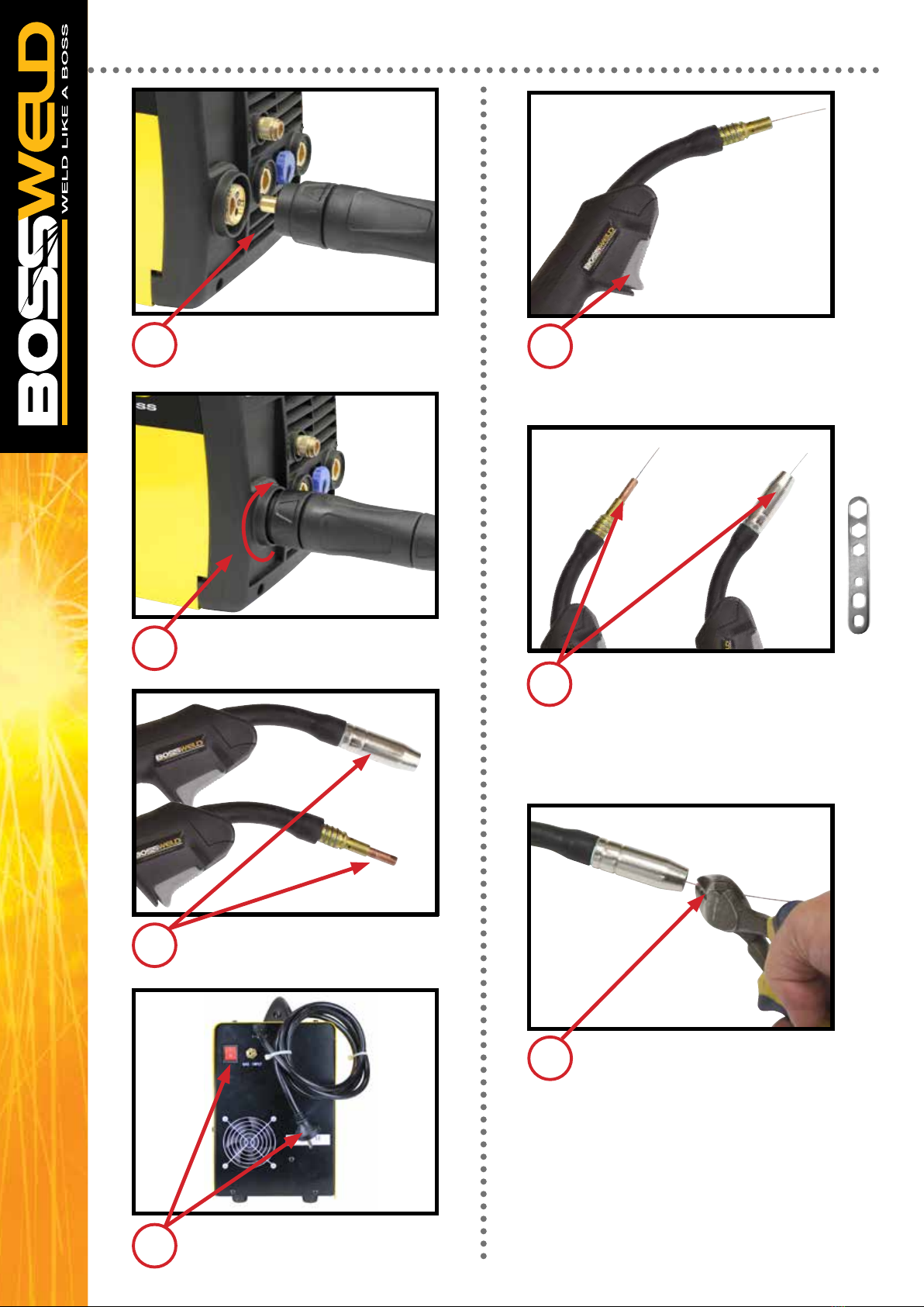
Proper MIG Torch inspection
Prior to welding, ensure all connections are tight and that consumables and equipment are in good condition
and free from damage. Start with the front of the gun and work your way back to the feeder. A tight neck
connection is essential to carry the electrical current from the welding cable to the front-end consumables.
Also, be sure to visually inspect the handle and trigger to check there are no missing screws or damage.
The cable should be free of cuts, kinks and damage along the outer cover. Cuts in the cable can expose the
internal copper wiring and create a potential safety hazard to the welding operator. In addition, these issues
can lead to electrical resistance that causes heat buildup — and ultimately cable failure.
Consumables
MIG gun front-end consumables are exposed to heat and spatter and therefore often require frequent
replacement. However, performing some simple maintenance can help extend consumable life and improve
gun performance and weld quality. The gas diffuser provides gas ow to the weld pool and also connects to
the neck and carries the electrical current to the contact tip. Make sure all connections are tight, and check
the diffuser’s O-rings for cracks, cuts or damage. The nozzle’s main role is to focus the shielding gas around
the weld pool. Watch for spatter buildup in the nozzle, which can obstruct gas ow and lead to problems
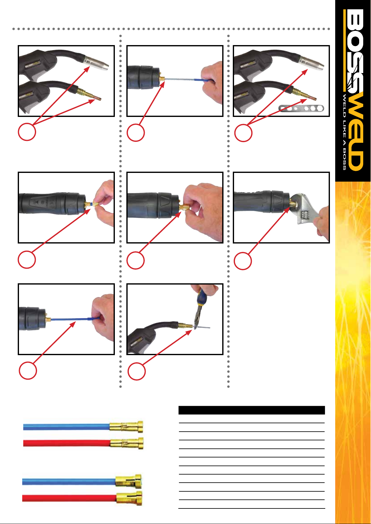
due to inadequate shielding coverage. Use MIG pliers to clean spatter from the nozzle. The contact tip is
the last point of contact between the welding equipment and the welding wire. Keyholing of the contact tip
is a concern to watch for with this consumable. This occurs when the wire passing through the tip wears an
oblong-shaped slot into the diameter of the tip. Keyholing can put the wire out of center and cause problems
such as an erratic arc. If you are experiencing wire feeding issues, try changing the contact tip or switching to
a larger-size contact tip. Tips that look worn should be replaced.
Final thoughts
Taking the time for preventative maintenance can pay off in less downtime in the long run. Along with that,
always remember to properly store your MIG gun consumables to help you achieve the best results and
extend the life of your equipment. When not in use, the MIG gun should be stored in a coiled position, either
hanging or lying at, such as on a shelf. Do not leave MIG gun on the oor of the shop, where there is a
chance the cable could be run over, kinked or damaged.
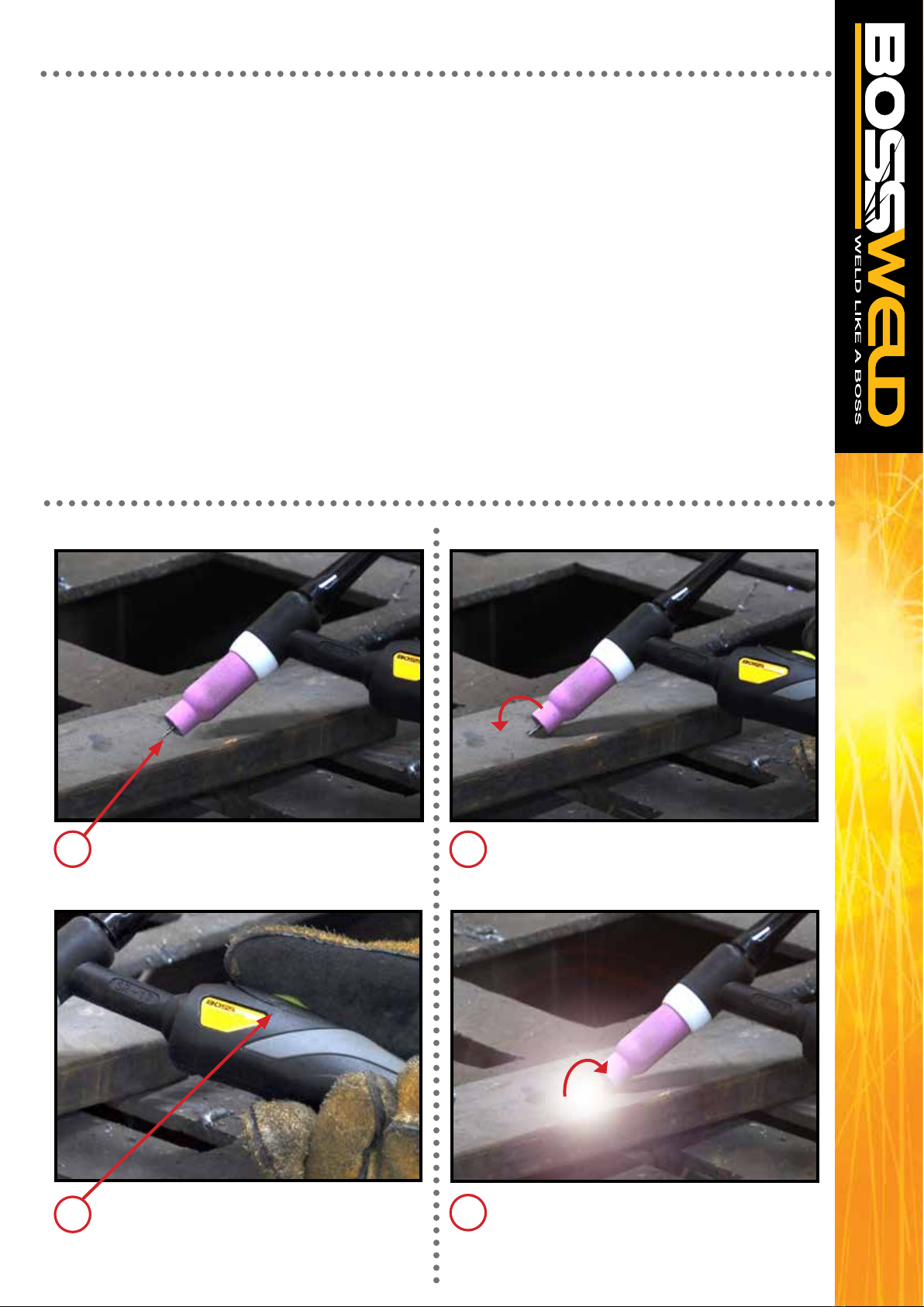
Spatter removal from inside and outside the nozzle using MIG pliers
Build up of spatter can
cause damage to
nozzle and tip
Keyholing of the
contact tip

19
MACHINE SET UP STICK/MMA
6.Select Stick / MMA mode
3. Connect earth Clamp
to the terminal
2. Connect Electrode holder
to the terminal
Note: The below image shows setup for DCEP / Negative Polarity
(Most Common application)
Plug the machine 10Amp input power lead into
the wall socket, e
nsuring that the power
switch on the machine is in the OFF position.
Connect earth clamp rmly to work-piece
ensuring that the clamp makes good contact
with bare metal.
Assemble Arc and Earth leads into the
welding terminals depending on requirements
of electrodes. Refer to your electrode packet
for polarity and current requirements.
• DCEP/ Negative Polarity (most common application)
- Earth clamp connector into the negative terminal.
- Electrode holder connector into the positive terminal.
•DCEN/Straight Polarity
- Earth clamp connector into the Positive terminal.
- Electrode holder connector into the Negative terminal.
Take electrode holder and press handle to
open the tong. Insert bare metal rod end of
electrode and release handle to clamp
electrode.
13
24
Note: Pictures may vary from your machine model

20
MACHINE SET UP STICK/MMA - CONTINUED
Select Stick / MMA on Welding Output Mode
Switch.
Ensure the electrode/electrode holder is not
near the work-piece or can earth out, turn the
machine on using the mains power switch.
The front displays will light up and the cooling
fan will start.
You can adjust the Arc force by using voltage
Parameter adjustment knob.
5 8
6
Select your required current by turning the
Welding Parameter Adjustment Knob.
Please see table on page 21 as a guide to
Welding Parameters.
7
9
Amperage Selection Guide
Rod Size/ Gauge Welding Current
1.6mm 40-50 Amps
2.0mm 50-75 Amps
2.5mm 75-105 Amps
3.2mm 105-140 Amps
4.0mm 140-160 Amps
Average Metal Thickness Electrode Size
1.0 - 2.0mm 2.0mm
2.0 - 5.0mm 2.6mm
5.0 - 8mm 3.2mm
8.0mm + 4.0mm
Table of contents
Other BossWeld Welding System manuals

BossWeld
BossWeld MST X250 PFC User manual

BossWeld
BossWeld M150 User manual

BossWeld
BossWeld MST X250 PFC User manual

BossWeld
BossWeld 200X User manual

BossWeld
BossWeld X Series User manual

BossWeld
BossWeld X Series User manual

BossWeld
BossWeld S140 User manual

BossWeld
BossWeld MST195 User manual

BossWeld
BossWeld Buddy MIG 150 User manual

BossWeld
BossWeld M100 User manual
Popular Welding System manuals by other brands

Sunkko
Sunkko 737G instruction manual

ESAB
ESAB Caddy Tig 1500i VRD instruction manual

Soyer
Soyer BMS-9 ACCU operating instructions

HURNER
HURNER CNC ECO 160 user manual

Chicago Electric
Chicago Electric 45690 Assembly and operating instructions

Lincoln Electric
Lincoln Electric HOT ROD 500S Operator's manual