14 15
MANUAL METAL ARC PROCESS (MMA WELDING)
When an arc is struck between the metal rod (electrode) and the workpiece, both the rod and workpiece
surface melt to form a weld pool. Simultaneous melting of the ux coating on the rod will form gas and slag
which protects the weld pool from the surrounding atmosphere. The slag will solidify and cool and must be
chipped off the weld bead once the weld run is complete (or before the next weld pass is deposited).
The process allows only short lengths of weld to be produced before a new electrode needs to be inserted in
the holder. Weld penetration is low and the quality of the weld deposit is highly dependent on the
skill of the welder.
TYPES OF ELECTRODES
Arc stability, depth of penetration, metal deposition rate and positional capability are greatly inuenced by the
chemical composition of the ux coating on the electrode. There are many types of Electrodes, and these
are generally matched to the base metal. For example if welding Mild Steel then select a Mild Steel (General
Purpose Electrode). Electrodes are identied by a universal numbering system (AWS Type code).
Base Metal Electrode Type Type
Mild Steel Mild Steel General Purpose 6013
Stainless Steel Stainless Steel 316L 316L
Dissimilar Metals Dissimilar 680 312
Cast Iron Nickel Arc 98 Ni99
High Strength Steel Low Hydrogen TC16
ELECTRODE SIZE SELECTION
Electrode size selection will be determined by the
thickness of the section being welded. A thicker
section will need a larger diameter electrode. The
table below shows the maximum size of electrodes
for average thicknesses of section (based on
General Purpose 6013 Electrode).
WELDING CURRENT
Welding current level is determined by the size
of electrode - the normal operating range and
current are recommended by manufacturers. Typical
operating ranges for a selection of electrode sizes
are illustrated in the table. As a rule of thumb when
selecting a suitable current level, an electrode will
require about 40 Amps per millimetre (diameter).
Therefore, the preferred current level for a 4mm
diameter electrode would be 160 Amps, but the
acceptable operating range is 140 to 180 Amps.
It is important to match the machine to the job
Amperage Selection Guide
Rod Size/ Gauge Welding Current
1.6mm 40-50 Amps
2.0mm 50-75 Amps
2.5mm 75-105 Amps
3.2mm 105-140 Amps
4.0mm 140-160 Amps
Average Metal Thickness Electrode Size
1.0 - 2.0mm 2.0mm
2.0 - 5.0mm 2.6mm
5.0 - 8mm 3.2mm
8.0mm + 4.0mm
FLUX COATING
ROD
ARC
CONTACT TIP
DROPLETS
SHIELDING GAS
ARC
MOLTEN WELD METAL
SHROUD
WORK PIECE WORK PIECE
WORK PIECE WORK PIECEWORK PIECE WORK PIECE
WORK PIECE WORK PIECE
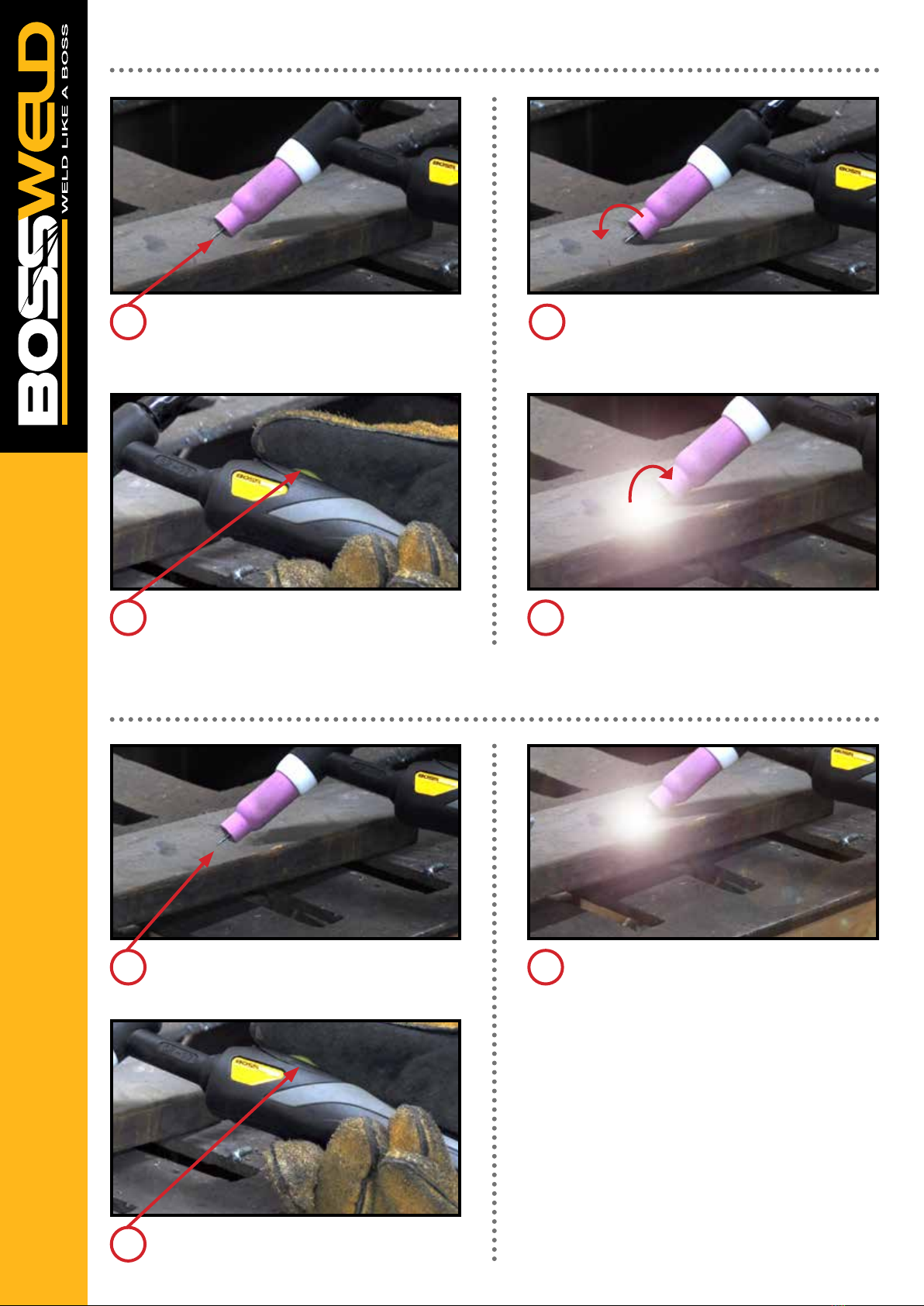
STRAIGHT GROUND
CORRECT PREPERATION - STABLE ARC INCORRECT PREPERATION - STABLE ARC
RADIAL GROUND
ARC WANDER
TUNGSTEN ELECTRODE
GAS LENS
STABLE ARC
FLAT TIP POINTED TIP
GRINDING WHEELGRINDING WHEEL
FILLER WIRE
Note: Do not use wheel for other jobs or tugsten can become contaminated and cause lower weld quality
Electrodes are often packed in sealed packaging to keep
moisture out. However, if a pack has been opened or
damaged, it is essential that the electrodes are redried
according to the manufacturer’s instructions.
ARC FORCE
Also called Dig and Arc Control. Gives a power source
variable additional amperage during low voltage
(short arc length) conditions while welding. Helps avoid
“sticking” stick electrodes when a short arc length is used.
POWER SOURCE
Electrodes can be operated with AC and DC power supplies.
Not all DC electrodes can be operated on AC power sources;
however AC electrodes may be used on either AC or DC