4
WARRANTY
This warranty is in addition to the statutory warranty provided under Australian Consumer Law, but does not
include damage resulting from transport, misuse, neglect or if the product has been tampered with.
The product must be maintained as per this manual, and installed and used according to these instructions on
an appropriate power supply. The product must be used in accordance with industry standards and acceptable
practice.
Special note:
If this welders duty cycle is exceeded the welder will enter “thermal overload” which will automatically
stop the welding output in order to protect, both the user and the welder. You will know the welder has
gone into thermal overload when the thermal overload light is illuminated. The welder will then cool
itself down, and once the thermal overload indicator light is no longer illuminated, welding can then
re-commence.
Please note. Exceeding the machine’s duty cycle, cannot be considered grounds for warranty or return.
This warranty covers the materials used to manufacture the machine and the workmanship used to produce the
item. This Warranty does not cover damage caused by:
1. Normal wear and tear due to usage
2. Misuse /abuse or Neglect of the item
3. Transport / handling breakages
4. Lack of maintenance, care and cleaning
5. Environmental factors, such as usage in temperatures exceeding 40 degrees, above 1000mt sea level, rain,
water, excessive damp, cold or humid conditions.
6. Improper setup or installation
7. Use on Incorrect voltage or non authorised electrical connections and plugs
8. Use of non standard parts
9. Repair, case opening, tampering with, modications to any part of the item by non authorised BOSSWELD
repairers.
This warranty covers the machine only and does not include Torches, Leads, Earth Clamps, Electrode holders,
Plasma Torches, Tig Torches and any of the parts on those items unless there is a manufacturing fault.
1. REGISTRATION
Purchasers are encouraged to register for warranty on our website. www.bossweld.com.au/warranty
2. TIME PERIOD - 2 Years
A warranty claim must be made within 2 years from the date of purchase of this product. Any claim must include
proof of purchase.
3. HOW TO MAKE A CLAIM - NEED SOME HELP?
• Visit our website www.bossweld.com.au/troubleshooting for many helpful tips and guides to assist with the
setup and usage of your new machine. Still stuck….?
• Call the BOSSWELD Helpdesk on 1300 899 710 for over the phone assistance.
• Visit www.bossweld.com.au,
• If the machine is not operational then return the item to the place of purchase.
BOSSWELD MAKES NO OTHER WARRANTY, EXPRESS OR IMPLIED. THIS WARRANTY IS EXCLUSIVE
AND IN LIEU OF ALL OTHERS, INCLUDING, BUT NOT LIMITED TO ANY WARRANTY OF
MERCHANTABILITY OR FITNESS FOR ANY PARTICULAR PURPOSE.
2
YEAR
LIMITED
WARRANTY
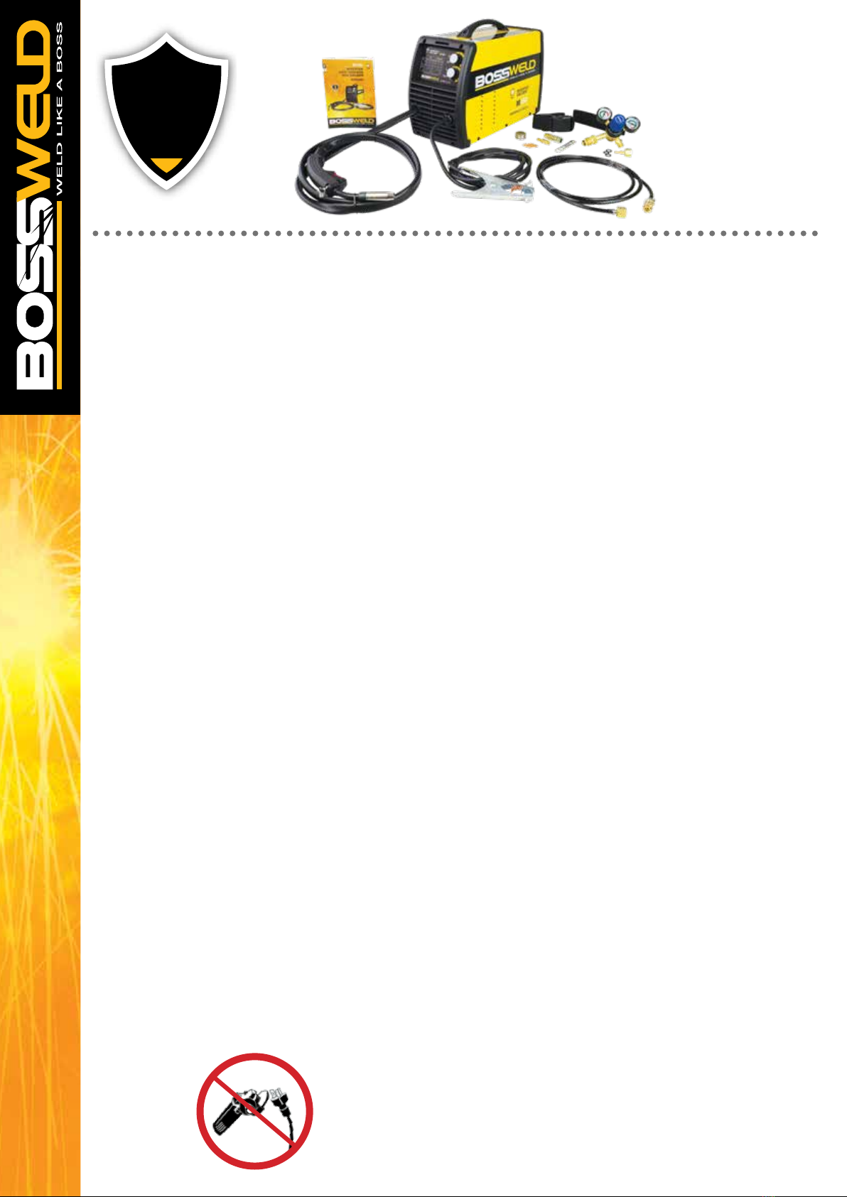
DO NOT GRIND YOUR PLUG
This will void any warranty on your machine