Boston gear ORC-S Series Installation instructions

Installation & Operation Instructions
Boston Gear®
ORC-S Series Trig-O-Matic
Overload Release Clutches
P-3003-BG
ORC-S Series

2Boston Gear • 800-825-6544 P-3003-BG
Contents
I. Introduction
A. Operating Principle .....................2
B. Resetting Instructions ...................3
C. Torque Adjustment .....................4
Il. Mounting Sprockets or Sheaves to Clutch
A. Type “T” Housing ....................5, 6
B. Type “B” Housing ....................5, 6
Ill. Locating and Mounting Clutch and
Couplings to Shaft
A. Location ............................7
B. Mounting Basic Clutch ..................7
C. Mounting Type “C” Flexible
Coupling.............................9
D. Mounting Type “N” Index and
Type “R” Rigid Couplings ................9
IV. Limit Switches .........................10
V. General Maintenance
A. Lubrication ..........................11
B. Annual Inspection .....................11
Vl. Repair Instructions
A. General Disassembly ..................11
B. Basic Unit Assembly...................12
C. Torque Verification ....................13
D. Limit Switch Actuating Plate
Assembly ...........................13
Exploded Parts View ...................16 - 18
Overload Release Clutches –
Standard Model S
Installation and Maintenance Instructions
I. Introduction
A. Operating Principle
The ORC Series, Model S Overload Release Clutch
consists of two basic components: the rotor and the
housing assembly. The clutch rotor is keyed and secured
to a shaft with a setscrew.
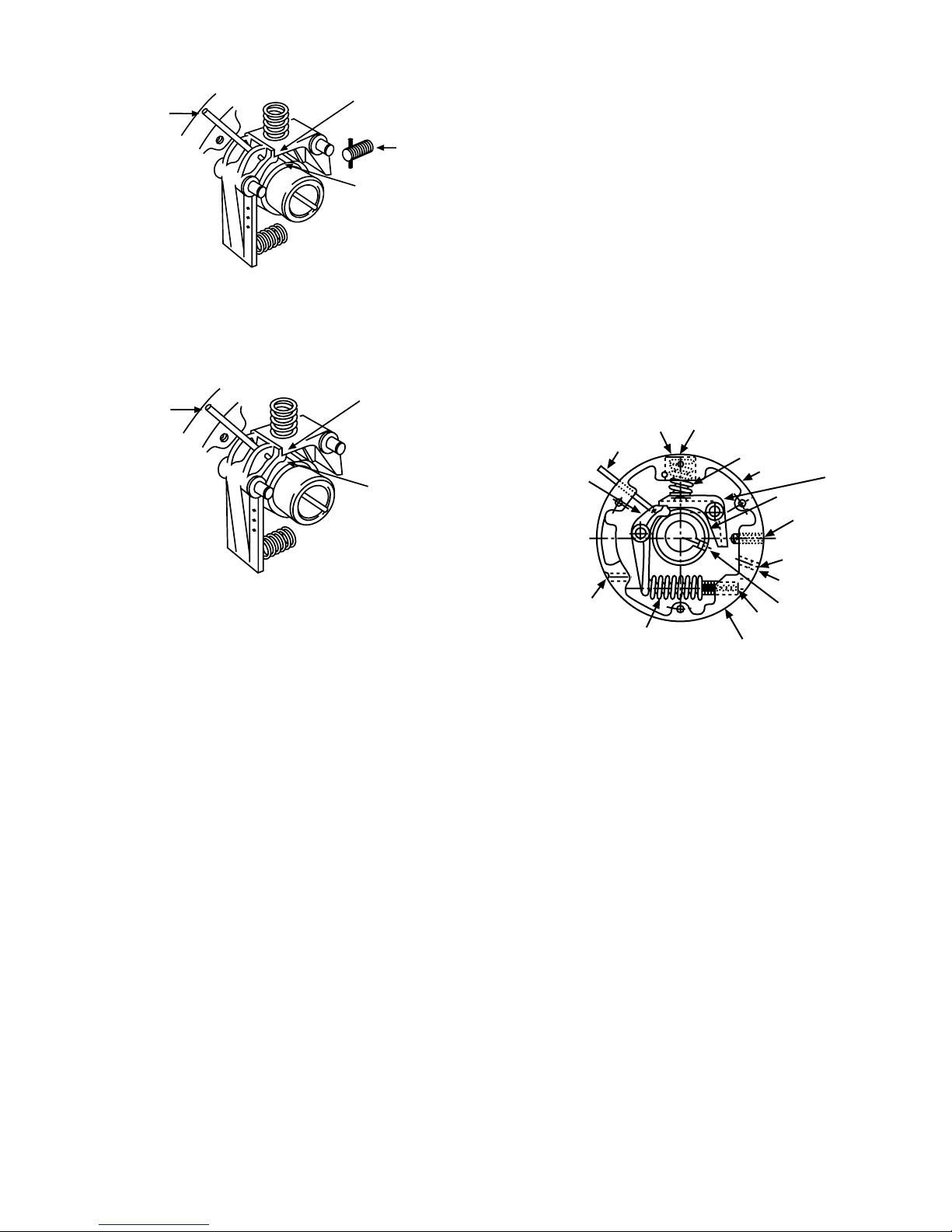
The housing assembly includes a drive pawl and a reset
pawl which are pivoted within the clutch housing. The
drive pawl is held engaged in the rotor notch by the
combined compression of the drive and reset springs as
shown in Figure 1. The combined compression of these
two springs determines the maximum torque which will
be transmitted without overload. With the clutch in the
engaged position shown in Figure 1, the rotor and the
housing are held together and the entire unit rotates with
the drive shaft at the same speed.
Figure 1
When an overload occurs, the rotor rotates from its
normal position within the housing. At this instant, the
combined compression of the drive and reset springs is
overcome. For a manual reset clutch, the drive pawl is
forced out of its engaged position from the rotor and as
it pivots up, the reset pawl lifts and locks the drive pawl
out of contact with the rotor as shown in Figure 2. The
clutch is then free to rotate until it is reset. For a clutch
with the automatic reset feature, the reset pawl applies
pressure to the top of the drive pawl, holding it in contact
with the rotor as shown in Figure 3.
Housing
Limit Switch Pin
Retracted
Reset Spring
Drive Pawl
Engaged With
Rotor
Rotor
Drive Spring
Boston Gear • 800-825-6544 P-3003-BG 3
Figure 2 - Manual Disengaged
Figure 3 - Automatic
B. Instructions
1. Manual Reset
Note: Be sure not to use a powered wrench as
it may cause damage to the reset pawl and/or
reset spring!
a. After the overload condition has been corrected,
rotate the drive until the rotor keyway is in
alignment with the hole stamped 22 located
on the outside diameter of the housing. (See
Figure4)
b. Reset the clutch by inserting a hex wrench into
the reset screw (Stamped 20) shown in Figure 4,
and turn the screw clockwise until the reset pawl
releases the drive pawl. Refer to Table 5 for the
proper wrench size.
c. After the drive pawl enters the rotor notch, turn
the wrench counterclockwise until the reset
screw has stopped at its original position, which
is approximately flush with the O.D. of the clutch
housing. This is essential to restore the
torque to its original setting.
d. Reducing the clutch torque setting may make
the reset procedure easier if the clutch is near
the maximum torque.
2. Automatic Reset
After one complete revolution the drive pawl will
automatically return to its original engaged position. After
the overload condition has been corrected, “jog” the
drive until the drive pawl engages with the rotor.
(Stamped 9)
Actuating
Pin
Drive Pawl
(Stamped 26)
Drive Spring
(Stamped 8)
Drive Spring Screw
Rotor Setscrew
Access Screw
(Stamped 22)
Reset Screw
(Stamped 20)
Rotor
Reset Pawl
Housing
Reset Spring
Reset Spring Screw
Limit Switch Pin
Extended
Reset Pawl Holds
Drive Pawl in Contact
With Rotor
Drive Pawl
Disengaged From
Rotor
Limit Switch Pin
Extended
Reset Pawl
Engages Notch
in Drive Pawl
Manual
Reset Scr
ew
Drive Pawl Locked
Out Of Contact
with Rotor
Figure 4 - Clutch Internal Components
(Stamped 20)

4Boston Gear • 800-825-6544 P-3003-BG
C. Torque Adjustment
The clutch is supplied with a torque selector dial. This
dial makes torque adjustments on the clutch possible.
There are mill marks on the housing near the hole
stamped 9 on the outside diameter of the housing.
The mill marks have stamped values indicating a
set, or minimum and maximum torque. (See Figure
5) If a drastic change in torque is desired, it may be
necessary to change springs. See Section Vl for spring
replacement.
Figure 5
1. Increasing the Torque.
a. Make sure the clutch is engaged.
b. Turn the torque adjustment screw clockwise
until it is flush with the milled depth of the
desired torque setting or until nuisance trips are
eliminated.
c. Check its operation.
2. Decreasing the Torque.
a. Make sure that the clutch is engaged.
b. Turn the torque adjustment screw
counterclockwise until it is flush with the milled
depth of the desired torque setting.
c. Check its operation.
3. See Figure 6 for Limit Switch Actuating
Mechanism adjustment.
Limit Switch Actuating Mechanism (LSAM)
In some cases, it may be necessary to adjust the
actuating mechanism. This is accomplished by first
setting the clutch at the minimum torque settings, and
second disengaging the clutch. Remove access plug
#5 (stamped #26) and insert an allen wrench into the
actuating adjusting screw #29. (Refer to Table 5 for
wrench sizes) Rotate adjusting screw #29 clockwise
until the spring pressure applied by the actuating spring
#28 against the actuating stud nut #39 is just sufficient
to release the actuating plate #31. The adjustment
should then be tested by resetting the clutch and
then disengaging it. If the adjustment is correct, the
actuating plate will release at the exact time of clutch
disengagement. Replace plug #5. If the trip plate does
not release, repeat the entire proess.
Figure 6
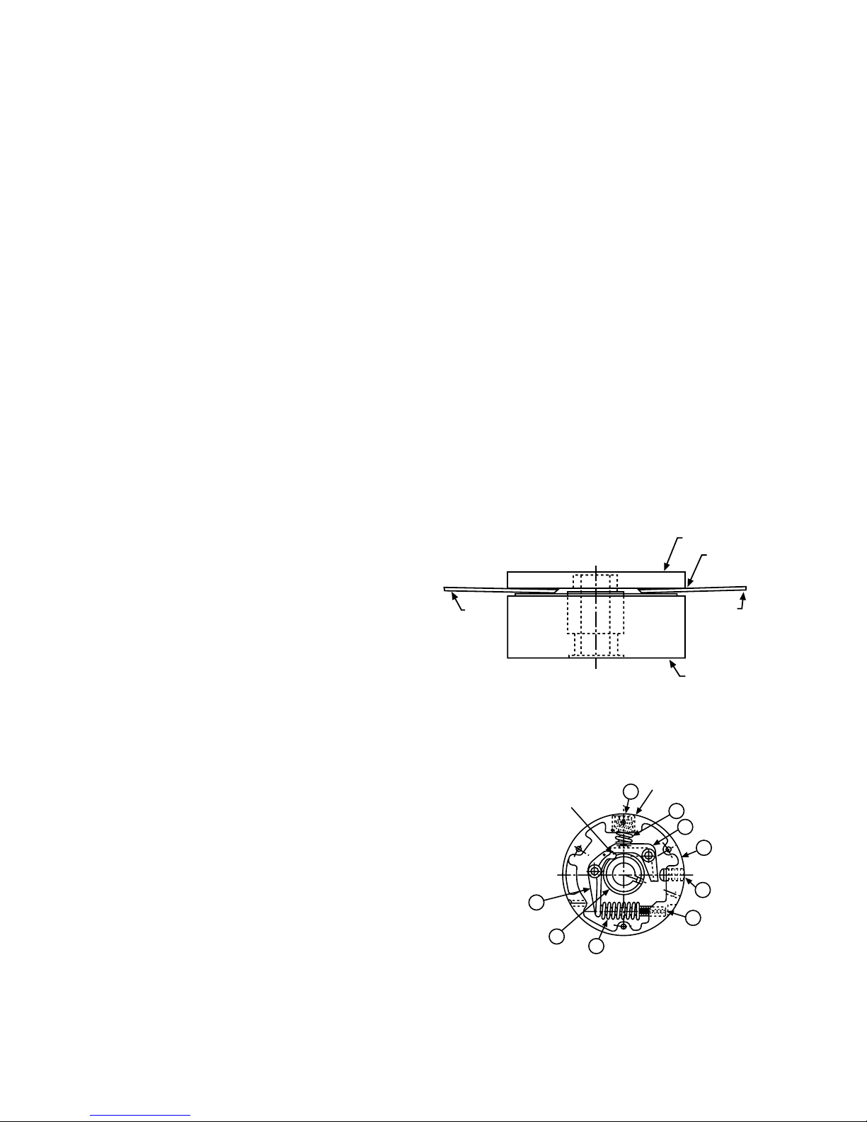
5Adjustment Access Plug
28 Actuating Spring
29 Actuating Adjusting Screw
30 Spring Mounting Screw
31 Actuating Plate
32 Trip Pin
35 Release Ring
38 Return Spring
39 Actuating Stud Nut
43 Spring Terminal
To
rque Adjusting Screw
Squar
e Wrench Socket
Milled Depth
For Max. Torque
Milled Depth For
Set or Min. Torque
Reset Spring
Disc
Lock Screw
Maximum Torque
Limit Stop Pin
43
32 35
31
38
30 39 28 29
5

Boston Gear • 800-825-6544 P-3003-BG 5
Table 1
Sprocket Mounting Screw Seating Torques
Size Screw
Size Qty Dowel
Size Qty Seating
Torque
Ream
Size
1 1/4-20 3 1/4 1 150 in.lb. .2495
2 5/16-18 3 5/16 1 305 in.lb. .3120
3 3/8-16 4 3/8 1 545 in.lb. .3745
4 1/2-13 4 1/2 1 1,300 in.lb. .4995
5 5/8-11 6 5/8 1 2,530 in.lb. .6245
6 5/8-11 6 5/8 1 2,530 in.lb. .6245
II. Mounting Sprockets or Sheaves to
Clutch
A. Type “T” Housing (Refer to Figure 7)
1. Inspect mating pilots on clutch and sprocket or
sheave for nicks or burrs and remove as required.
2. Position sprocket or sheave on housing and align
dowel pin holes.
3. Attach sprocket or sheave to housing with mounting
bolts and high collar lock washers. Refer to Table 1
for recommended seating torques.
4. Finish ream sprocket or sheave for dowel pin. Refer
to Table 1 for dowel pin and recommended ream
sizes.
5. Install dowel pins to a point where they bottom in
housing.
B. Type “B” Housing
A Type “B” is a basic unit and is sold without any
mounting hole arrangement. It is modified by the
customer for special applications. Refer to Figure 8.
Table 2
Minimum Number of Teeth of Standard Plate Sprockets Adaptable to Type “T” Clutch
Clutch
Size
Chain Size and Pitch
#25
1/4 in.
Pitch
#35
3/8 in.
Pitch
#40
1/2 in.
Pitch
#41
1/2 in.
Pitch
#50
5/8 in.
Pitch
#60
3/4 in.
Pitch
#80
1 in.
Pitch
#100
1-1/4 in.
Pitch
#120
1-1/2 in.
Pitch
#140
1-3/4 in.
Pitch
#180
2 in.
Pitch
1 40 28 22 22 18 — —————
2 54 36 28 28 22 19 — — — — —
3 X 45 34 36 28 25 19 — — — —
4 X X 42 45 36 30 23 19 — — —
5 X X X X 42 36 30 22 19 17 —
6 — — X X X 48 36 30 24 21 19
Notes:
1. X - On Application Only.
2. For smaller sprockets consult factory. As in most cases, a design modification can be made.
6Boston Gear • 800-825-6544 P-3003-BG
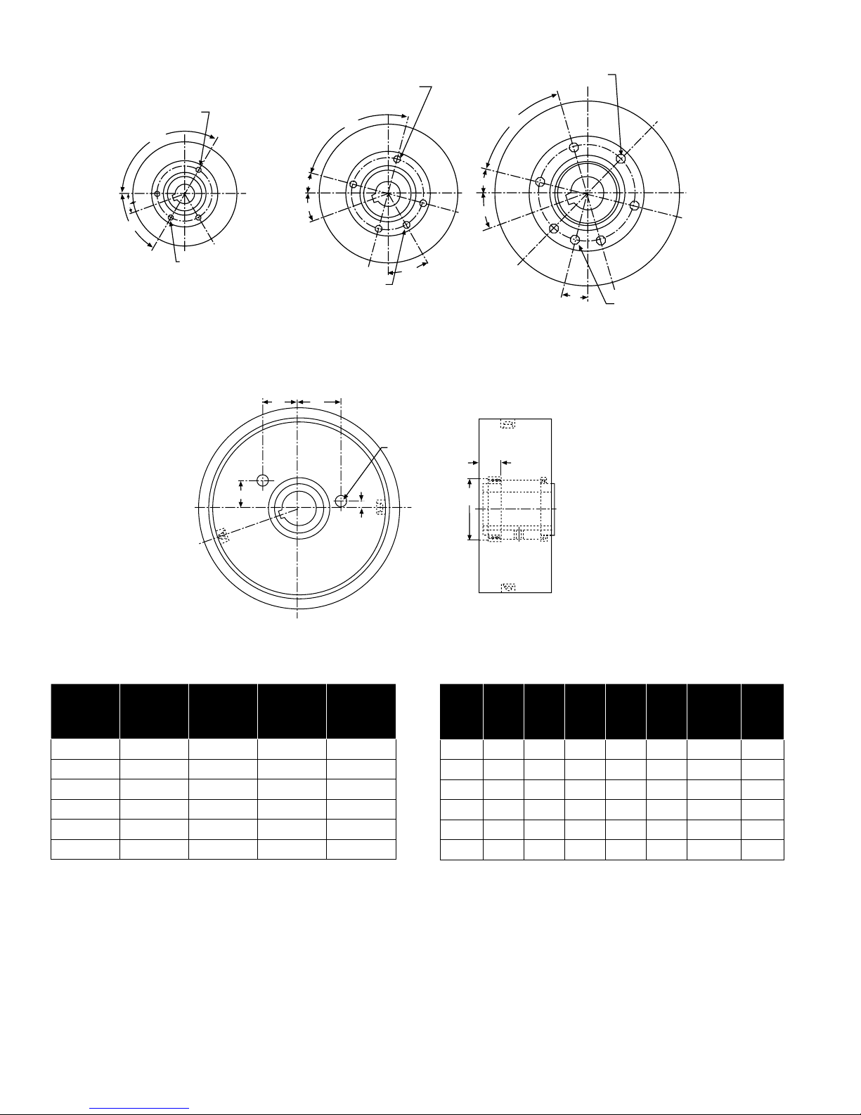
Table 3 - Type “T” Mounting Hole Patterns
Size Thread Depth Bolt Circle
Pilot Dia.
+.000
-.002
1 1/4-20 .50 2.375 1.875
2 5/16-18 .50 3.000 2.250
3 3/8-16 .62 4.125 3.250
4 1/2-13 .87 5.000 3.203
5 5/8-11 1.00 6.250 4.125
6 5/8-11 1.00 8.750 6.000
Notes:
1. Mounting bolts must be minimum 160,000 PSI tensile, Rc 36-43.
2. Dowel pins must be minimum 150,000 PSI shear, Rc 50-58 core
hardness.
Table 4 - Type “B” Housing Dimensions
Size A B C D E
F
+.000
-.002
G
1 .81 .81 1.06 .11 .31 1.500 .69
2 .90 1.25 1.37 .18 .37 1.875 .81
3 1.25 1.62 1.94 .29 .50 2.750 .94
4 1.56 2.12 2.37 .43 .56 2.828 1.48
5 1.94 2.62 3.00 .58 .69 4.000 1.62
6 2.62 3.50 3.87 .90 .87 5.500 2.00
Notes:
1. The “E” Dimension on Table shows pawl trunnion holes. These holes
are not through holes and they should be avoided when mounting a
coupling, sprocket, etc. to the clutch.
3 Tapped Holes at 120°
120° Typ.
20°
60°
1 Dowel Hole at 60°
Sizes 1 and 2 Mountin
g
Hole Pattern
4 Tapped Holes at 90°
90° Typ.
15°
20°
30°
1 Dowel Hole at 30°
6 Tapped Holes at 60°
60° Typ.
14°
20°
14°
1 Dowel Hole at 14°
Sizes 5 and 6 Mountin
g
Hole PatternSizes 3 and 4 Mountin
g
Hole Pattern
"B" "C"
"A"
"D"
"E" Dia. Typ.
"G"
"F"
Dia.
Figure 7 - Type “T” Standard Mounting Hole Patterns
Figure 8 - Type “B” Housing Conguration

Boston Gear • 800-825-6544 P-3003-BG 7
III. Locating and Mounting Clutch and
Couplings to Shaft
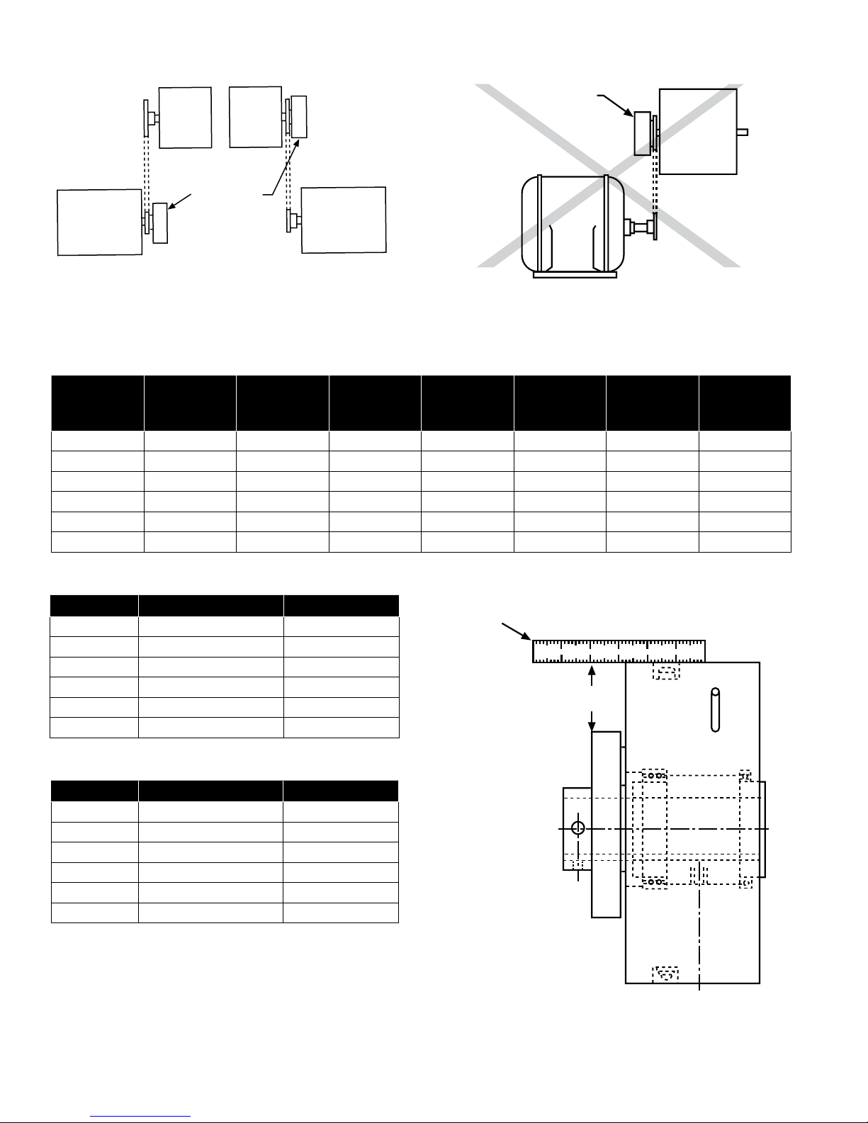
A. Location
The clutch should always be located as close as
possible to the source of an overload condition. Figures
9 through 12 indicate both preferred and not preferred
locations for mounting an ORC Series, Model S Overload
Release Clutch.
Note: Clutch mounted sprockets, etc. and couplings
should be positioned as close to a supporting
bearing as possible to minimize overhung loads.
A minimum shaft engagement of 1-1/2 times the
shaft diameter is recommended for clutch and
coupling flange installation.
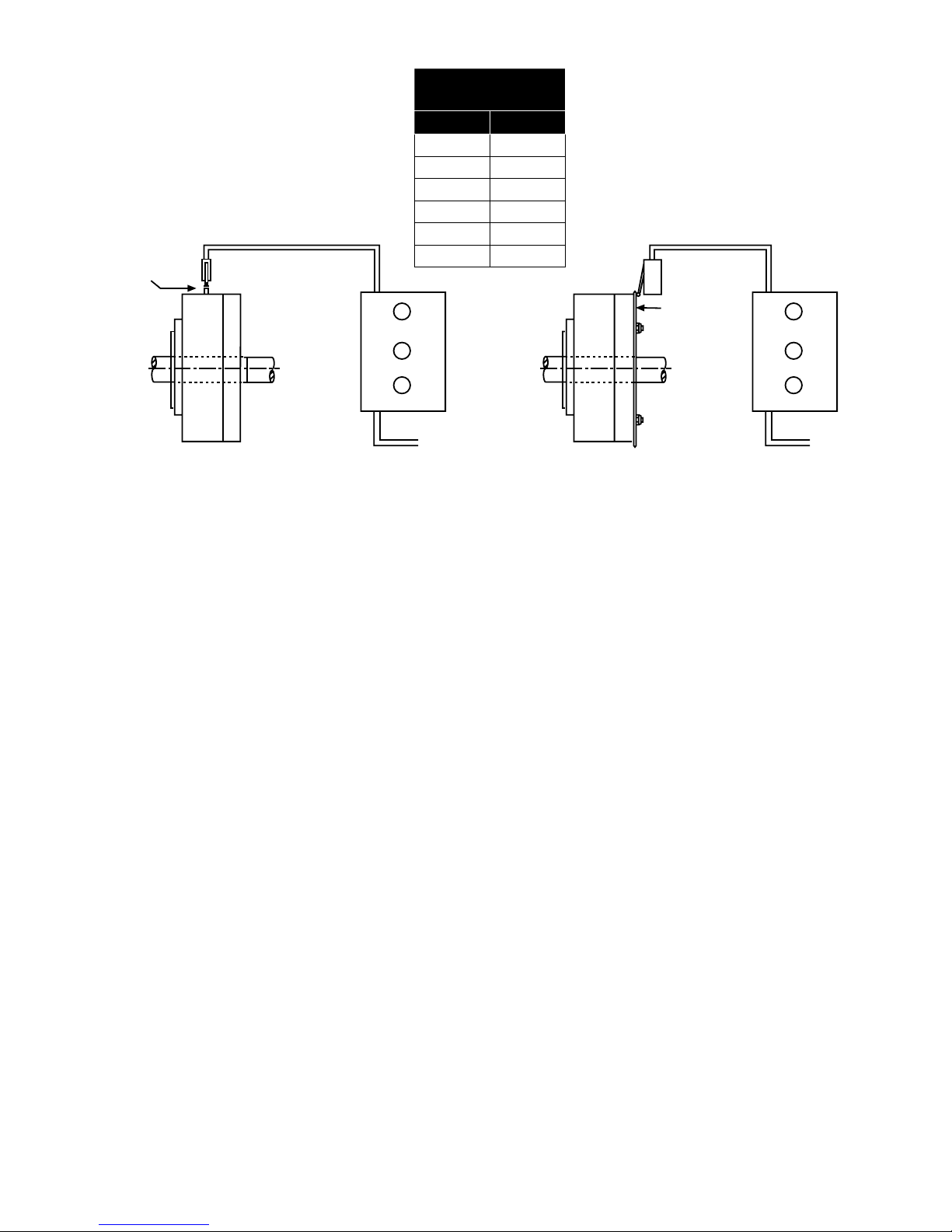
1. Direct Drives
a. Figure 9 shows the preferred location for
mounting in a direct drive application. The
clutch is mounted on the low speed side of the
reducer, and transmits power from its housing,
through its rotor to the driven shaft.
b. Locating the clutch as shown in Figure 10 is
not preferred. Here the clutch is mounted on
the high-speed side of the reducer. Generally,
mounting in this manner requires the clutch to
be hypersensitive to perform satisfactorily.
2. Indirect Drives
a. Either location of the clutch shown in Figure 11
is preferred in indirect drive applications.
b. The mounting location in Figure 12 is not
preferred for the same reasons as those for
Figure 10. Always consult the factory when a
mounting of this type is necessary.
B. Mounting Basic Clutch
1. Inspect shaft and key for any nicks or burrs and
remove any that may be present.
2. Remove the access screw from the hole stamped
22 outside of the clutch housing. Make sure that the
clutch is engaged where the rotor keyway is in line
with the hole stamped 22.
3. Position shaft key and slide clutch onto shaft.
4. Align sprocket or sheave mounted to clutch with
mating sprocket or sheave in drive train. Refer to
installation and alignment instructions furnished with
sprocket or sheave.
5. Select the correct hex wrench from Table 5 and
insert it through the hole stamped 22 in the housing.
Tighten the rotor setscrew securing the clutch to the
shaft.
Note: Turn wrench clockwise only! Do not remove
setscrew from rotor!
Refer to Table 6 for recommended setscrew
seating torques.
6. Remove the hex wrench and replace access screw
in the housing.
Flexible Coupling Coupling
Half
Overload Clutch
Motor Reducer Machine
Coupling Half Overload Clutch Flexible Coupling
Motor Reducer Machine
Figure 9
Figure 10
8Boston Gear • 800-825-6544 P-3003-BG
Table 5 - Wrench Size Chart
Clutch Size
Drive Spring
Screw Hex
Wrench
Reset Spring
Screw Square
Wrench
Manual Reset
Screw Hex
Wrench
Rotor
Setscrew Hex
Wrench
Access
Screws Hex
Wrench
Locking
Screw Hex
Wrench
Adjustment
Screw Hex
Wrench
1 3/16 3/8 3/16 3/32 1/8 3/32 1/16
2 1/4 3/8 1/4 1/8 5/32 3/32 5/64
3 5/16 1/2 5/16 3/16 3/16 1/8 1/8
4 5/16 1/2 3/8 1/4 5/16 1/8 1/8
5 3/8 1/2 1/2 5/16 5/16 1/8 1/8
6 3/4 3/4 1/2 5/16 5/16 1/8 1/8
Table 6 - Rotor Setscrew Seating Torques
Size Screw Size Seating Torque
1 10-32 36 in. lb.
2 1/4-28 87 in. lb.
3 3/8-24 290 in. lb.
4 1/2-20 620 in. lb.
5 5/8-18 1,325 in.lb.
6 5/8-18 1,325 in.lb.
Table 7 - Coupling Setscrew Seating Torques
Size Screw Size Seating Torque
1 5/16-18 165 in. lb.
2 3/8-16 290 in. lb.
3 3/8-16 290 in. lb.
4 1/2-13 620 in. lb.
5 1/2-13 620 in.lb.
6 1/2-13 620 in.lb.
Driving
Member
Driven Machinery
Overload Clutch
Location
Driving
Member
Overload Clutch
Motor
Reducer
Straightedge
Coupling Parallel Alignment
Offset
12 345
Figure 12
Figure 13
Figure 11

Boston Gear • 800-825-6544 P-3003-BG 9
C. Mounting Type “C” Flexible Coupling
1. After the clutch has been mounted on its shaft as
explained in Section lll, inspect the coupling shaft
and key for any nicks or burrs and remove any that
are present.
2. Make sure that the coupling shaft keyway is in
alignment with the clutch shaft keyway. Position
shaft key and slide coupling onto the appropriate
shaft.
3. Slide the coupling flange onto the coupling studs.
The coupling flange and adapter should be
separated by a gap of 1/8”.
4. Secure the coupling to drive shaft by tightening the
two setscrews located in the hub of the flange. Refer
to Table 7 for recommended coupling setscrew
seating torques.
5. Parallel Alignment
a. Place a straightedge across the clutch housing
and coupling flange as shown in Figure 13.
b. Measure the offset around the periphery of these
two components without rotating the shafts.
c. If the difference in offset from any two points
180 degrees apart exceeds the maximum value
shown in Table 8, the shafts must be realigned.
Table 8 - Type “C” Misalignment
Size Maximum Allowable Misalignment
Parallel Angular
1 .012” .074”
2 .015” .091”
3 .016” .102”
4 .027” .159”
5 .031” .183”
6 .045” .231”
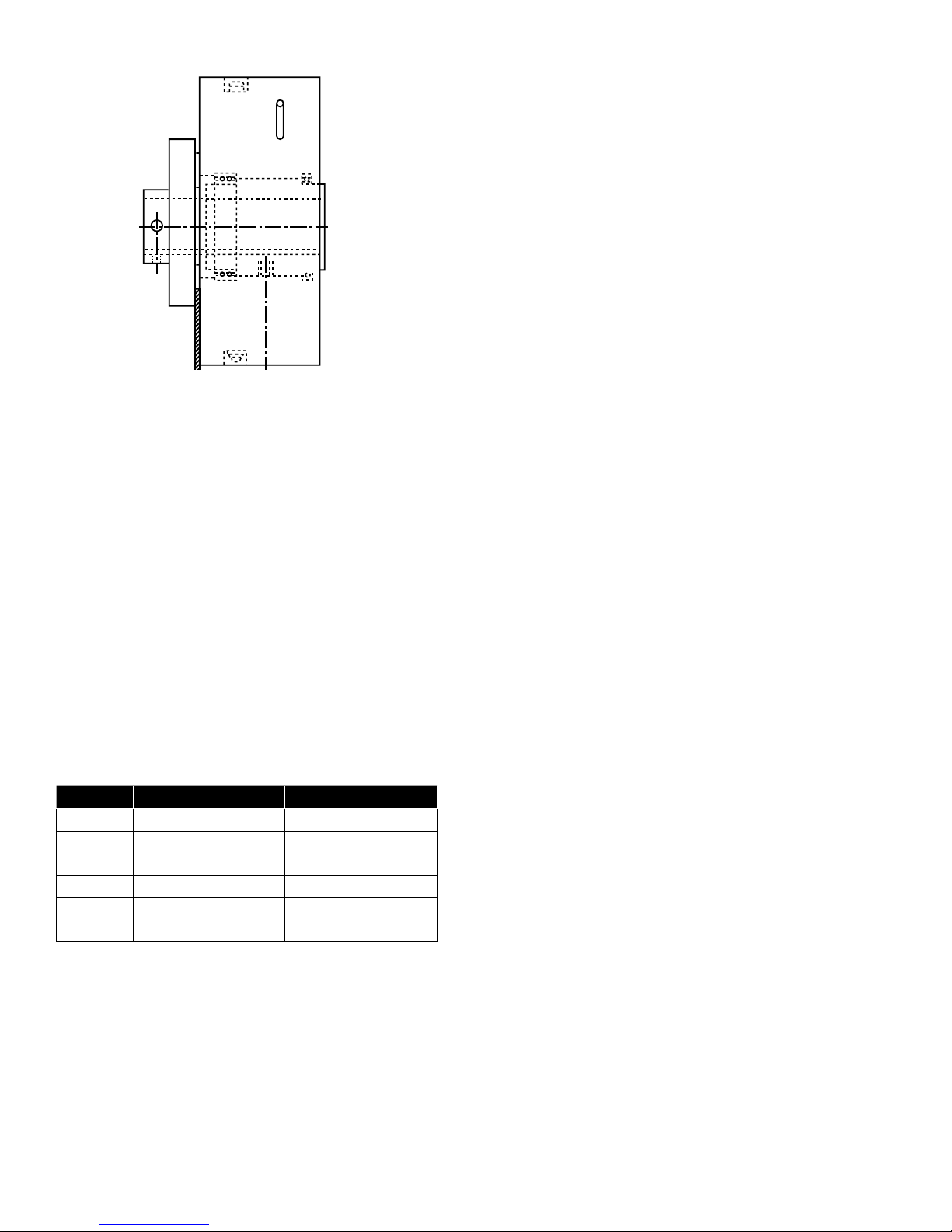
6. Angular Alignment
a. Measure the gap around the periphery between
the coupling flange and the clutch housing
without rotating the shafts. (See Figure 14).
b. If the difference between any two points 180
degrees apart exceeds the maximum angular
misalignment shown in Table 8, the shafts must
be realigned.
c. If a correction is required to satisfy angular
alignment requirements, then recheck the
parallel alignment.
D. Mounting the “N” Index Coupling and Type
“R” Rigid Coupling
1. After the clutch has been mounted on its shaft
as explained in Section lll, inspect mating pilots
of clutch and coupling for any nicks or burrs and
remove any that are present.
2. Inspect coupling shaft and key for any nicks or burrs
and remove any that are present.
3. In the case of a Type “R” make sure that the
coupling shaft keyway is in alignment with the clutch
shaft keyway. Position the shaft key and slide the
coupling flange onto the shaft.
4. Slide the coupling onto the clutch housing making
sure that the coupling pilot fits into the housing pilot
and that the mounting holes are aligned. In the case
of a Type “N” index coupling, make sure that the
desired mounting slots are aligned with the clutch
housing mounting holes.
5. Secure the coupling to the drive shaft by tightening
the two setscrews located in the hub of the flange.
Refer to Table 7 for recommended setscrew seating
torques.
6. Parallel Alignment
a. Place a straightedge across the clutch housing
and coupling flange as shown in Figure 13.
b. Measure the offset around the periphery of these
two components without rotating the shafts.
c. The shafts must be aligned until no offset exists
or is equal at all points around the periphery.
10 Boston Gear • 800-825-6544 P-3003-BG
Figure 14
7. Angular Alignment
a. Measure the gap around the periphery between
the coupling flange and clutch housing without
rotating the shafts. (See Figure 14)
b. The shafts must be aligned until no gap exists or
is equal at all points around the periphery.
c. If a correction is required to satisfy angular
alignment requirements, then recheck the
parallel alignment.
Note: The Type “N” and “R” coupling connection
is rigid and does not allow for forgiveness of
parallel or angular misalignment. To eliminate
unnecessary bearing loads, both shafts must be
in near perfect alignment.
Table 9 - Coupling Mounting Bolt Seating Torques
Size Bolt Size Seating Torque
1 5/16-18 160 in.lb.
2 3/8-16 280 in.lb.
3 1/2-13 700 in.lb.
4 5/8-11 1,200 in.lb.
5 5/8-11 1,200 in.lb.
6 5/8-11 1,200 in.lb.
8. Loosen the coupling setscrews and attach coupling
to clutch with hex head bolts and flat washers. Refer
to Table 9 for recommended bolt seating torques.
Secure coupling to drive shaft by tightening the
setscrews to the recommended seating torques in
Table 7.
IV. Limit Switches
The ORC Series, Model S Overload Release Clutch
is available with two types of limit switch actuators,
a limit switch pin (LSAP) and a limit switch actuating
mechanism (LSAM).
A. Limit Switch Pin
A Limit Switch Pin is furnished as a standard item to
activate a limit switch that triggers the electrical controls.
The Limit Switch Pin protrudes radially from the clutch
housing and its travel is controlled by the drive pawl
motion upon disengagement. The Limit Switch Pin can
be used if the housing continues to rotate when an
overload occurs and the rotor stops, i.e, the housing
is the driver and the rotor is the driven. Housing RPM
has to be considered to determine the time for the Limit
Switch Pin to revolve around before contacting the limit
switch, see Figure 15, for Limit Switch Pin Travel.
The standard Limit Switch Pin extension is 1 inch from
the outside diameter of the clutch housing. It can also
be made flush with the surface of the housing in an
engaged position.
B. Limit Switch Actuating Mechanism
A Limit Switch Actuating Mechanism provides instant
operation of a limit switch to immediately shut down the
drive or actuate an alarm should an overload occur.
The mechanism is entirely contained in the clutch cover
and is actuated by the motion of the drive pawl. When
an overload occurs, the drive pawl motion releases the
actuating plate and it trips a limit switch. The total travel
of the plate is 5/16 of an inch. (See Figure 15)
The actuating plate must be reset by manually pushing
it back into position. The clutch must be engaged when
resetting the plate or the plate will not reset when the
clutch is disengaged.
Feeler Gage
Boston Gear • 800-825-6544 P-3003-BG 11
A limit switch should be able to operate within the plate
travel of 5/16 of an inch. The switch should be wired in
parallel with a jog circuit so that the drive can then be
indexed to the start/run circuit.
V. General Maintenance
A. Lubrication
The Overload Release Clutch is prelubricated at the
factory and is also equipped with a grease pack fitting.
For optimum performance and wear resistance it is
suggested that the clutch be lubricated with a Bentone
type, NLGI grade 0 grease. The lubrication schedule
should be in accordance with good operating practices
for the equipment on which the clutch is mounted. The
clutch is also supplied with a grease relief fitting. When
there is enough grease in the clutch any excess grease
will be extruded through the relief fitting.
B. Annual Inspection
The Overload Release Clutch is constructed of heavy
duty materials. Under reasonably clean conditions
the unit will operate with a minimum of maintenance.
A scheduled annual inspection of bearings, pawls,
rotor, springs, tripping mechanism, and other internal
components is suggested. However, the actual
frequency should be in accordance with good operating
practices for the equipment on which the clutch is
installed.
VI. Repair Instructions
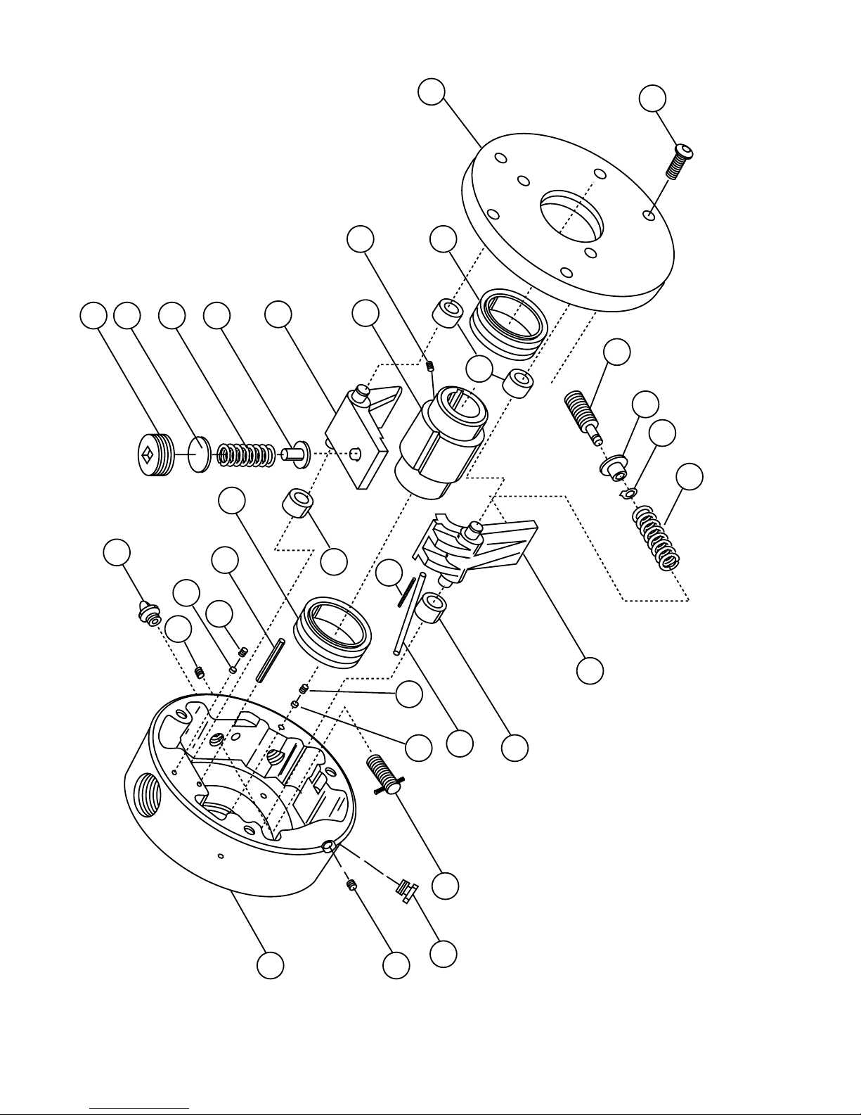
A. General Disassembly
1. All item numbers in parenthesis will refer to the key
numbers shown in the clutch exploded view drawing
and parts identification tables.
2. Place the clutch preferably in a three-jaw chuck with
the actuating plate or cover facing up.
3. There are two locking screws (25) located on the
face of the cover which lock down the reset spring
screw (14) and the drive spring screw (21). Loosen
these screws to relieve the pressure on the drive
spring screw and reset spring screw.
4. Turn the reset spring screw (14) counterclockwise to
relieve the compression on the reset spring (19).
5. Remove the sealing wax from the drive spring screw
(21) and turn the screw counterclockwise to relieve
the compression on the drive spring (18).
6. Remove the cover screws (27).
7. Pry off the cover (8). Use care not to break the inner
pilot of the cover. (See Figure 16)
8. Remove the reset screw (14) and take out the reset
spring (19), and the ball thrust (20) through the hole
stamped 9.
Limit Switch Pin
Standard
Limit
Switch
Pin
Limit
Switch
Start
Jog
Stop
To Motor
ORC
Overload
Clutch
Limit Switch Actuating Mechanism
Limit
Switch
Optional
Limit
Switch
Actuating
Mechanism
ORC
Overload
Clutch
Start
Jog
Stop
To Motor
Limit Switch Pin
Travel
Size Travel
1 .13 “
2 .13”
3 .13”
4 .13”
5 .13”
6 .25”
Figure 15 - Limit Switch Layout
12 Boston Gear • 800-825-6544 P-3003-BG
9. Remove the reset pawl (11 ) by simply lifting out.
10. Remove the drive pawl (10) and the drive spring (18).
This will require a little more effort because of the
slight pressure on the drive spring.
11. Remove the housing (1) from the mounting surface
and press out the rotor (12).
12. If clutch is manual reset, remove the reset screw (24)
by turning clockwise into the housing.
13. Inspect hardened bushings (3) in housing (1) and
cover (8) for excessive wear.
14. Replace any worn or broken parts.
B. Basic Unit Assembly
1. If clutch is manual reset, install the reset screw
(24) from the inside of the housing turning counter-
clockwise until the reset screw pin stops the screw
from turning.
2. Press the long end of rotor (12) into housing bearing
(2).
3. This step is for manual reset only. Go to next step
for automatic reset. Install the drive pawl (10) into
the appropriate hole in the housing (1), and the reset
pawl (11) into its appropriate hole in the housing.
Check the fit of the reset pawl into the notch of the
drive pawl with the clutch disengaged. The reset
pawl should fit approximately one-third of the way
into the notch. Grinding the nose of the reset pawl
may be necessary to obtain the proper fit. (See
Figure 17)
4. Remove the drive pawl (10). The drive pawl and
the drive spring (18) will have to be installed
simultaneously. If a drastic change in torque is
desired, use this step to change the drive spring.
Place one end of the drive spring over the drive
spring thrust washer (22). Insert the knob of the drive
pawl into the other end of the drive spring. Insert the
trunnion of the drive pawl into the hardened bushing
in the housing, while the nose of the drive pawl fits
into the notch of the rotor (12).
5. Coat the inside of the housing and all components
with a quality all-purpose grease. A Bentone type,
NLGI grade 0 grease or equivalent is recommended.
6. Insert the reset spring disc (15) inside the reset
spring screw (14). Apply grease to the surface of the
disc.
7. If a drastic change in torque is desired, use this step
to change the reset spring. Place the reset spring
(19) on the surface of the reset spring disc. Apply
grease to the end of the ball thrust (20) and insert
ball thrust into the reset spring.
8. Apply grease to the threads of the reset spring screw
(14) and insert the assembly of the reset spring
screw, reset spring disc (15), reset spring (19), and
ball thrust (20) through the hole stamped 9 on the
housing. Tighten the reset spring screw until it is
flush with the surface of the housing. (See Figure 17)
9. Fill the entire housing cavity with grease to ensure a
proper grease packing.
10. Press the cover on to the housing assembly. Make
sure that the trunnion holes and the cover screw
holes line up.
11. Install the cover screws and tighten to the
recommended seating torques in Table 10.
Cover
Pry Bar
Excessive Force
May Break Inner
Pilot of Cover
Pry Bar
Housing
Reset Pawl About 1/3
into Notch of Drive Pawl
Reset Screw Flush With
Surface of Housing
14
15
11
1
24
21
10
12
18
Figure 17
Figure 16

Boston Gear • 800-825-6544 P-3003-BG 13
C. Torque Verication
1. Place the clutch in a chuck or vise with the cover
facing upward.
2. Insert the appropriate size arbor and key into rotor.
(See Figure 18)
3. Turn the drive spring screw (21) clockwise until it is
flush with the surface of the housing.
4. The clutch is supplied with a torque selector dial.
The torque selector dial is the mill marks located at
the hole stamped 9 on the housing. If a drive spring
(18), reset spring (19), and/or a reset spring screw
(14) were replaced, chances are that the stamped
torque values on the dial are no longer valid. It may
be necessary to grind the old numbers off and to
stamp new ones.
5. Tighten the reset spring screw (14) until it reaches
the limit stop pin (4). This will be the maximum
torque position. If the maximum torque is not
desired, tighten the reset spring screw to one of the
locations on the torque selector dial.
6. Disengage the clutch with a torque wrench. Fine
tune the torque by turning the drive spring screw
(21) until the desired release torque is obtained.
7. Refer to Section I, C for further details on torque
adjustment.
8. Once the desired release torque is obtained, tighten
the locking screws (25) located over the drive spring
and reset spring screws to ensure that they will not
move. The unit is now ready for installation. Refer to
Section lll for installation of basic clutch.
Table 10 - Cover Screw Seating Torques
Clutch
Size Screw Size Quantity Seating
Torque
1 1/4-20 3 100 in.lb.
2 5/16-18 3 200 in.lb.
3 3/8-16 3 350 in.lb.
4 1/2-13 4 850 in.lb.
5 5/8-11 4 1,700 in.lb.
6 5/8-11 4 1,700 in.lb.
Figure 18
D. Limit Switch Actuating Mechanism (LSAM)
Assembly
1. Apply a graphite lubricant to the release ring groove
of the cover (8).
2. Insert the actuating stud (40) through the appropriate
hole in the release ring (35). To identify this hole
place the release ring in the groove of the cover.
When the trip pin holes line up with the through
holes of the cover, the actuating stud hole will line
up with the counterbored hole in the groove of the
cover.
3. Install the actuating stud nut (39) onto the actuating
stud (40) and tighten.
4. Install a spring terminal (43) on each end of the
return spring (38). Clutch sizes 5 & 6 require two
return springs.
5. Insert a spring terminal screw (41) through the hole
of the spring terminal (43), and place a spacer collar
(36) on the end of the screw. Insert the end of the
screw into the threaded hole of the release ring (35)
and tighten. The end of the screw may protrude past
the release ring. Grind the end of the screw flush
with the surface of the release ring. Install second
spring terminal screw on clutch sizes 5 & 6 as just
described. Move to Step 13 for clutch sizes 5 & 6.
6. Press the trip pins (32) into the trip plate (31).
7. Install a bowed snap ring (34) into the groove of
each trip pin located next to the trip plate.
8. Place the trip plate flat on a table with counterbored
holes facing up. Insert the thrust springs (37) into the
counterbores.
Torque Wrench
Arbor
Trig-O-Matic Clutch
Vice or Chuck Jaws

14 Boston Gear • 800-825-6544 P-3003-BG
9. Place the cover (8) over the trip plate, lining up the
counterbores in the cover with the springs.
10. Place the release ring (35) into the groove of the
cover. Make sure that all of the holes line up properly.
11. Insert a spring terminal screw (41) through the hole
of the other spring terminal (43) and place a spacer
collar (36) on the end of the screw. Insert the end
of the screw into the tapped hole of the cover and
tighten.
12. Push down on the cover and release ring until the
release ring engages into the grooves of the trip
pins. Install two snap rings (33) into the grooves of
each trip pin. Move to Step 22.
13. Place the release ring (35) into the groove of the
cover. Make sure that all of the holes are properly
aligned.
14. Insert the trip pins (32) through the matching holes
in the release ring (35) and cover (8). Make sure that
the tapped hole of the trip pin is inserted first.
15. Slide the release ring (35) counterclockwise so that
the ring engages into the grooves of the trip pins.
16. Insert a spring terminal screw (41) through the other
spring terminal (43) and place a spacer collar (36)
on the end of the screw. Insert the screw into the
tapped hole in the cover and tighten. Repeat this
process for the other return spring .
17. Turn the cover over so that the release ring is facing
down against the surface of the table.
18. Insert the thrust springs (37) into the counterbores of
the cover.
19. Place the trip plate (31) over the cover making sure
that the springs will sit in the counterbores of the trip
plate and that all the holes properly line up.
20. Press down on the trip plate (31) until it stops
against the trip pins.
21. While pressing down on the trip plate (31) insert the
plate mounting screws (42) into the tapped holes of
the trip pins and tighten.
22. Press the cover assembly onto the housing
assembly (1). Make sure that the trunnion holes and
the mounting screw holes line up.
23. Install the cover screws (27) and tighten to the
recommended seating torques shown in Table 10.

Boston Gear • 800-825-6544 P-3003-BG 15
NOTES
3
1
5
724
26 25
16
3
10
17
3
2
4
25
26
5
6
14
15
19
20
11
12 13
98
27
18
23
22
21
16 Boston Gear • 800-825-6544 P-3003-BG
ORC Series, Model S with Limit Switch Pin (LSAP) Types SA & SM
Boston Gear • 800-825-6544 P-3003-BG 17
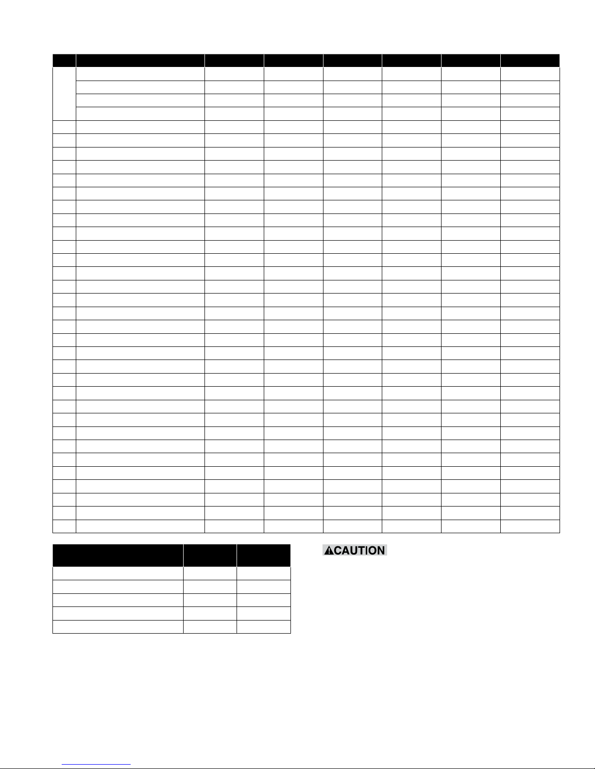
Part Identication - Model S with Limit Switch Pin (LSAP) Types SA & SM
Key No. Name Size 1 (Qty.) Size 2 (Qty.) Size 3 (Qty.) Size 4 (Qty.) Size 5 (Qty.) Size 6 (Qty.)
*1
T Housing Ass’y., or 711257-XXX (1) 711148-XXX (1) 711180-XXX (1) 711223-XXX (1) 711238-XXX (1) 711266-XXX (1)
B Housing Ass’y.,or 711258-XXX (1) 711149-XXX (1) 711181-XXX (1) 711224-XXX (1) 711239-XXX (1) 711267-XXX (1)
C Housing Ass’y.,or 711259-XXX (1) 711150-XXX (1) 711182-XXX (1) 711225-XXX (1) 711240-XXX(1) 711268-XXX (1)
N/R Housing Ass’y, 711260-XXX (1) 711151-XXX (1) 711183-XXX (1) 711226-XXX (1) O/A O/A
2 Housing Bearing 039273-041 (1) 039273-043 (1) 039273-044 (2) 039273-038 (1) 711900-006 (1) 711900-008 (1)
3 Hardened Bushing — 730634-002 (2) 730634-003 (2) 730634-004 (2) 730634-005 (2) —
4 Limit Stop Pin 730422-001 (1) 730422-001 (1) 730422-002 (1) 730422-002 (1) 730422-003 (1) 730422-003 (1)
5 Access Screws 040940-031 (2) 040940-042 (2) 074102-003 (2) 074102-078 (2) 074102-078 (2) 040940-078 (2)
6 Grease Fitting 034186-029 (1) 034186-029 (1) 034186-029 (1) 034186-029 (1) 034186-029 (1) 034186-029 (1)
7 Relief Fitting 034186-028 (1) 034186-028 (1) 034186-028 (1) 034186-028 (1) 034186-028 (1) 034186-028 (1)
8 Cover Ass’y 711261-001 (1) 711146-001 (1) 711185-001 (1) 711219-001 (1) 711242-001 (1) 711269-001 (1)
9 Cover Bearing 039273-040 (1) 039273-042 (1) 039273-045 (1) 039273-038 (1) 711900-005 (1) 711900-007 (1)
3 Hardened Bushing — 730634-002 (2) 730634-003 (2) 730634-004 (2) 730634-005 (2) —
10 Drive Pawl 730429-001 (1) 730430-001 (1) 730431-001 (1) 730432-001 (1) 730433-001 (1) 730434-001 (1)
*11 Reset Pawl 730367-XXX (1) 730368-XXX (1) 730369-XXX (1) 730370-XXX (1) 730371-XXX (1) 730372-XXX(1)
**12 Rotor Assembly 710354-001 (1) 710354-002 (1) 710354-003 (1) 710354-004 (1) 710354-005 (1) 710354-006 (1)
13 Rotor Setscrew 043243-012 (1) 043243-022 (1) 043243-041 (1) ** (1) 043243-058 (1) 043243-058 (1)
14 Reset Spring Screw 730382-001 (1) 730382-002 (1) 730382-003 (1) 730382-004 (1) 730382-005 (1) 730382-006 (1)
15 Reset Spring Disc 730383-001 (1) 730383-002 (1) 730383-003 (1) 730383-004 (1) 730383-005 (1) 730383-006 (1)
16 LSAP Assembly 710355-001 (1) 710355-002 (1) 710355-003 (1) 710355-004 (1) 710355-005 (1) 710355-006 (1)
17 Roll Pin 040942-044 (1) 040942-044 (1) 040942-045 (1) 040942-045 (1) 040942-046 (1) 040942-045 (1)
18 Drive Spring - Low Torque Range (L) 730385-001 (1) 730385-007 (1) 730385-014 (1) 730385-020 (1) 730385-026 (1) 730385-032 (1)
19 Reset Spring - Low Torque Range (L) 730385-005 (1) 730385-011 (1) 730385-018 (1) 730385-024 (1) 730385-030 (1) 730385-035 (1)
18 Drive Spring - Medium Torque Range (M) 730385-001 (1) 730385-007 (1) 730385-015 (1) 730385-020 (1) 730385-026 (1) 730385-032 (1)
19 Reset Spring - Medium Torque Range (M) 730385-006 (1) 730385-012 (1) 730385-019 (1) 730385-025 (1) 730385-031 (1) 730385-036 (1)
18 Drive Spring - High Torque Range (H) 730385-001 (1) 730385-009 (1) 730385-015 (1) 730385-021 (1) 730385-027 (1) 730385-033 (1)
19 Reset Spring - High Torque Range (H) 730385-006 (1) 730385-013 (1) 730385-019 (1) 730385-025 (1) 730385-031 (1) 730385-037 (1)
20 Ball Thrust — 730386-001 (1) 730386-002 (1) 730386-003 (1) 730387-001 (2) 730387-002 (2)
21 Drive Spring Screw 730379-001 (1) 730379-002 (1) 730379-003 (1) 730379-003 (1) 730380-001 (1) 730381-001 (1)
22 Drive Spring Washer 730388-001 (1) 730388-002 (1) 730388-003 (1) 730388-003 (1) 730388-004 (1) 730388-005 (1)
23 Snap Ring — 040682-029 (1) 040682-030 (1) 040682-030 (1) 040682-030 (1) 040682-031 (1)
24 Reset Screw Ass’y. 710356-001 (1) 710356-002 (1) 710356-003 (1) 710356-004 (1) 710356-005 (1) 710356-006 (1)
25 Locking Screw 074102-015 (2) 074102-015 (2) 074102-031 (2) 074102-031 (2) 074102-027 (2) 074102-027 (2)
26 Locking Insert 730389-001 (2) 730389-001 (2) 730389-002 (2) 730389-002 (2) 730389-003 (2) 730389-003 (2)
27 Cover Screw 041315-048 (3) 041315-062 (3) 041315-077 (3) 041315-106 (4) 041315-121 (4) 041315-021 (4)
* Dash Numbers Are:
SA/SB/SC
Automatic
SM/SP/SS
Manual
T Housing Ass’y. -001 -002
B Housing Ass’y. -001 -002
C Housing Ass’y. -001 -002
N/R Housing Ass’y. -001 -002
Reset Pawl -001 -003
**Dependent upon bore—consult the factory.
Note: Please include clutch catalog number when ordering any spare
parts.
Rotating equipment is potentially
dangerous and could cause injury or damage if not
properly protected. Follow all applicable codes and
regulations.
In accordance with our established policy
to constantly improve our products, the
specications contained herein are subject
to change without notice.

18 Boston Gear • 800-825-6544 P-3003-BG
ORC Series, Model S with Limit Switch Actuation Mechanism (LSAM) Types SB, SC, SP & SS

Boston Gear • 800-825-6544 P-3003-BG 19
Part Identication - Model S with Limit Switch Actuating Mechanism (LSAM)
Types SB, SC, SP & SS
Key No. Name Size 1 (Qty.) Size 2 (Qty.) Size 3 (Qty.) Size 4 (Qty.) Size 5 (Qty.) Size 6 (Qty.)
8 Cover Ass’y. (LSAM) 711262-001 (1) 711187-001 (1) 711108-001 (1) 710766-001 (1) 711190-001 (1) 711270-001 (1)
9 Cover Bearing 039273-040 (1) 039273-042 (1) 039273-045 (1) 039273-038 (1) 711900-005 (1) 711900-007 (1)
3 Hardened Bushing — 730634-002 (2) 730634-003 (2) 730634-004 (2) 730634-005 (2) —
10 Drive Pawl (LSAM) 710290-001 (1) 710291-001 (1) 710292-001 (1) 710293-001 (1) 710294-001 (1) 710295-001 (1)
28 Actuating Spring 730414-001 (1) 730415-001 (1) 730416-001 (1) 730417-001 (1) 730418-001 (1) 730419-001 (1)
29 Adjustment Screw 018006-004 (1) 018006-017 (1) 018006-047 (1) 018006-047 (1) 018006-047 (1) 018006-047 (1)
30 Mount. Rivet/Screw 730420-001 (2) 730420-001 (2) 730420-002 (2) 730420-002 (2) 730420-002 (2) 074110-018 (2)
Plate Ass’y (SB/SP), 710204-001 (1) 710205-001 (1) 710206-001 (1) 710207-001 (1) — —
Plate Ass’y (SC/SS) 710204-002 (1) 710205-002 (1) 710206-002 (1) 710207-002 (1) — —
31 Plate (SB/SP), or 730397-001 (1) 730398-001 (1) 730399-001 (1) 730400-001 (1) 730401-001 (1) 730402-001 (1)
Plate (SC/SS) 730397-002 (1) 730398-002 (1) 730399-002 (1) 730400-002 (1) 730401-002 (1) 730402-002 (1)
32 Trip Pin 730403-001 (3) 730404-001 (3) 730405-001 (3) 730406-001 (4) 730407-001 (4) 730408-001 (4)
33 Snap Ring 040682-035 (6) 040682-035 (6) 040682-036 (6) 040682-030 (8) — —
34 Bowed Snap Ring 040682-032 (3) 040682-032 (3) 040682-033 (3) 040682-034 (4) — —
35 Release Ring 730391-001 (1) 730392-001 (1) 730393-001 (1) 730394-001 (1) 730395-001 (1) 730396-001 (1)
36 Spacer Collar 730409-001 (2) 730409-002 (2) 730409-002 (2) 730409-002 (2) 730409-002 (4) 730409-002 (4)
37 Thrust Spring 730410-001 (3) 730410-002 (3) 730410-002 (3) 730410-002 (4) 730410-002 (4) 730410-003 (4)
38 Return Spring 730411-002 (1) 730411-001 (1) 730411-002 (1) 730411-001 (1) 730411-002 (2) 730411-001 (2)
39 Actuating Stud Nut 730412-001 (1) 730412-002 (1) 730412-003 (1) 730412-004 (1) 730412-004 (1) 730412-004 (1)
40 Actuating Stud 074111-126 (1) 074111-126 (1) 730413-001 (1) 730413-002 (1) 730413-002 (1) 730413-002 (1)
41 Terminal Screw 074110-003 (2) 074110-017 (2) 074110-017 (2) 074110-017 (2) 074110-017 (4) 074110-017 (4)
42 Plate Mount. Screw — — — — 730561-001 (4) 730561-002 (4)
43 Spring Terminal 730421-001 (2) 730421-002 (2) 730421-002 (2) 730421-002 (2) 730421-002 (4) 730421-002(4)
C Coupling Ass’y. 710296-001 (1) 710297-001 (1) 710298-001 (1) 710299-001 (1) O/A O/A
Coupling Bushing 730275-001 (3) 730275-002 (3) 730275-003 (4) 730275-004 (4) — —
Setscrew 040940 041 (2) 040940-003 (2) 040940-003 (2) 040940-067 (2) — —
Coupling Pin 730278-001 (3) 730278-002 (3) 730278-003 (4) 730278-004 (4) — —
N/R Coupling Ass’y. 710301-001 (1) 710302-001 (1) 710303-001 (1) 710334-001 (1) O/A O/A
Mounting Screw 074118-062 (3) 074118-077 (3) 074118-093 (4) 074118-110 (4) — —
Flat Washer 074117-004 (3) 074117-006 (3) 074117-009 (4) 074117-013 (4) — —
Setscrew 040940-041 (2) 040940-003 (2) 040940-003 (2) 040940-067 (2) — —
Note: Please include clutch catalog number when ordering any spare parts.
ORC Model S Series Part Numbering System
C3 SA L9 P16 800
Type
T– Sprocket Mount
C– Flexible Coupling
N– Indexing Coupling
R– Rigid Coupling
Torque Range
L– Light
M– Medium
H– Heavy
(Specify
Torque Setting)
L9 – Light
M9 – Medium
H9 – Heavy
Model
SA – Standard Model, Fully
Automatic Reset with Pin
Actuator
SB – Standard Model, Semi-
Automatic Reset with
Plate Actuator
SC – Standard Model, Semi-
Automatic Reset with
reduced diameter Plate
Actuator
SM – Standard Model, Manual
Reset with Pin Actuator
SP – Standard Model, Manual
Reset with Plate Actuator
SS – Standard Model, Manual
Reset with reduced
diameter Plate Actuator
P20ORC 50A28
Series
Overload
Release
Clutch
Unit Bore
P– Bored to Size (in 1/16")
M– Metric Bored to Size
(mm)
Example: P 20 = 1-1/4 bore
Coupling Bore
(Type C, N, or R Only)
Blank–Non-Coupled Units
P– Bored to Size (in 1/16")
M– Metric Bored to Size (mm)
Example: P 20 = 1-1/4 bore
-B1SBK
Clutch Material/Paint
(Cast Iron)
Blank–Standard Paint
BK – White BostKleen Paint
SBK – Stainless BostKleen
Paint
Size
1
2
3
4
5
6
Sprocket Options
Blank–No Sprocket
Included
50A28
50 – Chain Size
A– Sprocket Type
28 – Number of Teeth
See catalog for
available options
Torque Setting
Set point within the torque range
Blank–Standard torque range with clutch
set at the minimum value
Special Options
T# – Special Feautures Contact Boston Gear Engineering
B1 – Ball Bearings for High Speed
Applications (sizes 1-4 only)
L1 – Pressure Lubed Bearings (Sizes 3-6 Only)
S1 – Static Balance
Z1 – Pin Removed on “SA” and “SM” Models Only

www.bostongear.com
701 Carrier Drive
Charlotte, NC 28216
704-588-5610
Warranty
Boston Gear warrants that products manufactured or sold by it shall be free from defects in material and
workmanship. Any products which shall within two (2) years of delivery, be proved to the Company’s satisfaction
to have been defective at the time of delivery in these respects will be replaced or repaired by the Company at its
option. Freight is the responsibility of the customer. The Company’s liability under this limited warranty is limited
to such replacement or repair and it shall not be held liable in any form of action for direct or consequential
damages to property or person. THE FOREGOING LIMITED WARRANTY IS EXPRESSLY MADE IN LIEU OF
ALL OTHER WARRANTIES WHATSOEVER, EXPRESS, IMPLIED AND STATUTORY AND INCLUDING WITHOUT
LIMITATION THE IMPLIED WARRANTIES OF MERCHANTABILITY AND FITNESS.
No employee, agent, distributor, or other person is authorized to give additional warranties on behalf of Boston
Gear, nor to assume for Boston Gear any other liability in connection with any of its products, except an officer of
Boston Gear by a signed writing.
P-3003-BG 9/18
Table of contents
Other Boston gear Microphone System manuals


