Phonic PCT-3000 User manual

User's Manual
Manual del Usuario
PCT-3000
PCT-3000SYS

Dual Channel Diversity Wideband Wireless System
Sistema Inalámbrico Diverso de Banda Ancha y de
Doble Canal
English Español
ENGLISH........................................I
ESPAÑOL.......................................II
APPENDIX.....................................III
V1.0 07/28/2015
PCT-3000
PCT-3000SYS

English
3PCT-3000
Introduction.........................................................................................1
Features.....................................................................................1
Operation.....................................................................................1
Front Panel..............................................................................2
Setup Diagram...................................................................................3
Rear Panel.....................................................................................3
WM-X Wireless Transmitter......................................................................4
Group Settings.................................................................................5
Channel Settings...........................................................................5
User-Defined Frequency Settings......................................................5
Synchronize With Transmitter.................................................................5
Squelch Settings.......................................................................................5
Lock Mode..............................................................................................5
Troubleshooting........................................................................................6
Rack Mounting Kit.....................................................................................6
Specifications.....................................................................................7
APPENDIX
Dimensions.......................................................................................1
CONTENTS
USER'S MANUAL
Phonic preserves the right to improve or alter any information within this
document without prior notice

4
English
PCT-3000
1. Read these instructions before operating this
apparatus.
2. Keep these instructions for future reference.
3. Heed all warnings to ensure safe operation.
4. Follow all instructions provided in this document.
5. Do not use this apparatus near water or in locations
where condensation may occur.
6. Clean only with dry cloth. Do not use aerosol or liquid
cleaners. Unplug this apparatus before cleaning.
7. Do not block any of the ventilation openings. Install
in accordance with the manufacturer
í
s instructions.
8. Do not install near any heat sources such as radiators,
heat registers, stoves, or other apparatus (including
.
9. Do not defeat the safety purpose of the polarized or
grounding-type plug. A polarized plug has two blades
with one wider than the other. A grounding type plug
has two blades and a third grounding prong. The wide
blade or the third prong is provided for your safety. If
the provided plug does not into your outlet, consult
an electrician for replacement of the obsolete outlet.
10. Protect the power cord from being walked on or
pinched particularly at plug, convenience receptacles,
and the point where they exit from the apparatus.
11. Only use attachments/accessories by the
manufacturer.
12. Use only with a cart, stand, tripod, bracket, or
table by the manufacturer, or sold with
the apparatus. When a cart is used, use caution
when moving the cart/apparatus
combination to avoid injury from tip-
over.
13. Unplug this apparatus during lighting
storms or when unused for long
periods of time.
14. Refer all servicing to service personnel.
Servicing is required when the apparatus has been
damaged in any way, such as power-supply cord or
plug is damaged, liquid has been spilled or objects
have fallen into the apparatus, the apparatus has
been exposed to rain or moisture, does not operate
normally, or has been dropped.
IMPORTANT SAFETY INSTRUCTIONS
CAUTION: TO REDUCE THE RISK OF ELECTRIC SHOCK,
DO NOT REMOVE COVER (OR BACK)
NO USER SERVICEABLE PARTS INSIDE
REFER SERVICING TO QUALIFIED PERSONNEL
The lightning flash with arrowhead symbol, within an
equilateral triangle, is intended to alert the user to the
presence of uninsulated
ì
dangerous voltage
î
within the
product
í
magnitude to constitute a risk of electric shock to persons.
The exclamation point within an equilateral triangle is in-
tended to alert the user to the presence of important operat-
ing and maintenance (servicing) instructions in the literature
accompanying the appliance.
WARNING: To reduce the risk of or electric shock, do
not expose this apparatus to rain or moisture.
CAUTION: Use of controls or adjustments or performance
of procedures other than those may result in
hazardous radiation exposure.
The apparatus shall not be exposed to dripping or splashing and that no objects with liquids, such as vases,
shall be placed on the apparatus. The MAINS plug is used as the disconnect device, the disconnect device shall
remain readily operable.
Warning: the user shall not place this apparatus in the area during the operation so that the mains switch
can be easily accessible.
CAUTION
RISK OF ELECTRIC SHOCK
DO NOT OPEN

English
1PCT-3000
Introduction
Congratulations on your purchase of the all new Phonic
PCT-3000 dual channel wideband wireless receiver or the
complete PCT-3000SYS wireless microphone system. The
culmination of years of working in the wireless domain, the
PCT-3000 combines the tried and true wireless technology
that Phonic is famous for with a brand new stand-alone
construct. The PCT-3000 systems were built to deliver
superb RF reliability and transparent audio performance
in a wide variety of professional applications, even under
the harshest conditions. Ideal for live stage performances,
speeches, karaoke and more, the PCT-3000 wireless
systems ensure you never have to worry about microphone
cables again.
Features
• Run up to 48 microphones interference-free in a single
venue, maximum 10 channels per group at a time
• 29presetchannelgroupsplus1user-denedgroup,
Groups 1 to 8 offer 10 Channels per group while Groups
9 to 29 offer 16 channels (432 frequencies in total)
• Clear display offers frequency information for ultimate
control over transmission
• Rapid auto-scan syncing with transmitters for easy,
immediate operation
• Balanced and unbalanced output through XLR and ¼”
TRS phone jacks
• Advanced diversity circuitry helps to improve stability
and avoid dropouts
• Broad channel range makes multiple systems ideal for
use at any one time
• Rear-panel -10, 0, +6 dB switch for contouring level to
input devices
• Stable performance even in the event that multiple units
or channels are used
• Flexible noise squelch technology for clear, noise-free
performances every time
• Detachable diversity antennas for exible setup and
installation
• Transmitters feature LCD screens with battery and
frequency monitoring/control
• Perfect for Karaoke (KTV) bars and live stage
performances
PCT-3000SYS
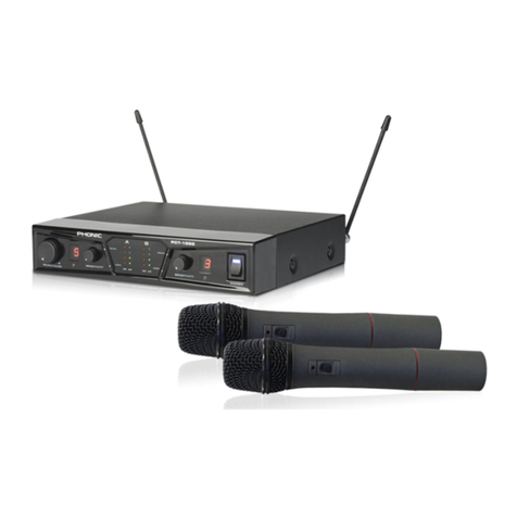
• PCT-3000SYS includes a single PCT-3000 receiver in
addition to two WM-X handheld microphone transmitters
Sold Separately
• WL-X Wireless Lavalier Microphone with Bodypack
Transmitter
• WH-X Wireless Headset Microphone with Bodypack
Transmitter
Operation
Auto Scan
1. PoweronthePCT-3000wirelessreceiverbyickingthe
power switch found on the rear of the device.
2. Power on your WM-X handheld microphone by pushing
and holding the power button.
3. Hold the WM-X transmitter close to the PCT-3000
receiver with the IR port on each facing each other
(within 30cm).
4. Push and hold the PCT-3000's MENU button for 3
seconds to enter the conguration mode. Push the
MENU button repeatedly until the lock is blinking. Push
and hold the channel's UP button to initiate autoscan.
5. Upon a successful connection, the RF meter on the
PCT-3000willllupandtheAFmeterwilllightupas
you speak into the microphone.
Manual Group Setting
1. Power-on PCT-3000 receiver and the microphone
transmitter.
2. Push and hold the menu button on the PCT-3000
receiver for 3 seconds. Pushing the menu button again
will scroll through the PCT-3000's on screen functions.
3. When the Group section is highlighted, push the up and
down buttons to adjust the value. Push menu again to
move to the Channel option and change the selected
channel.
4. Whenthelocksymbolisashing,pushandholdthe
DOWN button to initiate the transfer to the WM-X
receiver.
5. Push and hold the menu button to save your settings
andexitcongurationmode.
6. Alternatively, on the WM-X transmitter, push and hold
the UP button to enter edit mode. You can then push
the up and down buttons to adjust the "GROUP"
used. Push and hold the UP button again to adjust the
"FREQUENCY". These must match the GROUP and
FREQUENCY numbers set in the receiver.
<30cm

2
English
PCT-3000
Front Panel
1. LCD Screen
This screen displays all properties relevant to the operation
of the PCT-3000. This includes group information, frequency
information, squelch details, and even transmitter battery
details. For more information on the LCD screen, please
refer to page 3.
2. IR Port
This is used to communicate group and frequency
information to the transmitter unit. When establishing a
connection between the receiver and transmitter, the IR
ports on both units should be facing one another so as to
ensure clean communication.
3. Menu Button
Push this button to access the PCT-3000’s on screen
functions. Simply pushing the button will toggle the mute
status of the channel on and off.
Push and hold the menu button for three seconds to access
thePCT-3000’scongurationmode.Wheninconguration
mode, pushing the menu button will allow you to scroll
through the different parameters available within the
software (as shown below).
Push and hold the Menu button to save your settings and
exitcongurationmode.
4. Up / Down Buttons
These buttons are used in conjunction with the PCT-3000’s
menu to allow control of the internal software.
Rear Panel
5. BNC Antenna Connector
The PCT-3000 comes complete with 2 antennas. Connect
themtotheseBNCconnectors.Screwintoplacetoxthem
securely to the receiver unit. The antenna currently used
by each of the PCT-3000’s channels is displayed at the
top of the LCD screen.
6. Output Connectors
Each of the PCT-3000 output
channels features balanced
XLR and ¼” TRS connectors.
These are ideal for connection
to mixing consoles or other
input devices. XLR connector
wiring can be found to the right.
7. Mode Switch
This switch has two options: mixed and separated. When
set to mixed, microphones A and B will be combined and
sent out both outputs A and B. When the switch is set to
separated, the microphone signals will be sent to their
corresponding outputs.
8. Operating Level Switch
This switch lets the user determine the output level of
the A and B outputs. When set to -6, the unit is ideal for
consumer-level application. The 0 and +10 settings are
ideal for professional devices.
9. DC Power Input
Connect the included DC power adapter to this input.
Connect the power plug end into an appropriate AC power
source.
10. Power Switch
Use this power switch to turn the receiver unit on and off.
5 9 10 6 7 8
12
3 4
System Overview
LOCK SQUELCHCHANNELGROUP
USER/PRESET
FREQUENCY
GND
HOT (+)
COLD (-)

English
3PCT-3000
13 14 15 16 17
1819202111
12
LCD Screen
11. RF Meter
When a connection is established between the transmitter
and receiver, this meter will light up. A full meter means
there is a strong connection between the microphone and
receiver, while a low meter means the microphone may be
too far away or there may be interference present.
12. Lock
When this icon is lit the PCT-3000 is in lock mode. This
ensures no accidental changes are made to the system.
PushtheUPorDOWNbuttonstoactivate.Whenashing,
pressing and holding the UP button will initiate autoscan.
13. AF Meter
This meter will light up when a signal is received from the
transmitter. Essentially when you talk into the connected
microphone, the AF meter will display the incoming signal.
14. Mute Indicator
This indicator will light up when the channel is muted.
A quick push of the MENU button will mute/unmute the
channel.
15. Squelch Level
The squelch level indicates the sensitivity level of the
channel. Decreasing the squelch will increase the
transmission range, but with higher susceptibility to noise.
Increasing the squelch will decrease the transmission
range.
16. Frequency
The transmission frequency is listed here in MHz.
17. Battery Meter
This indicates the battery level of the transmitter synced
with the receiver. Phonic recommends using fresh batteries
in your microphone for each new performance.
18. Channel
Indicates the currently selected channel within the selected
frequency group. Groups 1 to 8 each have 10 channels
whereas 9 to 29 each have 16 channels.
19. Group
Indicates the currently selected frequency group. There
are 29 independent groups in preset mode and 1 group
in user mode.
20. User / Preset
This indicates whether the currently selected frequency
isauser-denedvalueorafactorypreset.Thereare29
independent groups in preset mode and 1 group in user
mode.
21. Channel A/B
This indicates the antenna currently used by the channel.
Setup Diagram
The included antenna should be inserted into the antenna
ports on the rear of the device. The BNC end should be
inserted into the port and screwed into place.
The DC port is for the included DC power supply.
When connecting the receiver’s output to the line-level
inputofamixeroramplier,switchtheOperatingLevel
Switch to the 0 position. Low sensitivity may occur if switch
to the -10 position.
When connecting the receiver’s output to the microphone
input of a mixer, the Operating Level Switch should be set
to the -6 position. The incoming signal may be excessive
if set to the 0 or +10 positions.
Phonic suggests use of high quality audio cables when
making connections. The PCT-3000 features balanced
outputs that support both balanced and unbalanced
connections.

4
English
PCT-3000
WM-X Wireless Transmitter
22. Top Grille
This removable grille with internal foam prevents wind and
POP noises from being sent through the microphone. Twist
counter-clockwise to unscrew the grille.
23. Color-Coded Ring
Phonic provides different colored rings to differentiate
microphones.
24. Power On/Off Button
Push and hold the power button for a short time to turn the
WM-X microphone on and off.
25. LCD Screen
This small LCD screen displays group, channel, frequency
and battery status information.
26. Control Buttons
Press these buttons to adjust parameters on the WM-X
transmitter. Pressing the ▲ or ▼ buttons will allow the
screen to display frequency information. Push and hold the
▲buttontoentercongurationmodeandadjustGROUP
and CHANNEL settings.
27. IR Port
This Infrared (IR) port receives signals from PCT-3000
receiver to synchronize group, channel and/or frequency
information. Hold the microphone’s IR port towards the IR
part on the receiver unit to allow them to communicate.
28. Housing
The lower part of the handheld microphone’s housing
includes both the transmitter circuit and the battery holder. It
can simply be twisted counter-clockwise to remove to allow
access to the battery compartment. Phonic recommends
two AA alkaline batteries. Ensure the polarity orientation is
correct when installing batteries (as shown below).
WARNING: Remove batteries from the transmitter unit in
the event that it will go unused for more than a couple of
weeks. This is to avoid leakage, corrosion, or other possible
issues that may arise.
22
23
24
25
26
27
28
Group / Channel
The currently selected channel and group are displayed
as standard within the WM-X’s display. Push and hold the
▲buttontoinitiatechannelsetting.Pushandhold▼to
initiategroupsettingmode.Oncethisisdone,the▲or▼
buttons can be used to adjust the group/channel settings.
Frequency information
Whilenottypicallydisplayed,pushingthe▲or▼buttons
on the WM-X microphone will display the exact frequency
used by the transmitter (in MHz).
Battery Indicator
This meter will indicate how the WM-X transmitter’s battery
is faring. Phonic suggests inserting fresh batteries before
every use.

English
5PCT-3000
Group Settings
1. Push and hold the MENU button on the receiver.
2. Push the MENU button until the GRP option is blinking.
3. When GP is blinking, use the UP and DOWN buttons
to adjust the selected group. The PCT-3000 has 26
preset and 1 user-adjustable groups available for use.
4. Push and hold the MENU button to save your settings.
Channel Settings
1. Push and hold the MENU button on the receiver.
2. Push the MENU button until the CH option is blinking.
3. When CH is blinking, use the UP or DOWN buttons on
the PCT-3000 receiver to adjust the selected channel.
4. The PCT-3000 has 16 selectable channels per group
onbothpresetanduser-denedgroups.
5. To autoscan for a new channel, push and hold either
the UP button on the PCT-3000 receiver. When using
autoscan, the IR port of both the PCT-3000 and the
transmitter should be facing one another.
6. Push and hold the MENU button to save your settings.
User-Dened Frequency Settings
1. Push and hold the MENU button on the receiver.
2. Push the MENU button until the U/P option is blinking.
3. Push the UP or DOWN button so that “U” is selected.
4. PushtheMENUbuttonsothatCHisashing.Please
note there is only 1 group under “User” mode.
5. WhenCHisashing,pushtheUPorDOWNbuttons
to select a channel.
6. Push MENU again until the rst 3 digits of the on
screenfrequencyareashing.PushtheUPorDOWN
buttons to adjust the value. Push MENU again so that
thesecondsetofdigitsareashingand,again,push
UP or DOWN to adjust the value.
7. Push and hold the MENU button to save your frequency.
Up to 16 independent frequencies can be set within the
user-adjustable group.
Synchronize With Transmitter
1. Hold the microphone transmitter’s IR port close to the
IR port of the current channel.
2. Push and hold the MENU button on the PCT-3000.
3. The lock symbol will be the first icon to flash on
screen. You can simply push and hold the DOWN
button to transmit group and channel information to
the transmitter.
Squelch Settings
1. Push and hold the MENU button on the PCT-3000
receiver.
2. PushtheMENUbuttonuntiltheSQoptionisashing.
3. Push the UP and DOWN buttons to increase the
decrease the squelch settings, respectively.
4. There are 4 different squelch sensitivities to choose
from.
Lock Mode
1. Push and hold the MENU button on the PCT-3000.
2. Thelocksymbolwillbethersticontoashonscreen.
You can simply push the UP or DOWN buttons to adjust
lock feature on and off.
UPBlinking
Down
Press
UPBlinking
Down
Press
UPBlinking
Down
Press
UP
Blinking Down
Press
Blinking
Press
Press
UP
Blinking
Down
Press

6
English
PCT-3000
Troubleshooting
No Sound?
- Ensure both the transmitter and receiver are powered
on.
- Receiver is plugged into a suitable power outlet and
output connected to your mixer’s input.
- Phonic recommends using fresh batteries in transmitter.
- Ensure frequency details in both receiver and transmitter
match.
Signal drop-outs
- Try moving the transmitter closer to the receiver’s an-
tenna to see if it improves stability.
- Keep hands away from the transmitter antenna.
- Be sure to leave a direct path between the transmitter
and receiver.
- Try repositioning the receiver and/or receiver antennas.
- Ensure receiver antennas are connected.
Distortion
- Reduce transmitter gain, if set too high.
- Reduce receiver output setting.
- Propersettingonmixerinputgainorintegratedamplier
mic level control.
- Insert fresh batteries to the microphone transmitter.
Limited Range
- Adjust the orientation of or reposition antennas.
- Receiver antennas are connected.
- Check antennas for damage.
- Replace transmitter’s batteries with a fresh pair.
- Adjust for proper squelch level setting.
Feedback
- Hold the microphone closer to the performer’s mouth.
- Avoid pointing microphones into speakers and keep
microphones as far away from speakers as possible.
- Turn off any unused microphones.
- Reduce the output level of the system if possible.
No RF Signal
- Match the frequency within the receiver and transmitter.
- Adjust the squelch level settings.
- Ensure transmitter and receiver frequency settings are
identical.
RF Interference
- Attempt to autoscan for a cleaner frequency.
- Use preset compatible channels in the same group when
operating multiple systems.
- Ensure the PCT-3000 receiver is placed away from solid
metal objects, electronic equipment, or other possible
sources of RF interference.
- Avoid operating on the same frequency as any local TV
channels.
- Increase your squelch setting to improve protection
against interference (warning: this may limit range).
- Turn off one transmitter, if both transmitters are operating
on the same frequency.
- Replace the transmitter’s battery with a fresh pair.
Rack Mounting Kit (RK-1 sold separately)
Rack mounting instructions are as follows:
1. Line the screw points of the rack mounting kit with those
on the bottom of the PCT-3000.
2. Screw the bottom of device to the tray of the RK-1 rack
mounting kit.
3. Repeat the steps above for a second PCT-3000. Two
units can be arranged beside one another on a single
rack mounting kit.

English
7PCT-3000
Specications
Channels Two
Chassis Compact
Antenna Detachable rear panel antennas
Preprogrammed Frequencies 29presetgroupsand1user-denedgroup(16channelspergroup)
Receiving Mode Diversity
Carrier Frequency Range UHF 500 to 875 MHz (dependent on region)
Max. Simultaneous Microphones Up to 10 channels per group (max. 48 microphones in a venue)
Operating Distance Up to 70 meters / 230 feet
Bandwidth 72 MHz
Oscillation PLL Synthesized, Frequency Stability <±0.005% (-10~+60°C)
S/N Ratio >105dB (A-weighted)
T.H.D. <0.5% @ 1 kHz
Frequency Response 50Hz to 18kHz
Sensitivity S/N >76dB at 10 microV
Squelch Dual Channel Squelch
Output Connector 1/4" TRS & Balanced XLR (each channel)
Output Level Selectable: +10dBV, 0dBV, -6dBV
Microphones (Sold Separately) WM-X (Handheld), WL-X (Lavalier Set), WH-X (Headset Set)
Long battery life through one pair of AA batteries
Power Supply DC 15V, 0.8A
Dimensions (W x D x H) 210 × 200 × 44 mm (8.3" 7.9" x 1.7")
Weight 0.9 kg (2 lbs)

8
English
PCT-3000
SERVICE AND REPAIR
For replacement parts, service and repairs please contact the Phonic distributor in your
country. Phonic does not release service manuals to consumers, and advice users to not
attempt any self repairs, as doing so voids all warranties. You can locate a dealer near you at
http://www.phonic.com/where/.
WARRANTY INFORMATION
Phonic stands behind every product we make with a no-hassles warranty. Warranty coverage
may be extended, depending on your region. Phonic Corporation warrants this product for a
minimum of one year from the original date of purchase against defects in material and
workmanship under use as instructed by the user’s manual. Phonic, at its option, shall repair
or replace the defective unit covered by this warranty. Please retain the dated sales receipt as
evidence of the date of purchase. You will need it for any warranty service. No returns or repairs
will be accepted without a proper RMA number (return merchandise authorization). In order to
keep this warranty in effect, the product must have been handled and used as prescribed in the
instructions accompanying this warranty. Any tampering of the product or attempts of self repair
voids all warranty. This warranty does not cover any damage due to accident, misuse, abuse,
or negligence. This warranty is valid only if the product was purchased new from an authorized
Phonic dealer/distributor. For complete warranty policy information, please visit
http://www.phonic.com/warranty/.
CUSTOMER SERVICE AND TECHNICAL SUPPORT
We encourage you to visit our online help at http://www.phonic.com/support/. There you can find
answers to frequently asked questions, tech tips, driver downloads, returns instruction and other
helpful information. We make every effort to answer your questions within one business day.
FCC Caution: To assure continued compliance, any changes or modifications not expressly
approved by the party responsible for compliance could void the user's authority to operate this
equipment. (Example - use only shielded interface cables when connecting to computer or
peripheral devices).
THIS DEVICE COMPLIES WITH PART 74 OF THE FCC RULES. This equipment complies with
FCC RF radiation exposure limits set forth for an uncontrolled environment.
http://www.phonic.com

Español
9
PCT-3000
CONTENIDO
Manual del Usuario
Phonic se reserva el derecho de mejorar o alterar cualquier información provista
dentro de este documento sin previo aviso.
Introducción..................................................................................1
Carácterísticas.......................................................................................1
Funcionamiento..........................................................................1
One-Touch Auto Scan........................................................................1
Exploración Manual............................................................................1
Descripción General Del Sistema...................................................2
Panel Frontal......................................................................................2
Panel Trasero......................................................................................2
Especicaciones.....................................................................................3
APéNDICE
Dimensiones.................................................................................1

10
Español
PCT-3000

Español
1
PCT-3000
Introducción
Le damos la enhorabuena por la compra de nuestro nuevo
sistema receptor de banda ancha inalámbrico de doble
canal PCT-3000 o del sistema inalámbrico de micrófonos
PCT-3000SYS. El sistema PCT es el punto culminante
de años de experiencia en el inalámbrico. El PCT-3000
combina el saber en la tecnología inalámbrica por la
cual Phonic es famoso con un nuevo sistema autónomo.
Los sistemas PCT-3000 fueron construidos para ofrecer
excelente abilidad RF y un rendimiento de audio de
alta calidad (incluso en condiciones acústicas difíciles)
para una amplia variedad de aplicaciones profesionales.
Ideales para representaciones teatrales en vivo, discursos,
karaoke y más, los sistemas inalámbricos PCT-3000
garantizan que ya nunca más tendrá porque preocuparse
con la multitud de cables de micrófonos.
Características
• Utilicehasta48micrófonossininterferenciasenunsolo
lugar, con un máximo de 10 canales por grupo a la vez
• 29gruposdecanalespreestablecidosy1grupodenido
por el usuario, los grupos 1-8 ofrecen 10 canales por
grupo, mientras que los grupos 9-29 ofrecen 16 canales
por grupo (432 frecuencias en total)
• La pantalla del usuario ofrece información sobre las
frecuencias para un control máximo sobre la transmisión
• Auto-exploración y sincronización con transmisores
rápida para una operación fácil e inmediata
• Salida balanceada y no balanceada a través de
conectores XLR y tomas telefónicas TRS de 6.35mm
• Circuitoscondiversidadavanzadaayudanamejorarla
estabilidad y evitar los cortes de audio
• Laampliagamadecanaleshacequesepuedautilizar
en cualquier momento una multitud de sistemas
diferentes.
• Interruptor -10, 0, +6 dB del panel trasero para
contornear el nivel para dispositivos de entrada
• Funcionamientoestableinclusoenelcasodequese
utilizan varias unidades o canales
• Tecnologíadesilenciamientoderuidoexible,paraque
actuaciones siempre sean claras y sin ruido.
• Antenas de diversidad desmontables para una
conguracióneinstalaciónexible
• TransmisorescuentanconpantallasLCDqueincluyen
un indicador de batería y el monitoreo / control de
frecuencias
• Idealparakaraoke(KTV)yrepresentacionesteatrales
en vivo
PCT-3000SYS
• ElPCT-3000SYSincluyeunúnicoreceptorPCT-3000y
adicionalmente dos transmisores de micrófono de mano
WM-X
Se Vende Por Separado
• MicrófonodecorbataWL-Xinalámbricocontransmisor
Bodypack
• Micrófono-Auricular inalámbrico WH-X con transmisor
Bodypack
Operación
Auto Scan
1. Encienda el receptor inalámbrico PCT-3000 accionando
el interruptor de encendido que se encuentra en la parte
trasera del dispositivo.
2. Encienda el micrófono de mano WM-X manteniendo
pulsado el botón de encendido.
3. Mantenga el transmisor WM-X cerca del receptor del
PCT-3000. Asegúrese de que los dos receptores IR
sean posicionado uno frente al otro (menos de 30 cm).
4. Mantenga pulsado el botón MENÚ/MENU del PCT-
3000 durante 3 segundos para entrar en el modo de
conguración.PulseelbotónMENÚ/MENUvariasveces
hasta que la indicación bloqueo/lock este parpadeando.
Presione y mantenga presionado el botón del canal
ARRIBA para iniciar la búsqueda automática.
5.Tras una conexión con éxito, el medidor de RF del
PCT-3000 se llenará/parpadeara y el medidor AF se
iluminarámientrasqueestéhablandoporelmicrófono.
Conguración de Grupo
1. Encender el receptor PCT-3000 y el transmisor del
micrófono.
2. Mantenga pulsado el botón de menú/menu en el
receptor PCT-3000 durante 3 segundos. Al pulsar el
botón menú/menu de nuevo podrá seleccionar en la
pantalla las diferentes funciones del PCT-3000.
3. Cuando se ha seleccionado la sección Grupo/Group
section, pulse los botones ARRIBA y ABAJO para
ajustar el valor. Pulse el botón Menú de nuevo para
pasar a la ventana selección de canales (Channel
option) eso le permitirá cambiar el canal seleccionado.
4. Cuando el símbolo del candado parpadea, presione y
mantenga presionado el botón ABAJO para iniciar la
transferencia al receptor WM-X.
5. Mantenga pulsado el botón de menú para guardar la
conguraciónysalirdelmododeconguración.
6. Por otra parte, en el transmisor WM-X, pulse y mantenga
pulsado el botón ARRIBA para entrar en el modo de
edición/edit mode. A continuación, puede presionar los
botones ARRIBA y ABAJO para ajustar el "GRUPO/
GROUP" utilizado. Mantenga pulsado el botón de nuevo
para ajustar el "FRECUENCIA". La frecuencia y el grupo
del transmisor WM-X deben coincidir con el grupo y la
frecuencia establecida en el receptor.
<30cm

2
Español
PCT-3000
Panel Frontal
1. Pantalla LCD
Esta pantalla muestra todas las propiedades indispensables
para el funcionamiento del PCT-3000. Esto incluye
información de grupo, información de frecuencia,
parámetros del silenciador, e incluso la carga restante
de las pilas del transmisor (group information, frequency
information, squelch details, transmitter battery). Para
obtener más información sobre la pantalla LCD, por favor
consulte la página 3.
2. Puerto IR
Este puerto se utiliza para comunicar el grupo y la
frecuencia utilizada a la unidad transmisora. Al establecer
una conexión entre el receptor y el transmisor, los puertos
IR en ambas unidades deben estar posicionado uno frente
al otro para garantizar una comunicación limpia.
3. Botón Menú/MENU
Pulse este botón para acceder a las funciones en pantalla
del PCT-3000. Simplemente pulsando el botón Menú/
MENU desactivara o accionara el silenciamiento del canal.
Mantenga pulsado el botón Menú/MENU durante tres
segundosparaaccederalmododeconguracióndelPCT-
3000.Enelmododeconguración,pulsenuevamenteel
botónMenú/MENUparaquepuedadesplazarseatravés
de los distintos parámetros disponibles en el software
(como se muestra a continuación).
Mantenga pulsado el botón Menú para guardar la
conguraciónysalirdelmododeconguracióndesalida.
4. Botones ARRIBA / ABAJO
Estos botones se usan para desplazarse en el menú del
PCT-3000 y permiten el control del software interno.
Panel Trasero
5. Conector de antena BNC
El PCT-3000 viene con 2 antenas. Conecte estas a los
conectoresBNC.Atorníllelasensulugarparaquesejen
rmementealaunidadreceptora.Laantenautilizadapor
cada uno de los canales del PCT-3000 se muestra en la
parte superior de la pantalla LCD.
6. Conectores de salida
Cada uno de los canales de salida PCT-3000, cuenta
con conectores XLR
balanceados y conectores
TRS de 6.35mm. Estos son
ideales para la conexión
a mesas de mezclas
u otros dispositivos de
entrada. Un conector para
el cableado XLR se puede encontrar a la derecha.
(*DIAGRAM* HOT=Positivo COLD=Negativo Ground=
Tierra)
7. Interruptor de Modo
Este interruptor tiene dos opciones: mixto o separado
(MIXED & SEPARATED). Cuando se establece el
interruptor en mixto, las salidas de los micrófonos A y B
se combinaran. Cuando el interruptor está activado en
separado, las señales de micrófono serán enviadas a sus
salidas correspondientes.
8. Interruptor de Nivel
Este interruptor permite al usuario determinar el nivel de las
salidas A y B. El nivel -6 es ideal para los particulares. Los
niveles 0 y +10 son ideales para dispositivos profesionales.
9. Entrada de corriente DC
Conecte el adaptador de alimentación incluido a esta
entrada. Conecte el otro extremo del enchufe a una fuente
de alimentación adecuada.
10. Interruptor de encendido
Utilice este interruptor para encender o apagar la unidad
receptora.
5 9 10 6 7 8
12
34
LOCK SQUELCHCHANNELGROUP
USER/PRESET
FREQUENCY
Tierra (GND) Positivo (+)
Negativo (-)

Español
3
PCT-3000
Diagrama de conguración
Las antenas incluidas deben ser insertadas en los puertos
de antenas en la parte posterior del dispositivo. El BNC
debe ser insertado en el puerto y ser atornillado en su lugar.
El puerto DC es para la entrada de la fuente de alimentación
de la unidad.
Cuando se conecta la salida del receptor a la entrada de
niveldelíneadeunmezcladoroamplicador,cambiarel
interruptor de nivel (Operating Level Switch) a la posición
0. Una baja sensibilidad puede ocurrir si el interruptor esta
puesto en la posición -10.
Cuando se conecta la salida del receptor, a un puerto
de entrada para micrófonos en una mesa de mezclas,
el interruptor de nivel (Operating Level Switch) se debe
establecer en la posición -6. La señal de entrada puede
ser excesiva si se ajusta en las posiciones 0 o +10.
Phonic sugiere el uso de cables de audio de alta
calidad para realizar las conexiones. El PCT-3000 tiene
incorporado salidas equilibradas que soportan conexiones
balanceadas y no balanceadas.
PANTALLA LCD
11. Medidor de RF
Cuando se establece una conexión entre el transmisor
y el receptor, este medidor se encenderá. Si el medidor
seenciendecompletamente,signicaquehayunafuerte
conexión entre el micrófono y el receptor, mientras que si el
medidorseenciendepoco,signicaqueelmicrófonopuede
estar demasiado lejos o que puede haber interferencias.
12. Bloqueo
Cuando este icono se activa el PCT-3000 está en modo
bloqueado. Esto asegura que no se haga cambios
accidentales en el sistema. Empuje los botones ARRIBA
o ABAJO para activar. Cuando parpadea, manteniendo
pulsado el botón ARRIBA iniciará el autoscan.
13. Medidor de AF
Este medidor se enciende cuando se recibe una señal
desde el transmisor. Esencialmente cuando se habla en
el micrófono conectado, el medidor AF mostrará la señal
entrante.
14. Indicador Mute
Este indicador se ilumina cuando se silencia el canal. Un
empujón rápido del botón MENU activara / desactivara
el canal.
15. Nivel de silenciamiento
El nivel de silenciamiento indica el nivel de sensibilidad del
canal. Disminuir el silenciamiento aumentará el rango de
transmisión, pero con una mayor susceptibilidad al ruido.
El aumento de la supresión de ruidos disminuirá el rango
de transmisión.
16. Frecuencia
La frecuencia de transmisión está aquí en MHz
17. Medidor de Carga de las Pilas
Esto indica el nivel de carga restante del transmisor
(sincronizado con el receptor). Phonic recomienda el
uso de pilas nuevas en el micrófono para cada nuevo
espectáculo.
18. Canal
Indica el canal actualmente seleccionado, en el grupo de
frecuencia seleccionadas. Cada uno de los grupos 1- 8
tiene 10 canales, mientras que cada uno de los grupos
9- 29 tiene 16 canales.
19. Grupo
Indica el grupo de frecuencia seleccionado. Hay 29 grupos
independientesenmodopredenidoy1grupoenmodo
de usuario.
20. Usuario / Preset (User / Preset)
Esto indica si la frecuencia seleccionada es un valor
denidopor el usuario o un preset de fábrica. Hay 29
gruposindependientesenmodopredenidoy1grupoen
modo de usuario.
21. Canal A / B
Esto indica la antena utilizada actualmente por el canal.
13 14 15 16 17
1819202111
12

4
English
PCT-3000
Transmisor Inalámbrico WM-X
22. Rejilla del micrófono
Esta rejilla es extraíble, tiene
espuma interna que ayuda evitar
que el micrófono transmita ruidos
del viento y otros ruidos parásitos
indeseables. Gire la rejilla en el
sentido opuesto a las agujas
de un reloj, para desatornillar
la rejilla.
23. Código en anillos colorados
Phonic incluye anillos de
diferentes colores para
diferenciar los micrófonos.
24. Botón de encendido /
apagado
Mantenga pulsado el botón de
encendido durante un corto
tiempo para activar/apagar el
micrófono WM-X.
25. Pantalla LCD
Esta pequeña pantalla LCD
muestra información sobre el
grupo, canal, frecuencia y la
carga restante.
26. Botones de control
Pulse estos dos botones,
para ajustar el parámetro del
transmisor del WM-X. Al pulsar
losbotones▲o▼lapantalla
le mostrara las informaciones de
frecuencia. Mantenga pulsado
el botón ▲ para entrar en el
modo de conguración, el cual
le permitirá ajustar el grupo en
el menú GROUP y los ajustes
de canales en el menú CHANNEL.
27. Puerto IR
Este puerto de infrarrojos (IR) recibe señales desde el
receptor PCT-3000, para sincronizar: el grupo, el canal
y/o información de frecuencia. Mantenga el puerto IR del
micrófono, en frente del puerto IR de la unidad receptora,
para que la comunicación se pueda establecer.
28. Envase Inferior
La parte inferior del casco del micrófono de mano incluye
el circuito transmisor y el soporte de las pilas. Girarla hacia
la izquierda (en el sentido opuesto a las agujas de un reloj)
para permitir el acceso al compartimiento de las pilas.
Phonic recomienda dos pilas alcalinas AA. Asegúrese de
que la orientación de polaridad sea correcta al instalar las
pilas (como se muestra a continuación).
ADVERTENCIA: Retire las Pilas de la unidad, si no va a
utilizar el micrófono durante más de un par de semanas.
Esto es para evitar fugas, corrosión u otros problemas
posibles que puedan surgir.
Grupo / Canal (Group / Channel)
El canal y el grupo actualmente seleccionado, se muestra
dentro de la pantalla del WM-X. Mantenga pulsado el botón
▲ para iniciar el menú del ajuste del canal. Mantenga
pulsado▼parainiciarelmenúdelajustedelgrupo.Una
vezhechoesto,losbotones▲o▼sepuedenutilizarpara
ajustarlaconguracióndegrupo/canal.
Información de Frecuencia
Aunque normalmente no se muestra, si presiona los
botones▲o ▼ en el micrófono WM-X, aparecerá la
frecuencia exacta usada por el transmisor (en MHz).
Indicador de Carga de las Pilas
Este medidor indicará cuanta carga le falta al transmisor
WM-X. Phonic sugiere insertar pilas nuevas antes de
cada uso.
Conguración del Grupo
1. Pulse y mantenga pulsado el botón MENU en el
receptor.
2. Pulse el botón MENU hasta que la opción GRP este
parpadeando.
3. Cuando el GP parpadea, utilice los botones ARRIBA
y ABAJO para ajustar el grupo seleccionado. El PCT-
3000 tiene disponible 26 grupos preestablecidos y 1
grupo ajustable por el usuario.
4. Pulse y mantenga pulsado el botón MENU para guardar
laconguración.
Ajustes de Canal
1. Pulse y mantenga pulsado el botón MENU en el
receptor.
2. Pulse el botón MENU hasta que la opción CH parpadee.
3. Cuando el indicador CH parpadea, utilice el botón
ARRIBA en el receptor PCT-3000 para ajustar el canal
seleccionado.
4. El PCT-3000 cuenta con 16 canales seleccionables por
grupo en los grupos preestablecidos y lo mismo en los
gruposdenidosporelusuario.
22
23
24
25
26
27
28
UPBlinking
Down
Press

English
5PCT-3000
5. Para iniciar la búsqueda automática (AutoScan) de un
nuevo canal, mantenga pulsado cualquiera de los dos
botones ARRIBA o ABAJO en el receptor del PCT-3000.
Al usar la búsqueda automática (AutoScan), el puerto
de infrarrojos del PCT-3000 y el transmisor deben estar
posicionado uno frente al otro.
6. Pulse y mantenga pulsado el botón MENU para guardar
laconguración.
Ajustes de Frecuencia Denidas por el
Usuario
1. Pulse y mantenga pulsado el botón MENU en el
receptor.
2. Pulse el botón MENU hasta que la opción U/P
parpadee.
3. Pulse el botón ARRIBA o ABAJO para que se
seleccione “U”.
4. Pulse el botón MENU para que CH parpadee. Tenga
en cuenta que sólo hay 1 grupo en el modo “Usuario/
User”.
5. Cuando CH parpadea, presione los botones ARRIBA
o ABAJO para seleccionar un canal.
6. Pulse MENU de nuevo hasta que los 3 primeros dígitos
de la frecuencia en la pantalla parpadean. Presione los
botones ARRIBA y ABAJO para ajustar el valor. Pulse
MENU de nuevo para que el segundo conjunto de
dígitos parpadeen y, de nuevo, presione los botones
ARRIBA y ABAJO para ajustar el valor.
7. Pulse y mantenga pulsado el botón MENU para guardar
la frecuencia. Hasta 16 frecuencias independientes se
pueden establecer dentro del grupo ajustable por el
usuario.
Sincronización con el Transmisor
1. Mantenga el puerto IR del micrófono, cerca del puerto
IR del canal actual.
2. Pulse y mantenga pulsado el botón MENU en el PCT-
3000.
3. El símbolo de bloqueo será el primer icono a parpadear
en la pantalla. Usted puede simplemente presionar y
mantener presionado el botón ABAJO, para transmitir
información sobre el grupo y el canal al transmisor.
Ajustes de Silenciamiento (Squelch)
1. Pulse y mantenga pulsado el botón MENU en el
receptor del PCT-3000.
2. Pulse el botón MENU hasta que la opción SQ parpadee.
3. Presione los botones ARRIBA y ABAJO para
aumentar o disminuir los ajustes de silenciamiento,
respectivamente.
4. Hay 4 sensibilidades de silenciamiento que se pueden
elegir.
Modo de Bloqueo (Lock mode)
1. Pulse y mantenga pulsado el botón MENU en el PCT-
3000.
2. El símbolo de bloqueo será el primer icono a parpadear
en la pantalla. Usted puede simplemente pulsar los
botones ARRIBA o ABAJO para activar o desactivar
el bloqueo.
UPBlinking
Down
Press
UPBlinking
Down
Press
UP
Blinking Down
Press
Blinking
Press
Press
UP
Blinking
Down
Press

6
Español
PCT-3000
Interferencia de RF
- Intente encontrar la frecuencia la más limpia utilizando
la función búsqueda automática (AutoScan).
- Utilizar los canales preestablecidos compatibles en el
mismo grupo al operar múltiples sistemas.
- Asegúrese de que el receptor del PCT-3000 se coloca
lejos de objetos sólidos, metálicos, equipos electrónicos
u otras posibles fuentes de interferencias de RF.
- Evite que los canales operen en la misma frecuencia
que la televisión local.
- Aumentar el silenciamiento/squelch para mejorar la
protección contra las interferencias (advertencia: esto
puede limitar la amplitud).
- Apagar un transmisor, si ambos transmisores están
operando en la misma frecuencia.
- Cambie las pilas del transmisor con nuevas pilas.
Kit de Montaje en Rack (RK-1 se vende
por separado)
Las instrucciones para el montaje en bastidor son las
siguientes:
1.Hacercoincidirlosoriciosdetornillodelkitdemontaje
en rack con los de la parte inferior de la PCT-3000.
2. Atornille la parte inferior del dispositivo en la bandeja
del kit de montaje en rack del RK-1.
3. Repita los pasos anteriores para la instalación de un
segundo PCT-3000. Dos unidades se pueden instalar
juntas en un solo kit de montaje en bastidor.
Solución de Problemas
¿Sin Sonido?
- Asegúrese de que el transmisor y el receptor estén
encendidos.
- El receptor está conectado a una toma de alimentación
adecuada y la salida conectada a la entrada de la mesa
de mezclas.
- Phonic recomienda el uso de pilas nuevas en el
transmisor.
- Asegurarse de que las frecuencias en el receptor y el
transmisor sean compatibles.
Cortes de señal
- Trate de mover el transmisor más cerca de la antena
del receptor para ver si mejora la estabilidad.
- Mantenga las manos lejos de la antena del transmisor.
- Asegúrese de dejar un camino directo entre el
transmisor y el receptor.
- Trate de reposicionar las antenas del receptor o el
receptor mismo (o los dos).
- Asegúrese de que las antenas receptoras estén
conectadas.
Distorsión
- Reduzca la potencia/qain del transmisor, si ese parece
demasiado alto.
- Reducir la salida del receptor.
- Asegúrese de que los ajustes de potencia/gain son
apropiados en la entrada de la tabla de mezclas y en
elamplicadorintegrado.
- Inserte pilas nuevas al transmisor de micrófono.
Rango Limitado
- Ajuste la orientación o cambiar la posición de las ante-
nas.
- AsegúresedequelasAntenasdelreceptoresténco-
nectadas.
- Vericarquelasantenasnoesténdañadas.
- Sustituya las pilas del transmisor.
- Asegúrese que haya ajustado el nivel de silenciamiento
(squelch) de forma adecuada.
Realimentación/Feedback
- Mantenga el micrófono más cerca de la boca.
- Evite apuntar los micrófonos hacia los altavoces y
mantenga los micrófonos a mayor distancia posible de
los altavoces.
- Apague los micrófonos no utilizados.
- Reducir el nivel de salida del sistema, si es posible.
No hay señal de RF
- Unir la frecuencia entre el receptor y el transmisor.
- Ajustarlaconguracióndelniveldesilenciamiento.
- Asegúresedequelaconguracióndeltransmisoryel
receptordefrecuenciasonidénticas.
This manual suits for next models
1
Table of contents
Languages:
Other Phonic Microphone System manuals