Hummingbird Communications Paracube Micro User manual

Instruction Manual
Manual Part Number: 01115009A
Revision: 9
Language: UK English
Product Part Numbers: 01115/XXX series
Analogue Paramagnetic Oxygen Sensor Module
Paracube
®
Micro

2 of 44 01120001A _9
Paracube
®
Modus – Instruction Manual
This page is intentionally blank

3 of 44 01120001A _9
Paracube
®
Modus – Instruction Manual
WARNINGS, CAUTIONS AND NOTES
This publication includes WARNINGS, CAUTIONS and NOTES which provide, where
appropriate, information relating to the following:
WARNINGS: HAZARDS THAT MAY RESULT IN PERSONAL INJURY OR DEATH.
CAUTIONS: Hazards that will result in equipment or property damage.
NOTES: Alerts the user to pertinent facts and conditions.
WARNING
-
(USE)
AS THE FINAL CONDITIONS OF USE ARE OUTSIDE HUMMINGBIRD’S CONTROL,IT IS THE
RESPONSIBILITY OF THE EQUIPMENT DESIGNER OR MANUFACTURER TO ENSURE THAT THE
SENSOR IS INTEGRATED IN ACCORDANCE WITH ANY REGIONAL STANDARDS OR
REGULATIONS GOVERNING THE FINAL APPLICATION.
THE SENSOR SHOULD NOT BE RELIED UPON AS A SINGLE SOURCE OF SAFETY MONITORING
UNLESS EXPRESSLY PERMITTED WITHIN THE REGIONAL STANDARDS OR REGULATIONS
GOVERNING THE FINAL APPLICATION.
NOTE
For safety reasons any sensor returned to Hummingbird must be accompanied by
the Decontamination Clearance Certificate contained in this manual. Unless the cell
is accompanied by this certificate, Hummingbird reserves the right to refuse to
undertake any examination of the product.
Apply appropriate anti-static handling procedures. Sensor returns must be packed in
the original packing material to prevent damage in transit.
NOTE
The information in this document is subject to change without notice.
This document contains proprietary information which is protected by copyright. All
rights are reserved. No part of this document may be copied, reproduced or
translated to another language without the prior written consent of Servomex Group
Ltd.

4 of 44 01120001A _9
Paracube
®
Modus – Instruction Manual
UK Legislation
Health and Safety at Work Act 1974
Control of Substances Hazardous to Health Regulations 2002 (as amended)
Ionising Regulations 1999
Important Notice
Hummingbird ensure that all products despatched to customers have been suitably purged and cleaned
prior to packaging, so that no hazards from the use of factory calibration gases or liquids will be present.
No item returned to Hummingbird or its representatives, for any reason whatsoever, will be
accepted unless accompanied by a copy of the following form fully completed and signed by a
responsible person. This is a requirement to comply with the above listed legislation and to ensure
the safety of the employees of Hummingbird and its representatives.
…………………………………………………………………………………………
Please tick one of the following sections as applicable to your equipment.
Decontamination Statement.
It is hereby certified that a suitable and sufficient decontamination process has been carried out and we
have taken reasonable action to ensure that the returned equipment described below will be free of
potential toxic, corrosive, irritant, flammable, radioactive or biological hazards and is safe to be handled,
unpacked, examined and worked upon by Hummingbird employees and its representatives.
Please give detail of decontamination process used:-________________________________________
__________________________________________________________________________________
Decontamination Clearance Certificate.
It is hereby certified that the equipment described below has never been exposed to any potential toxic,
corrosive, irritant, flammable, radioactive or biological hazards, therefore it is reasonably expected that it
should be safe for Hummingbird employees and its representatives to handle, unpack, examine and work
upon the equipment described below.
Equipment ____________________________
______________________________________
Serial no ____________________________
Signature ____________________________
Print name ____________________________
Position ____________________________
Date ____________________________
Reason for return
_________________________________
_________________________________
_________________________________
_________________________________
Company _________________________
Company seal or stamp:-
Form: 5000/2 issue2

2 of 35 01115009A _9
Paracube
®
Micro – Instruction Manual
CONTENTS
1INTRODUCTION..............................................................................................................3
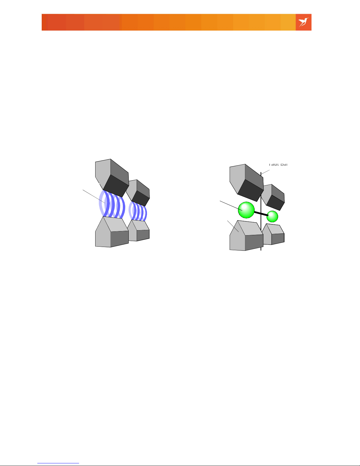
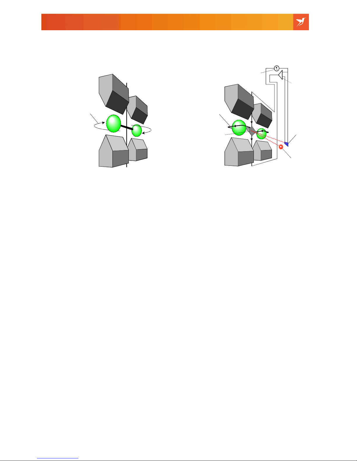
2HUMMINGBIRD PARAMAGNETIC MEASUREMENT PRINCIPLE..................................4
3PRODUCT SPECIFICATION ...........................................................................................6
3.1 PERFORMANCE SPECIFICATION (UNDER CONSTANT CONDITIONS) ........................................6
3.2 MECHANICAL SPECIFICATION ...........................................................................................7
3.3 EXTERNAL POWER SUPPLY SPECIFICATION.......................................................................8
3.4 ENVIRONMENTAL SPECIFICATION .....................................................................................8
4SENSOR INTEGRATION............................................................................................... 10
4.1 SENSOR MOUNTING......................................................................................................10
4.2 ELECTRICAL ARRANGEMENT .......................................................................................... 13
4.3 ANALOGUE OUTPUT......................................................................................................14
4.4 LOCATION OF SENSOR .................................................................................................. 15
4.5 HOW TO MINIMISE EXPOSURE OF PNEUMATIC SYSTEM TO CONTAMINANTS......................... 15
4.6 HOW TO HANDLE THE SENSOR ...................................................................................... 15
4.7 ORIENTATION OF SENSOR ............................................................................................. 16
4.8CONDITIONING OF THE SAMPLE...................................................................................... 16
4.9 PRESSURE EFFECTS.....................................................................................................16
4.10 USE OF SENSOR WITH FLAMMABLE /TOXIC SAMPLE GASES..............................................18
5OPERATION AND CALIBRATION ................................................................................18
5.1 CALIBRATION –INITIAL CONDITIONS ...............................................................................18
5.2 SINGLE POINT OFFSET CORRECTION (SPOC).................................................................18
5.3 ZERO DRIFT OFFSET CORRECTION IN THE HOST EQUIPMENT............................................22
5.4 LED SENSOR STATUS ...................................................................................................22
6VARIANTS, SPARES, PACKAGING AND WARRANTY ...............................................23
6.1 SENSOR VARIANTS OPTIONS –AS SHIPPED FROM HUMMINGBIRD ......................................23
6.2 PRODUCT SPARES........................................................................................................23
6.3 SPECIAL PACKAGING .................................................................................................... 23
6.4 PRODUCT FAILURE DURING WARRANTY..........................................................................24
6.5 PRODUCT FAILURE OUT OF WARRANTY ..........................................................................24
6.6 MAINTENANCE AND SERVICING ...................................................................................... 24
6.7 DECONTAMINATION.......................................................................................................24
6.8 ROHS AND WEEE DIRECTIVES .....................................................................................25
7APPENDICES................................................................................................................26
APPENDIX 7.1 OUTLINE DIMENSIONS,KK FRICTION LOCK CONNECTOR............................... 26
APPENDIX 7.2 OUTLINE DIMENSIONS,SMT LOW PROFILE CONNECTOR .............................. 27
APPENDIX 7.3 PROCEDURE FOR FIXING OF THE ADAPTOR PLATE........................................28
APPENDIX 7.4 MECHANICAL VIBRATION AND SHOCK RESISTANCE ....................................... 29
APPENDIX 7.5 SAMPLE GAS CROSS SENSITIVITY GUIDE .................................................... 30
APPENDIX 7.6 ROHS II DIRECTIVE 2011/65/EU DECLARATION ..........................................33

3 of 35 01115009A _9
Paracube
®
Micro – Instruction Manual
1 Introduction
The Paracube®Micro represents the latest generation of Hummingbird’s paramagnetic
sensing technology. The sensor takes advantage of recent technological advances
allowing a performance only previously available from sensors of much greater size
and cost.
The sensor offers the OEM true flexibility in both mechanical and communication
interfaces incorporating Hummingbird’s world renowned paramagnetic technology
which has been designed into many OEM products where reliability, long life and
performance are major considerations.
Hummingbird’s non-depleting paramagnetic technology ensures consistent
performance over time with added cost-of-ownership benefits. The selectivity of the
measurement to oxygen means there is no interference from other respiratory gases.
The sensor provides a stable oxygen measurement, which is inherently linear and only
requires a single reference gas to perform a full calibration. There is no requirement for
a reference gas during operation.
Note - No. 1
This Paracube®manual details the operation and installation of the
Analogue variants only.
A full listing of all Paracube®Micros, including the Digital variants,
can be found in Section 6.1. The manual detailing the Digital
variants can be ordered under part number 01115001A.

4 of 35 01115009A _9
Paracube
®
Micro – Instruction Manual
2 Hummingbird Paramagnetic Measurement Principle
The sensor utilises the paramagnetic susceptibility of oxygen, a physical property
which distinguishes oxygen from most other common gases.
The sensor incorporates two nitrogen-filled glass spheres mounted on a strong, noble
metal taut-band suspension. This assembly, termed the ‘Suspension Assembly’ is
suspended in a symmetrical non-uniform magnetic field. When the surrounding gas
contains paramagnetic oxygen, the glass spheres are pushed further away from the
strongest part of the magnetic field. The strength of the torque acting on the
suspension is proportional to the oxygen content of the surrounding gases.
Fig.1
The measuring system is ‘null-balanced’. The 'zero' position of the suspension
assembly, as measured in nitrogen, is sensed by a differential photo-sensor assembly
that receives light reflected from a mirror attached to the suspension assembly. The
output from the photo-sensor is processed and then fed back to a coil wound around
the suspension assembly to achieve a ‘null balanced’ position. This feedback achieves
two objectives:
When oxygen is introduced to the cell, the torque acting upon the suspension
assembly is balanced by a restoring torque due to the feedback current in the coil. The
feedback current is directly proportional to the volume magnetic susceptibility of the
sample gas and hence, after calibration, to the partial pressure of oxygen in the
sample. A voltage output is derived which is proportional to the feedback current.
Taut Band
Permanent
Magnet
N2 filled
Spheres
Magnetic Field

5 of 35 01115009A _9
Paracube
®
Micro – Instruction Manual
Fig.2
In addition, the electromagnetic feedback stabilises the suspension (heavily damping
oscillations) thus making it resilient to shock and vibration.
Rotation
Mirror
Light Source
Photodiodes
C
urrent M
easurement
Conductive
W
ire
Amplifier

6 of 35 01115009A _9
Paracube
®
Micro – Instruction Manual
3 Product Specification
3.1 Performance Specification (under constant conditions)
This specification applies when the sensor has been calibrated using standard gas
values of N2and 100% O2 using the calibration procedure described in Section 5.
Unless otherwise stated, the performance figures quoted are derived from two
standard deviation analysis. Where marked (†) testing has been conducted in
accordance with the requirements of IEC 61207-1 1994.
Operating Range
0 to 100% O2 with over range capability -15% O2to +200% O2
Intrinsic Error†
<±0.2% O2.
Linearity†
<±0.2% O2.
Repeatability†
<±0.2% O2.
Signal Noise (peak to peak)†
<0.2% O2.
Zero Stability (permanent drift from calibration value)†
<±0.4% O2for first 24 hours.
<±0.2% O2for the subsequent week (additional).
<±0.2% O2per month thereafter (additional).
Temperature Coefficient
Zero: <±0.5% O2/ 10oC.
Span: <±0.5% of O2reading / 10oC.
Response Time in Seconds (tested under Hummingbird test conditions using a 1
micron filter).
Flow Rate Flow Parallel
to Manifold
Gas
Concentration
250mL.min-1 18 16%-21%
250mL.min-1 20 Air-100%
500mL.min-1 11 16%-21%
500mL.min-1 13 Air-100%
2000mL.min
-
1
11 16%-21%

7 of 35 01115009A _9
Paracube
®
Micro – Instruction Manual
Pressure Range
±33kPag (±5psig), operating
±66kPag (±10psig), proof
±100kPag (±15psig), failure
Tilt
<±0.5% O2equivalent for 15° change in orientation from the calibration point
Time to Valid Reading
Time to valid output (from power up when within environmental spec) <8 seconds
Time to status output (from power up when outside environmental spec) <8 seconds
Pressure Compensation
<0.8% of reading for 20kPag (±3psig), change from calibration point.
3.2 Mechanical Specification
Dimensions (W X D X H)
The sensor can be supplied with a choice of two electrical connectors which modifies
its height ‘H’ as follows:-
Low profile SMT connector
33.5mm x 30mm x 37.6mm (imperial dims. 1.32” x 1.18” x 1.48”).
Type KK friction lock connector
33.5mm x 30mm x 46.1mm (imperial dims. 1.32” x 1.18” x 1.81”).
For full outline dimensions refer to appendix 7.1 and 7.2.
Weight
70 grams (2.47 ounces).
Pneumatic Leakage
3x10⁻⁴ mbar.L.sec-1 (~3x10⁻⁴ SCCS).
Gas Interface
Diffusion: hydrophobic 1 micron pore-size filter fitted as standard (biological filter
grades available on request).
Sealed using an ‘O’ ring (BS4518, part no. 0181-16).

8 of 35 01115009A _9
Paracube
®
Micro – Instruction Manual
Materials in Contact with Sample Gas
Stainless steel grades 316, 316L, 302S25 and 304 (1.4301).
Borosilicate glass and alkali borosilicate glass.
Polyphenylene sulphide (PPS) with carbon / glass filler.
Polysulphone (UDEL).
Platinum and platinum iridium alloy.
Nickel.
Fluorocarbon elastomer -FPM (Viton).
Krytox GPL205 grease.
PTFE filter.
Polypropylene.
3.3 External Power Supply Specification
+5V dc ±5%, a supply supervisor inhibits operation when the PSU is below 4.75V.
Ripple and noise <0.1V Pk to Pk.
Current consumption: 5V supply rail = 70mA typical 100mA max.
A change of ±0.25V in supply Voltage results in a change of less than ±0.1% in oxygen
concentration.
3.4 Environmental Specification
Sample Gas Condition
Dry, non-corrosive, non-flammable gas, free of entrained oil, less than 3 micron
particulates, non-condensing, dew point 10°C below the sensor operating temperature.
Pressure Effect
The oxygen output will change in direct proportion to the barometric pressure unless
pressure compensation is enabled (see variant options, table 7).
Operating Temperature
5°C to 50°C (41°F to 122°F).
Storage Temperature (non-condensing conditions)
-30°C to +70°C (-22°F to 158°F).
Storage Pressure
10kPa – 200kPa (1.5psi - 30psi).
Thermal Time Constant
15 minutes. Time required for the O2signal to reach 66% of final reading when the
sensor has been subjected to a 20°C step change in ambient temperature.
Ambient Humidity
0 to 95% RH.
Altitude Range (operating)
-500m to +5000m (-1540ft to +15400ft).

9 of 35 01115009A _9
Paracube
®
Micro – Instruction Manual
Shock and Vibration
Meets the requirements of BS EN 60068-2-6:1996 (IEC 68-2-6), BS EN 600-2-27:1993
(IEC 68-2-27) and IEC 68-2-34. Details of these requirements are given in Appendix
7.4.
Soft Magnetic Material
A change in the reading of <0.1% O2will occur when a soft magnetic material is
brought within 10mm of the sensor body.
Interference Effects
The paramagnetic effect of common background gases at 20oC, for 100%
concentration is shown below:
Interfering Gas
Interference Effect
(100% Interferent)
(% O2)
N2O -0.20
CO2-0.26
H2O -0.03
Methane -0.16
CO 0.06
Helium 0.29
NO 42.56
NO2 5.00
A comprehensive list detailing the effect of other background gases is outlined in
Appendix 7.5 or in Hummingbird Application Note HBAN PM 25 (available on request).

10 of 35 01115009A _9
Paracube
®
Micro – Instruction Manual
4 Sensor Integration
4.1 Sensor Mounting
The sensor may be mounted using Method 1 or Method 2, if it is being mounted to an
electrically non-conductive surface and Method 3 if it is being mounted to an
electrically conductive surface, described below :-
Fig. 3
Method 1
Secure the sensor with the M2 inserts moulded into the sensor body in a triangular
arrangement using insert Nos. 1, 3 and 4 or a linear arrangement using insert Nos. 2
and 4. The insert numbers are labelled in fig. 3 above. Fixing screws should be chosen
on the basis that 3mm +/-0.5m of thread engagement is made with the inserts.
To ensure no damage occurs to the sensor or to the host equipment and to ensure that
a reliable gas tight seal is produced, observe Caution 2 and 3.
CAUTION
-
No. 1
It is recommended that the sensor be mechanically mounted to an
electrically non-conductive surface. However, where installation
dictates mounting to a conductive surface, the sensor MUST be
electrically isolated from the host by means of the “Adaptor Plate”,
spares part number 01115933, see Appendix 7.3.

11 of 35 01115009A _9
Paracube
®
Micro – Instruction Manual
Method 2
Secure the sensor using the four clearance holes located at the corner of sensor
moulding, again shown in Fig. 4. This method recommends using M2 hexagon socket
cap screws in conjunction with a “Ball ended” Allen key due to the shallow approach
that must be made by the fixing tool. To ensure that a reliable gas tight seal is
produced, observe Caution No. 3.
Fig. 4
CAUTION
–
No. 3
To ensure a gas tight seal the fixing screws should be tightened to
a torque value of 0.30 to 0.35 Nm.
CAUTION
-
No. 2
When using method 1 to install the Paracube®Micro it is important
to note that the maximum insertion depth for the fixing screws is
3.5mm.

12 of 35 01115009A _9
Paracube
®
Micro – Instruction Manual
Method 3
If the sensor is being mounted to an electrically conductive surface it MUST be
electrically isolated from the host by means of the “Adaptor Plate Kit”, spares part
number 01115933. This kit must be ordered separately, but will be shipped in the same
packing as the sensor if required.
The adaptor plate is fixed to the sensor via 4 off M2 x 8mm long hex’ socket cap
screws. These screws are to be tightened in a diagonal fashion and to a torque value
of between 0.30 and 0.35Nm. Ensure the sensor’s original ‘O’ ring remains in position
before fixing the adaptor plate, see Fig 4A. For full details to fixing of the adaptor plate,
refer to Appendix 7.3.
Once the adaptor plate is properly fixed to the sensor, place the ‘O’ ring supplied with
the kit into the ‘O’ ring groove identified in Fig 4B. Secure the sensor as described in
Method 1 using the equivalent of fixing points 2 and 4 from Fig. 3 above.
Fig. 4A Fig. 4B
All three methods provide a reliable means of mounting the sensor to the host
equipment. The options are designed to accommodate a wide variety of customer
mounting requirements. Refer to Appendix 7.1 and 7.2 for positional and dimensional
details.
In order to achieve a reliable seal, both fixing methods must use the Viton®‘O’ ring seal
supplied with the sensor (BS4518 size 0181-16). The host interface must be flat and
meet the surface roughness values of 0.8 microns as defined by standard
BS4518. If the sensor is removed from its host fixing, the ‘O’ ring must be checked for
signs of degradation or compression set. If this occurs, the ‘O’ ring must be discarded
and replaced with a new Viton®‘O’ ring to the same specification as supplied.

13 of 35 01115009A _9
Paracube
®
Micro – Instruction Manual
4.2 Electrical Arrangement
Power Supply (to be provided by the OEM)
The sensor requires an external power supply as specified in Section 3.3.
Electrical Connection
Connection to the sensor is made via a 4 way connector mounted onto the sensor’s
PCB. There are two connector types offered as standard, a Molex KK type friction lock
(Fig. 5) or a low profile SMT connector (Fig. 6). See Table 1 for pin out details. Full
details of the sensor variants are detailed in Section 6.1.
All electrical connections to the sensor must be made using the correct style of ‘Molex’
connector, website www.molex.com
PCB Mounted KK Friction Lock Connector - Molex Part No 0022272041, Fig. 5
2.54mm (.100") Pitch KK® Wire-to-Board Header, Vertical, with Friction Lock.
Mating crimp housing required by end-user Molex part number 0022012045 used in
conjunction with crimp terminal part number 0008500032.
Fig 5
CAUTION
–
No. 4
The four screws securing the outer most PCB are factory fitted and
should not be removed or used for mounting purposes
WARNING USE
-
No. 1
FAILURE TO FOLLOW THE RECOMMENDED PROCEDURE FOR FIXING OF THE
SENSOR MAY RESULT IN LEAKS EXPOSING PERSONNEL TO THE SAMPLE
GASES.

14 of 35 01115009A _9
Paracube
®
Micro – Instruction Manual
PCB Mounted SMT Connector - Molex No 532610471, Fig. 6
1.25mm (.049") Pitch PicoBlade™ Header, Surface Mount, Right Angle.
Mating crimp housing required by end-user Molex part number 0510210400 used in
conjunction with crimp terminal part number 0500798000.
Fig. 6
P1 P2 P3 P4
+5V Analogue mV Signal Analogue 0V Earth/Ground
Table 1
Connector Details
Pins 1 and 4 (P1 and P4) shown in table 1 above are used to supply power to the
sensor, pins 2 and 3 (P2 and P3) provide the sensor’s mV output.
Earthing Arrangement
The sensor does not require an external earth connection. Electrostatic potentials are
discharged via the power supply 0V connection.
Electrical Separation
The electrical connections to the sensor should be kept to a minimum length. The
cable should be of a shielded 4-core construction; connect the electrical screen to the
equipment chassis earth star point.
4.3 Analogue Output
The analogue output is provided via the processor’s DAC and updates the reading
every 200ms +/- 5ms (5 readings every second). The analogue output is a differential
measurement between analogue 0V (Pin3) and analogue mV signal (Pin2). Do not
connect analogue 0V (Pin3) and Earth / Ground (Pin4) together as any contact
resistance will introduce offsets to the analogue signal.
The host equipment must provide an input impedance of >1MΩ

15 of 35 01115009A _9
Paracube
®
Micro – Instruction Manual
The sensor is configured to provide a scaled analogue output in one of two voltages as
follows;
1. Scaled output of 0.5mV/%O2, equivalent to 0- 50mv for 0% to 100% oxygen –
Variants 01115704, 01115705, 01115710, 01115711 and 01115714.
2. Scaled output of 10mV/%O2, equivalent to 0- 1v for 0% to 100% – Variants
01115706, 01115707, 01115712, 01115713 and 01115715.
If the sensor is operated outside of its environmental specification the analogue output
will go to -15% O2(-0.15 volts for the 10mV/%02range and -7.5mV for the 0.5mV/%02
range).
If the sensor detects an electrical or sensing element malfunction or the sensor is
exposed to extreme temperatures the analogue output will go to the supply rail voltage
(+5V dc ±5%).
4.4 Location of Sensor
The sensor body should be fixed rigidly to the OEM assembly and away from vibrating
components and, in particular, care should be taken to avoid mounting the sensor onto
a chassis or plate that may act as a lever or spring. If the OEM equipment is subjected
to excessive mechanical shocks and vibration during use, it may be necessary to
mount the sensor on shock absorbers to dampen the impact to the output of the
sensor.
The sensor should be protected from sudden temperature variations, such as from
cooling fans, as this can affect the sensor’s calibration. Fitting the sensor into a
temperature controlled environment will eliminate varying environmental conditions and
optimize its performance.
4.5 How to Minimise Exposure of Pneumatic System to Contaminants
Keep the components of the pneumatic system, whether in the laboratory or in the
production assembly area, away from the ‘dirty’ operations, such as drilling, packaging,
filing, cutting, deburring and finishing.
Assemble components in a clean environment and ensure all the components in the
sample line tubing have been cleaned for oxygen service and are bagged immediately
after cleaning.
4.6 How to Handle the Sensor
Carefully remove the sensor body from the anti-static packaging and only handle the
sensor using anti-static handling procedures.
Do not remove the self-adhesive dust cover until the sensor is ready to be fitted in the
host equipment.
The sensor should be fitted into the OEM equipment under clean conditions in order to
minimise the likelihood of contaminants entering the sensor or the OEM system.

16 of 35 01115009A _9
Paracube
®
Micro – Instruction Manual
4.7 Orientation of Sensor
To achieve optimum performance, the sensor should be operated in the orientation of
calibration. Any small offsets resulting from a change in orientation may be removed by
performing a single point offset correction.
4.8 Conditioning of the Sample
Due to the inherent protection offered by the filter at the gas exchange interface,
sample conditioning can be kept to a minimum. The sensor’s hydrophobic filter will
prevent particulates larger than 1 micron and water from entering the measurement
cavity.
It is however good practice to reduce particulate contamination of the sample gas to
less than 3 microns to prevent blockage.
Sample Temperature
Condensation within the sensor may be avoided by ensuring that the sensor
temperature is at least 10°C above the sample gas dew point.
4.9 Pressure Effects
The sensor is a partial pressure device and variations in sample gas pressure will
cause fluctuations in the observed oxygen output, proportional to the pressure change.
Under these circumstances the following methods may be employed to mitigate this
effect.
Method 1 – with Sensor’s On-board Pressure Compensation Disabled
Precise control of the sample stream pressure can be adopted by the end user. This
applies particularly to pneumatic systems where the sensor is not vented directly to
atmosphere, and where restrictions in the sample exhaust will cause the sample back
pressure to vary with sample flow, resulting in oxygen reading errors.
This method is only applicable if the sensor forms part of the sealed sample stream,
which is independent of ambient pressure swings.
Method 2 - with Sensor’s On-board Pressure Compensation Enabled
By employing the sensor’s on-board pressure compensation and by selecting the
correct variant for the application the oxygen reading is automatically corrected
internally with no further action required by the end user. For barometric pressure
compensation, select variant 01115704, 01115705, 01115706 or 01115707. For
sample pressure compensation select variant 01115710, 01115711, 0111512 or
01115713.
CAUTION
–
No. 5
The sensor has exposed electronics which are at risk from
Electro-Static Discharge (ESD). Only handle the sensor in a
static safe environment.

17 of 35 01115009A _9
Paracube
®
Micro – Instruction Manual
The accuracy of error correction achieved by pressure compensation is detailed in
Section 3.1.
Method 3 – with Sensor’s On-board Pressure Compensation Disabled
In some cases it may be desirable for the end user to perform their own pressure
compensation. During sensor calibration, the span gas value and pressure reading
should be recorded. These values may then be used to correct the oxygen signal for
changes in sample pressure (if sensor is housed in a closed sample system) or
barometric pressure (if sensor is open to ambient conditions) according to the following
formula:
Where:
% O2 comp : Compensated O2value
% O2 ind: Current O2value
Pcal : Calibration pressure
Pind : Current pressure
⎥
⎦
⎤
⎢
⎣
⎡
×
=
ind
cal
ind
Comp P
P
OO 2
2
%
%
CAUTION
–
No. 7
If pressure compensation is toggled between its two operational
states a ‘C’ flag will appended to the output indicating a two point
calibration is required to ensure a valid oxygen reading.
CAUTION
–
No. 6
Pressure compensation is factory configured to measure internal
(sample gas) or external (barometric) pressure. Selecting the right
product variant for the application is essential if compensation is to
be applied correctly. The compensation is not interchangeable.
N
ote
-
No. 2
Users of variants 01115714, 01115715, 01115716 and 01115717
should refer to section 5 for guidance on how to provide their own
pressure compensation.
Table of contents
Popular Accessories manuals by other brands

NTI
NTI ENVIROMUX Series Installation and operation manual

Frank van Dijk Trading
Frank van Dijk Trading V069 instruction manual

Paramount Fitness
Paramount Fitness Ultra UV2 Replacement manual

Olimpia splendid
Olimpia splendid PELER 10 WIFI Instructions for use and maintenance

EVE
EVE door & window 20EAL9901 Get started

Gewiss
Gewiss Chorus GW 10 611 quick start guide