manuals.online logo
Brands
  1. Home
  2. •
  3. Brands
  4. •
  5. Bouclair
  6. •
  7. Indoor Furnishing
  8. •
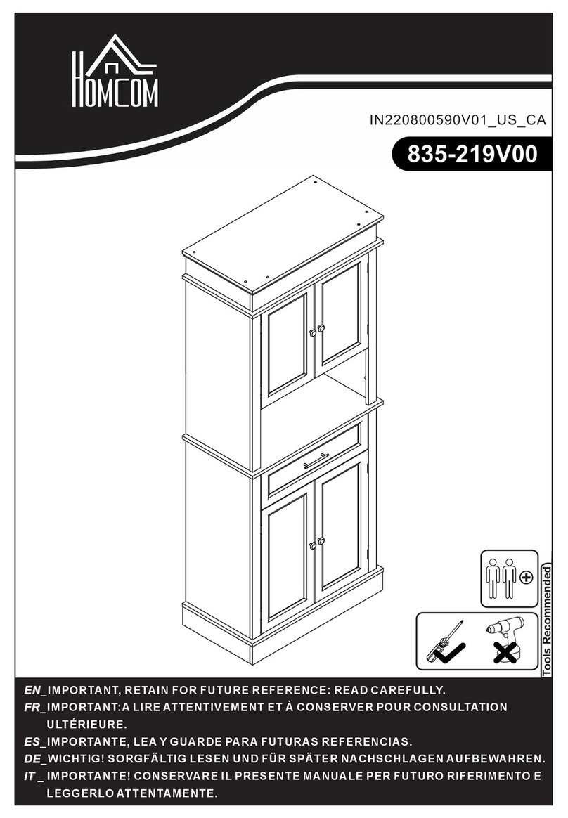
  9. Bouclair 9389564 User manual

Bouclair 9389564 User manual

INSTRUCTIONS D'ASSEMBLAGE
ASSEMBLY INSTRUCTIONS
LISTE DES PIÈCES
PARTS LIST
APANNEAU SUPÉRIEUR
TOP PANEL 1
9389564
ARTICLE:
ITEM:
BPANNEAU LATÉRAL
SIDE PANEL 1
CPANNEAU LATÉRAL
SIDE PANEL
DPANNEAU D’APPUI
SUPPORT PANEL 1
EPANNEAU D’APPUI
SUPPORT PANEL 1
FPANNEAU INFÉRIEUR
BOTTOM PANEL
GPANNEAU ARRIÈRE
BACK PANEL
HTABLETTE
SHELF
IPANNEAU AVANT DU TIROIR
FRONT DRAWER PANEL 2
JPANNEAU LATÉRAL DU TIROIR
SIDE DRAWER PANEL
1
11
3
2
PIÈCE
PC
PIÈCE
PC
PIÈCE
PC
PIÈCE
PC
PIÈCE
PC
PIÈCE
PC
PIÈCES
PCS
PIÈCE
PC
PIÈCES
PCS
PIÈCES
PCS
1 SUR/OF 8
LISTE DES PIÈCES
PARTS LIST
116
VIS
SCREW
ÉCROU
LOCK NUT
2
3
4
CHEVILLE DE BOIS
WOOD DOWEL
5
24
VIS
SCREW
6
20
VIS
SCREW
7
VIS
SCREW
8
VIS
SCREW
9
VIS
SCREW
10
11
4
SUPPORT À TABLETTE
SHELF PIN
12
4
CAPUCHON
CAP
COLLE
GLUE
CLÉ HEXAGONALE/TOURNEVIS
ALLEN KEY/SCREWDRIVER 1
KPANNEAU LATÉRAL DU TIROIR
SIDE DRAWER PANEL 2
LPANNEAU ARRIÈRE DU TIROIR
REAR DRAWER PANEL 2
MFOND DU TIROIR
BOTTOM DRAWER PANEL 2
NCADRE LATÉRAL
SIDE FRAME 2
OBARRE TRANSVERSALE
CROSS BRACE 2
PPOIGNÉE
HANDLE
QGLISSIÈRE DE GUIDANCE
SLIDE RAIL 2
RGLISSIÈRE DE GUIDANCE
SLIDE RAIL 2
SGLISSIÈRE DE GUIDANCE
SLIDE RAIL 2
TGLISSIÈRE DE GUIDANCE
SLIDE RAIL 2
PIÈCES
PCS
PIÈCES
PCS
PIÈCES
PCS
PIÈCES
PCS
PIÈCES
PCS
PIÈCES
PCS
PIÈCES
PCS
PIÈCES
PCS
PIÈCES
PCS
PIÈCES
PCS
PIÈCES
PCS
PIÈCES
PCS
PIÈCES
PCS
PIÈCES
PCS
PIÈCES
PCS
PIÈCES
PCS
PIÈCES
PCS
PIÈCES
PCS
PIÈCES
PCS
PIÈCES
PCS
PIÈCE
PC
PIÈCE
PC
1
16
8
4
4
6
2
2 SUR/OF 8
ÉTAPE / STEP 1
ÉTAPE / STEP 2
ÉTAPE 1 :
1. Fixez les deux barres transversales (O) aux deux cadres latéraux (N) à l'aide de quatre vis (7). Serrez les vis à l'aide de
la clé hexagonale/tournevis (12).
2. Insérez les capuchons (10) dans les trous dans les cadres latéraux (N).
STEP 1:
1. Attach 2 x crossbars (O) to 2 x side frames (N), using 4 x screws (7). Tighten with the Allen key/screwdriver (12).
2. Insert 4 x caps (10) into 2 x side frames (N).
ÉTAPE 2 :
1. Appliquez de la colle (11) sur huit goujons en bois (3) et insérez-les dans le panneau supérieur (A).
2. Insérez huit vis (1) dans le panneau supérieur (A). Serrez les vis à l'aide de la clé hexagonale/tournevis (12).
STEP 2:
1. Apply glue (11) to 8 x wood dowels (3) and insert them into the top panel (A).
2. Insert 8 x screws (1) into the top panel (A). Tighten with the Allen key/screwdriver (12).
13
1
3
13
13
1
3
1
3
1
3
13
A
10
10
10
7
7
7
O
N
N
3 SUR/OF 8
ÉTAPE / STEP 3
ÉTAPE / STEP 4
ÉPATE 3 :
1. Fixez les deux glissières de guidance (Q) au panneau latéral (B) et au panneau de soutien (E) à l'aide de six vis (4).
Serrez les vis à l'aide de la clé hexagonale/tournevis (12).
2. Fixez les deux glissières de guidance (S) au panneau latéral (C) et au panneau de soutien (D) à l'aide de six vis (4).
Serrez les vis à l'aide de la clé hexagonale/tournevis (12).
STEP 3:
1. Attach 2 x slide rails (Q) to the side panel (B) and to the support panel (E), using 6 x screws (4). Tighten with the Allen
key/screwdriver (12).
2. Attach 2 x slide rails (S) to the side panel (C) and to the support panel (D), using 6 x screws (4). Tighten with the Allen
key/screwdriver (12).
ÉTAPE 4 :
1. Appliquez de la colle (11) sur les goujons (3) et poussez les panneaux latéraux (B et C) et les panneaux de soutien (D et E) sur les
extrémités des goujons et des vis dans le panneau supérieur (A). Fixez en insérant huit écrous (2) dans les trous dans les panneaux (B, C,
D et E). Serrez les écrous à l'aide de la clé hexagonale/tournevis (12).
2. Glissez un panneau arrière (G) dans la rainure dans le panneau latéral (B) et le panneau de soutien (D).
3. Glissez un panneau arrière (G) dans la rainure dans le panneau latéral (C) et le panneau de soutien (E).
4. Glissez un panneau arrière (G) dans la rainure dans le panneau de soutien (D) et le panneau de soutien (E).
STEP 4 :
1. Apply glue (11) to the dowels (3) and push 2 x side panels (B and C) and 2 x support panels (D and E) onto the protruding end of the
screws and the dowels in the top panel (A). Secure by inserting 8 x lock nuts (2) into the holes in the panels (B, C, D et E). Tighten with the
Allen key/screwdriver (12).
2. Slide 1 x back panel (G) into the groove in the side panel (B) and the support panel (D).
3. Slide 1 x back panel (G) into the groove in the side panel (C) and the support panel (E).
4. Slide 1 x back panel (G) into the groove in the support panel (D) and the support panel (E).
4
4
4
4
B
C D
E
S S
Q
Q
C
E
D
B
G
G
G
2
2
4 SUR/OF 8
ÉTAPE / STEP 5
ÉTAPE / STEP 6
ÉTAPE 6 :
1. Fixez une glissière de guidance (R) au panneau latéral du tiroir (J) à l'aide de trois vis (4). Serrez les vis à l'aide de la clé
hexagonale/tournevis (12).
2. Fixez une glissière de guidance (T) au panneau latéral du tiroir (K) à l'aide de trois vis (4). Serrez les vis à l'aide de la clé
hexagonale/tournevis (12).
3. Répétez pour le deuxième tiroir.
STEP 6:
1. Attach 1 x slide rail (R) to 1 x side drawer panel (J), using 3 x screws (4). Tighten with the Allen key/screwdriver (12).
2. Attach 1 x slide rail (T) to 1 x side drawer panel (K), using 3 x screws (4). Tighten with the Allen key/screwdriver (12).
3. Repeat for the second drawer.
ÉTAPE 5 :
1. Fixez le panneau inférieur (F) à la pièce assemblée à l'étape 4 à l'aide de douze vis (5). Serrez les vis à l'aide de la clé
hexagonale/tournevis (12).
STEP 5:
1. Attach the bottom panel (F) to the unit assembled in Step 4, using 12 x screws (5). Tighten with the
Allenkey/screwdriver (12).
5
5
5
5
F
C
E
D
B
J
K
R
T
4
4
5 SUR/OF 8
ÉTAPE / STEP 7
ÉTAPE / STEP 8
ÉTAPE 8 :
1. Insérez quatre vis (1) dans le panneau avant du tiroir (I). Serrez les vis à l'aide de la clé hexagonale/tournevis (12).
2. Insérez les extrémités des vis dans le panneau avant du tiroir (I) dans les trous dans les panneaux latéraux du tiroir (J et K). Fixez en
insérant quatre écrous (2) dans les trous dans les panneaux latéraux du tiroir (J et K). Serrez les écrous à l'aide de la clé
hexagonale/tournevis (12).
3. Fixez la poignée (P) au panneau avant du tiroir (I) à l'aide de deux vis (6). Serrez les vis à l'aide de la clé hexagonale/tournevis (12).4.
Répétez pour le deuxième tiroir.
STEP 8:
1. Insert 4 x screws (1) into the front drawer panel (I). Tighten with the Allen key/screwdriver (12).
2. Insert the protruding ends of the screws in the front drawer panel (I) into the holes in the side drawer panels (J and K). Secure by
inserting 4 x lock nuts (2) into the holes in the side drawer panels (J and K). Tighten with the Allen key/screwdriver (12).
3. Attach the handle (P) to the front drawer panel (I), using 2 x screws (6). Tighten with thw Allen key/screwdriver (12).
4. Repeat for the second drawer.
ÉTAPE 7 :
1. Fixez le panneau arrière du tiroir (L) aux panneaux latéraux du tiroir (J et K) à l'aide de quatre vis (5). Serrez les vis à l'aide
de la clé hexagonale/tournevis (12).
2. Glissez le fond du tiroir (M) dans la rainure des panneaux latéraux (J et K) et du panneau arrière (L) du tiroir.
3. Répétez pour le deuxième tiroir.
STEP 7 :
1. Attach 1 x rear drawer panel (L) to the side drawer panels (J and K), using 4 x screws (5). Tighten with the Allen
key/screwdriver (12).
2. Slide 1 x bottom drawer panel (M) into the groove in the side drawer panels (J and K) and in the rear drawer panel (L).
3. Repeat for the second drawer.
5
5
J
L
K
M
6
I
P
1
1
2
2
K
J
6 SUR/OF 8
ÉTAPE / STEP 9
ÉTAPE / STEP 10
ÉTAPE 10 :
1. Insérez quatre supports à tablette (9) dans les panneaux de soutien (D et E) à la hauteur souhaitée.
2. Déposez la tablette (H) sur les supports à tablette (9).
STEP 10:
1. Insert the shelf pins (9) into the support panels (D and E) at the desired height.
2. Place the shelf (H) onto the shelf pins (9).
ÉTAPE 9 :
1. Fixez le cadre assemblé à l'étape 1 à la pièce assemblée à l'étape 8 à l'aide de six vis (8). Serrez les vis à l'aide de la
clé hexagonale/tournevis (12).
STEP 9:
1. Attach the frame assembled in Step 1 to the unit assembled in Step 8, using 6 x screws (8). Tighten with the Allen
key/screwdriver (12).
88
8
9
9
H
D
E
7 SUR/OF 8
ÉTAPE / STEP 11
ARTICLE ASSEMBLÉ / ASSEMBLED TABLE
ÉTAPE 11 :
1. Glissez les deux tiroirs assemblés à l'étape 8 dans la pièce assemblée à l'étape 9 comme indiqué.
STEP 11:
1. Insert the two drawers assembled in Step 8 into the unit assembled in Step 9 as shown.
8 SUR/OF 8
QUESTIONS?
[email protected] - 1-800-268-2524

Other Bouclair Indoor Furnishing manuals
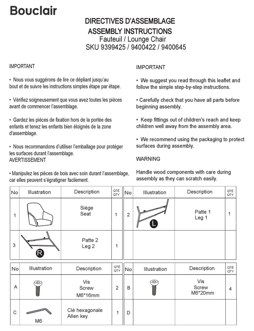
Bouclair 9397728 User manual

Bouclair

Bouclair 9397728 User manual

Bouclair 9398564 User manual

Bouclair

Bouclair 9398564 User manual

Bouclair 9401792 User manual

Bouclair

Bouclair 9401792 User manual

Bouclair 9400411 User manual

Bouclair

Bouclair 9400411 User manual

Bouclair 9397387 User manual

Bouclair

Bouclair 9397387 User manual

Bouclair 9387752 User manual

Bouclair

Bouclair 9387752 User manual

Bouclair 9400969 User manual

Bouclair

Bouclair 9400969 User manual

Bouclair Barcelona 9379023 User manual

Bouclair

Bouclair Barcelona 9379023 User manual

Bouclair 9385940 User manual

Bouclair

Bouclair 9385940 User manual

Bouclair 9400421 User manual

Bouclair

Bouclair 9400421 User manual

Bouclair 9401780 User manual

Bouclair

Bouclair 9401780 User manual

Bouclair 9403154 User manual

Bouclair

Bouclair 9403154 User manual

Bouclair 9397619 User manual

Bouclair

Bouclair 9397619 User manual

Bouclair 9400338 User manual

Bouclair

Bouclair 9400338 User manual

Bouclair 9399669 User manual

Bouclair

Bouclair 9399669 User manual

Bouclair 9393715 User manual

Bouclair

Bouclair 9393715 User manual
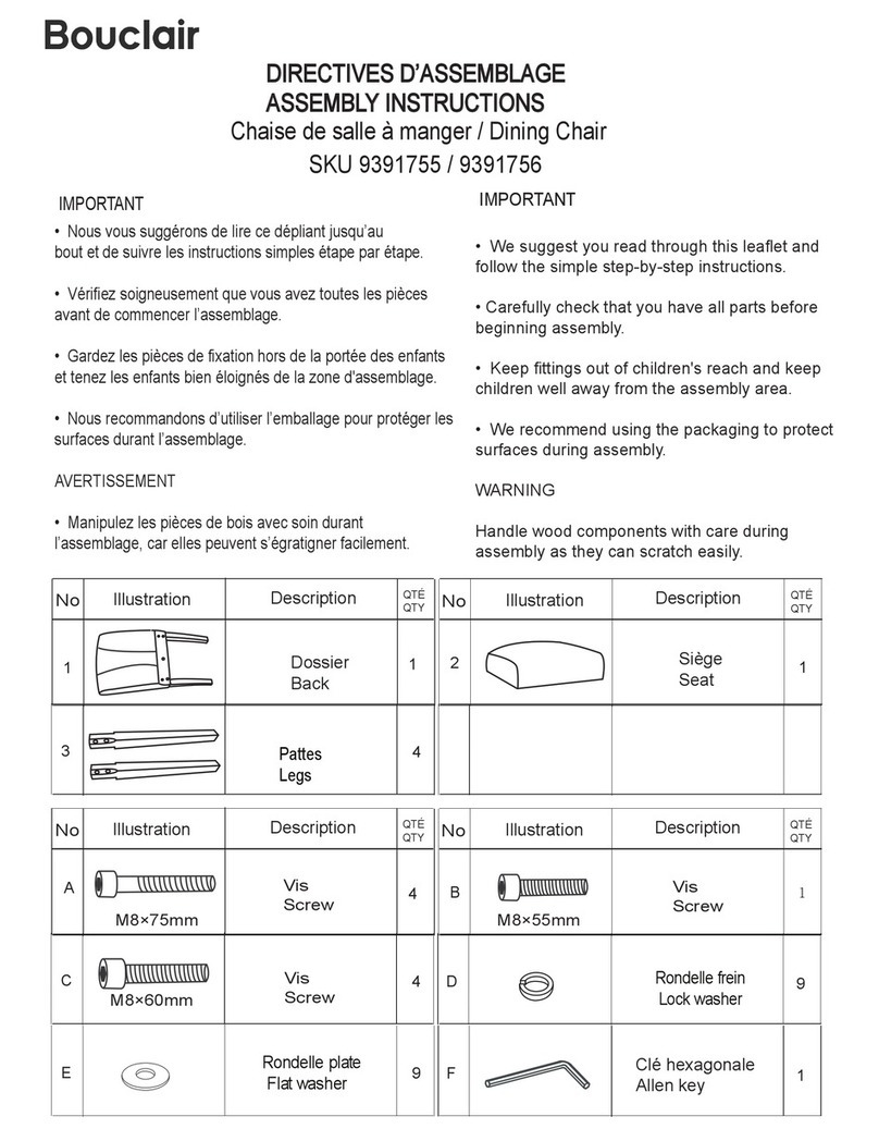
Bouclair 9403943 User manual

Bouclair

Bouclair 9403943 User manual
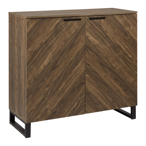
Bouclair 9400452 User manual

Bouclair

Bouclair 9400452 User manual

Bouclair 9400337 User manual

Bouclair

Bouclair 9400337 User manual

Bouclair 9401990 User manual

Bouclair

Bouclair 9401990 User manual

Bouclair 9399432 User manual

Bouclair

Bouclair 9399432 User manual

Bouclair 9391668 User manual

Bouclair

Bouclair 9391668 User manual

Bouclair 9399702 User manual

Bouclair

Bouclair 9399702 User manual

Bouclair 9393667 User manual

Bouclair

Bouclair 9393667 User manual

Popular Indoor Furnishing manuals by other brands
GFW MARIANNE TV UNIT Assembly instructions

GFW

GFW MARIANNE TV UNIT Assembly instructions

Klever Desk operating instructions

Klever

Klever Desk operating instructions

Lumi GMD02-1 instruction manual

Lumi

Lumi GMD02-1 instruction manual

m-Dimension 8626 Assembly instructions

m-Dimension

m-Dimension 8626 Assembly instructions

Triarch 31431-20 Assembly instructions

Triarch

Triarch 31431-20 Assembly instructions

MUMA ESCRITORIO VIGO Assembly instructions

MUMA

MUMA ESCRITORIO VIGO Assembly instructions

SERANO BG142 instruction manual

SERANO

SERANO BG142 instruction manual

Project Source 01715-1 manual

Project Source

Project Source 01715-1 manual

Zenith 9820CHSE Assembly instructions

Zenith

Zenith 9820CHSE Assembly instructions

Ametrix 36W Supplementary installation instructions

Ametrix

Ametrix 36W Supplementary installation instructions

Next ELKIN 354665 Assembly instructions

Next

Next ELKIN 354665 Assembly instructions

ECOPOSTURAL S4639 instructions

ECOPOSTURAL

ECOPOSTURAL S4639 instructions

Courtyard Creations TMS28JT Assembly instructions

Courtyard Creations

Courtyard Creations TMS28JT Assembly instructions

Coopers G626 Instructions for use

Coopers

Coopers G626 Instructions for use

John Thomas SH-7247X Assembly instructions

John Thomas

John Thomas SH-7247X Assembly instructions

Teknik Barrister Home 4 Drawer Chest Instruction booklet

Teknik

Teknik Barrister Home 4 Drawer Chest Instruction booklet

Us & Coutumes B3 Assembly instructions

Us & Coutumes

Us & Coutumes B3 Assembly instructions

IKEA BESTA UPPLAND ROLL FRONT 24X75" instructions

IKEA

IKEA BESTA UPPLAND ROLL FRONT 24X75" instructions

manuals.online logo
manuals.online logoBrands
  • About & Mission
  • Contact us
  • Privacy Policy
  • Terms and Conditions

Copyright 2025 Manuals.Online. All Rights Reserved.