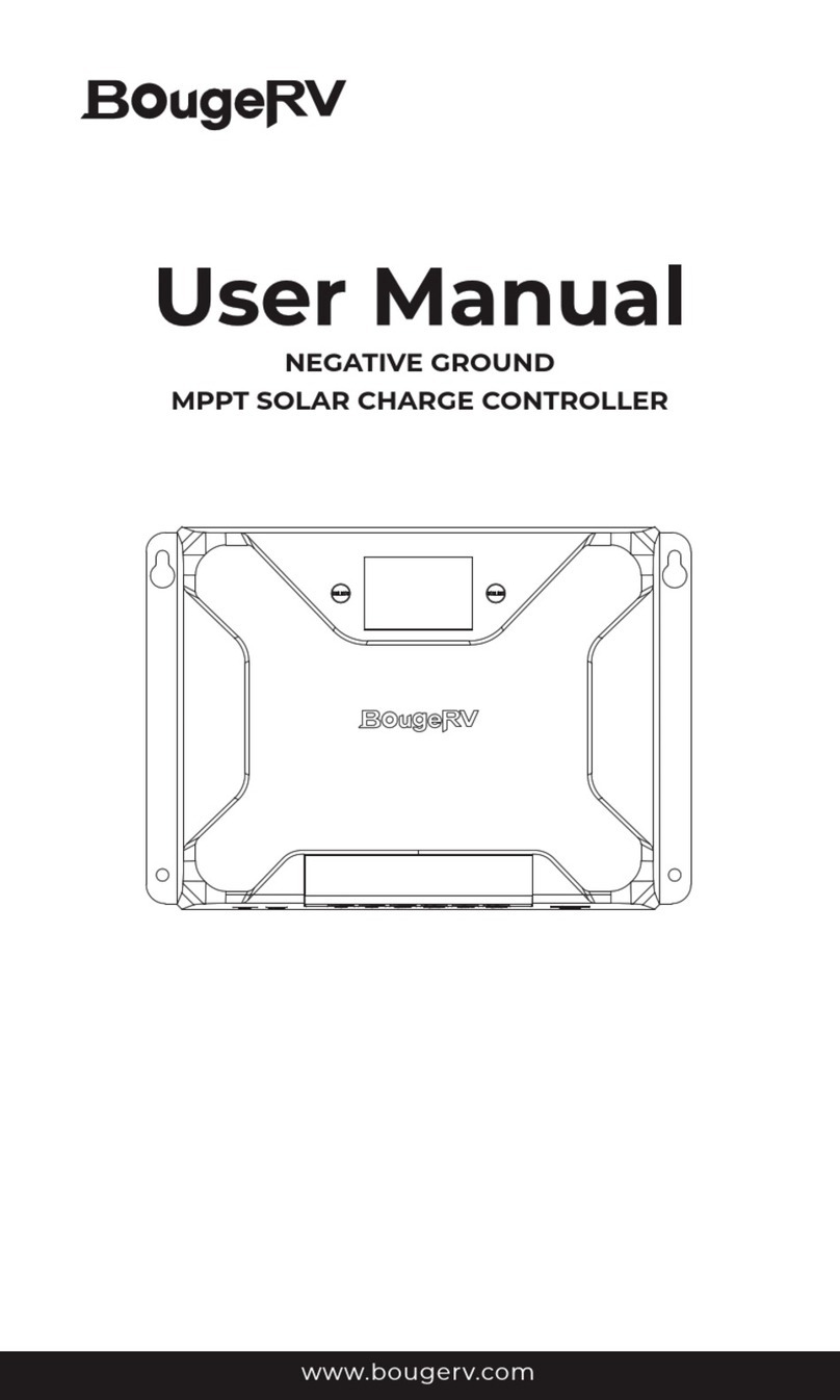
BougeRV PWM NEGATIVE GROUND User manual

PWM NEGATIVE GROUND
SOLAR CHARGE CONTROLLER
www.bougerv.com

Safety Instructions
Features
Technical After Services
Identification Of Parts
LCD Display Interface Overview
System Wiring
Wiring Instructions
Key Operation
LCD Display Interface
Error Code
Base Specification
Battery Charge Parameter
Controller Dimension
Lead-acid Battery Working Stage
Lithium Battery Working Stage
Frequently Asked Questions
1
2
3
4
5
6
7
8
9
12
13
14
15
18
19
20
Content

Please save these instructions
Safety Instructions
1.Read all of the instructions and cautions in the manual before
installation.
2.There are no repairable parts for this controller,do not disassemble or
attempt to repair the controller.
3.Keep the controller from the water.
4.Make sure all connections with controller are tight.
5.Please read the product installation steps to ensure all connections
are correct.
Please follow the safety instructions for operation, the damage caused
by not following the safety instructions shall be borne by the individual.
General Safety Information
1.NEVER connect the solar panel array to the controller without a
battery. The battery must be connected first.
2.Ensure input voltage does not exceed 55 Voc to prevent permanent
damage.
3.Ensure that the output current of the solar panel does not exceed the
rated charging current of the controller.
Charge Controller Safety
1 . Do NOT let the positive (+) and negative (-) terminals of the battery
touch each other.
2. Explosive battery gases may be present while charging.
Be certain there is enough ventilation to release the gases.
3. Be careful when working with large lead-acid
batteries. Wear goggles and have fresh water available in case there is
contact with the battery acid.
4. Over-charging and excessive gas precipitation may damage the
battery plates and activate material shedding on them. Too high of an
equalizing charge or too long of one may cause damage. Please
carefully review the specific requirements of the battery used in the
system.
Battery Safety
1

Features
1. 1.57*1.18inch (40*30mm) large backlit color screen (10A is black&white
screen).
2. Easier to check the working status of the battery with the function of
displaying the charging voltage and charging current alternately.
3. It is compatible with Li, SEL, FLD, AGM, GEL, LTO, and LFP batteries,
and auto-voltage identification is available for lead-acid batteries.
4. Built-in reverse connection protection, open-circuit protection,
high-temperature protection, and over-current/short-circuit protection,
which is all self-recovery type, with no damage to the controller.
5. Ultra-low heat generation, equipped with a heavy-duty heat sink,
ensures the maximum output of the controller.
6. With the USB output, maximum current up to 2A, supporting high
current charging of iPhone, iPad, and Android mobile phones and
other devices.
7. Complete multi-stage PWM charge management.
8. 32-bit high-speed master control chips.
2

BougeRV provides 1-on-1 Solar Solution.
If you have any questions during use, please feel free to contact us:
If you could provide the following relevant information to our email (
[email protected]) before contacting us; we can provide you with
technical support solutions faster.
(1)The connection method of the solar panels (series/parallel, quantity,
voltage, power).
(2)The voltage and battery type of the battery.
(3)The pictures or videos of the controller: battery voltage, battery
charging current, the output voltage of the solar panel.
1-669-232-7427
www.bougerv.com
1-669-232-7427
Technical After Services
Whataspp
3

LCD Backlit Display Screen
Menu Button (switch menu/adjust parameters)
Switch Button (control USB/adjust parameters)
PV Positive Terminal
PV Negative Terminal
Battery Positive Terminal
Battery Negative Terminal
Installation Mounting Holes
USB Output Port
Heat Sink
4
Identification Of Parts
1
3
2
8
10
9
4 5 6 7
1
2
3
4
5
6
7
8
9
10

LCD Display Interface Overview
Indicate And Warning
BAT Type
Display Section
Charge And USB Status
Parameter
Status
System Error
Indication
Voltage
Indication
On
OFF
12V
24V
12V System Voltage
24V System Voltage
System Error - Check Error Code
System Normally
Status Icon Indication Status Description
Day Night
And Charge
Indication
Battery
Indication
USB
Indication
On
On
On
Daylight Detected
No Daylight Detected
Solar Charging Battery
Battery Voltage is Hight
Battery Voltage is Middle
Battery Voltage is Low
USB On
USB Off
5

1. The positive and negative poles of the battery must be connected to
the battery terminals of the controller first.
2. Finally, connect the positive and negative poles of the solar panel to
the PV terminals of the controller.
Note: Please strictly follow the above sequence for connection,
otherwise the controller may be damaged. The disassembly sequence
is opposite to the wiring one.
Caution
1. First make sure your battery system is 12V or 24V.
2. Ensure that the maximum open-circuit voltage of the solar system
does not exceed 55V.
3. Ensure that the maximum output current of the solar panel does not
exceed rated current.(10A/20A/30A)
4. Ensure that the voltage of the solar panel is higher than the battery
voltage.
System Wiring
①②
6

1. Unscrew the screws.
(Counterclockwise)
2. Plug the cable into the correct
port.
3. Tighten the screws.(Clockwise)
Note:
During the wiring process, the
attached terminal block can be used
for connection. After stripping the
wire, put it into the terminal block and
squeeze it with a crimping pliers.
4. Check the wiring condition
Wiring Instructions
12
3 4
7

Key Operation
Function Key System Mode Operate Function
View Mode
View Mode
Set Mode
Set Mode
Long Press
(exceed 2s)
Short Press
Long Press
(exceed 2s)
Short Press
Long Press
(exceed 2s)
Short Press
Long Press
(exceed 2s)
Short Press
Enter SET mode
View Next Page
N/A
Switch USB
On/Off
Save Data & Exit
SET Mode
Adjust
parameter(Dec)
N/A
Adjust
parameter(Add)
Keep Down , Long press exceed 10s,Show F01 to
restore factory settings.
8

① b01=Sealed Lead Acid battery (SEL)
② b02=Absorbed Glass Mat battery(AGM)
③ b03=GEL battery(GEL)
④ b04=Flooded Lead Acid battery (FLD)
⑤ b05=LiFePO4 (LFP)
⑥b06=Ternary lithium battery (LI)
⑦b07=Lithium-Titanium-Oxide (LTO)
In the view mode, short press Ato jump to the
menu interface, long press Afor more than 2s until
the parameter flashes, short press A, Bto adjust,
after finishing the adjustment, long press Bfor
more than 2s to confirm the parameter.
Short press Ato jump to other interface or wait for
15s without operation it would automatically jump to
the main menu interface.
LCD Display Interface
Automatic loop
playback every 3s
Battery charging voltage Battery charging current
Main Menu Interface
Menu 1:Battery type setting
Setting method
9
A:
B:
The displayed value is the
actual voltage of the battery.

Menu 2:System voltage setting interface
Menu 3:Lithium battery charging voltage setting
①Automatically identify voltage (only applicable to the lead-acid battery);
②12V battery; ③24V battery
Long Press
Setting method: Same as above.
Setting method: Same as above.
Note: When the battery type is set to lead-acid battery b01-b04, the
system automatically recognizes the battery voltage by default. When
it is set to b05-b07, the system defaults to 12V, and the voltage needs
to be adjusted manually)
Note: This setting menu interface will only appear when the battery type
is set to b05-b07. Please manually adjust it according to your own
lithium battery charging voltage (the adjustment voltage range is
11V-15V). The system default value refers to the battery charge parameter.
Long Press
10

Menu 5:Display solar panel output voltage
Menu 6:Error Code
Note: The voltage value only can be read, but cannot be adjusted; this
voltage is the output voltage of the solar panel. In PWM working mode,
this voltage will be automatically adjusted to be the same as the battery
charging voltage, and the open-circuit voltage of the solar panel will be
displayed when not charging;
Menu 4:Display the current controller temperature
①°F;②°C
Setting method: Same as above.
Note: The system defaults to °F.
Long Press
11

Error Code
12
The positive and negative
connections of the battery
are reversed.
Error code Cause of failure
Normal.
Battery voltage is too low.
Battery voltage has exceeded
the controller limit.
The controller is below the
limit temperature
(-20°C/-4°F).
The output current of the
solar panel exceeds the
rated current of the
controller.
The input voltage of the
solar panel exceeds 55V.
The positive and negative
connections of the solar
panel are reversed.
The controller exceeds
operating temperature
limit(80°C/176°F).
Disconnect and reconnect
with correct wire polarity.
Solution
/
Check if the system voltage is
set correctly or turn off the
load and continue charging
until the battery voltage
reaches the recovery voltage.
Check if the system voltage is
set correctly.
Place the controller in a
suitable temperature
environment.
Reduce the power of the solar
panel system.
Reduce the voltage of the
solar panel system and the
voltage is lower than 55V to
recover.
Disconnect and reconnect
with correct wire polarity.
Ensure the controller is placed
in a well-ventilated cool, dry
environment.

Base Specification
Model
System voltage:
Rated charging current:
Maximum PV input voltage:
Maximum input of PV system:
Screen dimensions:
Screen type:
Backlight display time:
No-load loss:
Working temperature:
Protection level:
Altitude:
Net weight:
Dimensions: (inch)
Drill Hole Size: (inch)
10A 30A
0.3 lb (155g) 0.4 lb (185g) 0.8 lb(370g)
4.72*3.53*1.27 5.92*3.95*1.92
Black&White Color
150W/12V
300W/24V
450W/12V
900W/24V
P2410N
12V/24V
20A
5.51*3.74*1.27
0.12*0.07
Color
300W/12V
600W/24V
<55V
15s off without operation
8ma (12V), 12ma (24V)
-31°F~113°F(-35ºC ~ +45ºC)
IP32
≤3000m
1.57*1.18inch (40*30mm)
P2420N P2430N
13

Note:
①n=1 for 12V system; n=2 for 24V system;
②The parameters corresponding to the yellow font can be
modified (adjust range is 11-15V *n) and the other parameters
cannot be modified.
Battery Types SEL AGM GEL FLD LFP LI LTO
Equalizing Charge
Voltage
14.4V* n 14.4V* n 14.2V*n 14.6V*n 14.6V*n 12.4V* n
-
13.4V*n
- -
- -
- -
- -
- -
-- -
Boost Charge
Voltage
14.6V*n 14 .4V * n 14.8V*n
Boost Charge
Return Voltage 13.2V*n -
-
Equalization
Charge Time
Boost Charge
Time
2 hour 2 hour
2 hour 2 hour 2 hour 2 hour
--
Equalizing Charge
Interval 30 day 30 day
2 hour
30 day- -
Floating Charge
Voltage 13.8V*n -
Battery Charge Parameter
14

Controller Dimension
3.53inch (89.7mm)
1.36inch (34.7mm)
4.41inch (112mm)
4.72inch(120mm)
1.27inch (32.5mm)
0.07inch (2mm)
•Product Dimension: 4.72*3.53*1.27 inch (120*89.7*32.5mm)
•Installation Area Dimension: 4.41*1.36 inch (112*34.7mm)
•Drill Hole Size : 0.12*0.07 inch (3.2*2mm)
φ
0.12inch (3.2mm )
•Installation Hole size : 0.19*0.29 inch (5*7.5mm)
P2410N
15

1.27inch (32.5mm)
0.07inch (2mm)
0.12inch (3.2mm)
3.74inch (95mm)
1.57inch (40mm)
5.11inch (130mm)
5.51inch (140mm)
•Installation Area Dimension : 5.11*1.57 inch (130*40mm)
•Product Dimension : 5.51*3.74*1.27 inch (140*95*32.5mm)
•Drill Hole Size : 0.12*0.07 inch (3.2*2mm)
•Installation Hole size : 0.19*0.29 inch (5*7.5mm)
P2420N
φ
16

0.07inch (2mm)
0.12inch (3.2mm)
P2430N
3.95inch (100.4mm)
1.47inch (37.5mm)
5.59inch (142mm)
5.92inch (150.6mm)
1.92inch (49mm)
•Product Dimension: 5.92*3.95*1.92 inch (150.6*100.4*49mm)
•Installation Area Dimension: 5.59*1.47 inch (142*37.5mm)
•Drill Hole Size : 0.12*0.07 inch (3.2*2mm)
•Installation Hole Size : 0.29*0.39 inch (7.5*10mm)
17
φ

Bulk Charge: Constant current charging, providing the maximum current
to the battery until the battery voltage reaches the constant voltage stage
(boost charging voltage or equalize charging voltage).
Boost Charge: Constant voltage charging, the battery is charged for 120
minutes at an elevated charging voltage.
Float Charge: After the boost charge, the controller will reduce the battery
voltage by reducing the charging current, and let the battery voltage be
maintained at the set value of the float charging voltage. During the float
charging stage, the battery is charged very slightly to ensure that the battery
is maintained in a fully charged state. In the float charging stage, the load can
obtain nearly all solar power. If the load exceeds the power that solar energy
can provide, the controller will not be able to maintain the battery voltage at
the float charging stage. When the battery voltage is low to the set value of
boost charge return voltage, the system will exit the float charging stage and
enter the bulk charging stage again.
Lead-acid Battery Working Stage
1
2
3
18
Table of contents
Other BougeRV Controllers manuals
Popular Controllers manuals by other brands
Omron
Omron E5CC-T instruction manual
Sorel
Sorel SLC Installation and operating instructions
Honeywell
Honeywell Aquastat L7224U Quick reference guide
Swagelok
Swagelok PRS4 user manual

Rosenberg
Rosenberg D805 Hand Operating instruction

Grant
Grant Grant Solar GS222020X Installation and servicing instructions
