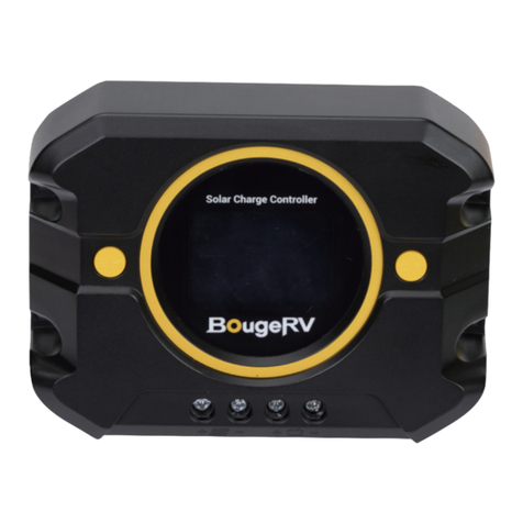
BougeRV Sunflow 60A User manual

NEGATIVE GROUND
MPPT SOLAR CHARGE CONTROLLER
www.bougerv.com


Content
1. Safety Instructions -----------------------------------------------------------1
2. Technical After Services----------------------------------------------------2
3. Identification Of Parts-----------------------------------------------------3
4. LCD Display Interface Overview------------------------------------------4
5. System Wiring----------------------------------------------------------------5
6. Wiring Instructions--------------------------------------------------------- 5
7. LCD Display Interface-------------------------------------------------------7
7-1. Menu Display Icon------------------------------------------------------------7
7-2. Key Operation-----------------------------------------------------------------7
8. Working Mode----------------------------------------------------------------9
8-1. Working Mode 1: Load mode-----------------------------------------------9
8-2. Working Mode 2: No load mode-----------------------------------------10
8-3. Working Mode 3: Viewing mode-----------------------------------------11
9. Bluetooth module-----------------------------------------------------------12
10. Parameter setting menu-------------------------------------------------13
Menu 1: Battery type setting(Mode 1, Mode 2)-----------------------------13
Menu 2: System voltage(Mode 1, Mode 2)-----------------------------------14
Menu 2.1: Boost charging voltage(Mode 1, Mode 2)-----------------------14
Menu 2.2: Floating charging voltage(Mode 1,Mode 2)--------------------15
Menu 2.3: Boost charging reconnect voltage(Mode 1,Mode 2)---------15
Menu 2.4: Equalizing charging voltage(Mode 1,Mode 2)-----------------15
Menu 2.5: Over-discharge voltage(Mode 1)---------------------------------15
Menu 2.6: Over-discharge delay(Mode 1)------------------------------------16
Menu 2.7: Over-discharge reconnect voltage(Mode 1)--------------------16
Menu 3: Solar panel output voltage(Mode 1,Mode 2,Mode 3)-----------16
Menu 4: Solar panel output current(Mode 1,Mode 2,Mode 3)----------17
Menu 5: Generated energy of the day(Mode 1,Mode 2,Mode 3---------17
Menu 6: Load current(Mode 1,Mode 3)---------------------------------------17
Menu 7: Discharge energy of the day (mode 1, mode 3)-----------------18
Menu 8: The controller temperature(mode 1, mode 2, mode 3)-------18
Menu 9: The battery temperature(mode 1, mode 2,mode 3)----------18

Menu 10: Load mode(mode 1)------------------------------------------------19
Menu 10.1: Light control mode + Duration mode(mode 1)--------------20
Menu 11: Lithium battery low temperature charging protection (mode
1, mode 2)--------------------------------------------------------------------------20
Menu 12: Load short circuit protection(mode 1)---------------------------21
Menu 13: Charging current(mode 1, mode 2)------------------------------21
Menu 14: Constant voltage output of lead acid battery(mode 1, mode
2)------------------------------------------------------------------------------------21
Menu 15: Light control voltage(mode 1)-----------------------------------22
Menu 16: Light control delay(mode 1)---------------------------------------22
Menu 17: Error code(mode 1, mode 2, mode 3)---------------------------22
11. System restart & Factory reset------------------------------------------23
Menu 18: System restart(mode 1, mode 2, mode 3)----------------------23
Menu 19: Factory reset(mode 1, mode 2, mode 3)------------------------23
12. Error Code-------------------------------------------------------------------24
13. Base Specification---------------------------------------------------------26
14. Battery Charge Parameter----------------------------------------------27
15. TTL communication-------------------------------------------------------29
16. RS485------------------------------------------------------------------------ 29
17. CAN communication(Optional)----------------------------------------29
18. Charging-------------------------------------------------------------------- 30
18-1. Charging of lead-acid battery-------------------------------------------30
18-2. Charging of lithium battery---------------------------------------------31
19. Product Dimensions------------------------------------------------------32

1. Safety Instructions
Please save these instructions
1.Read all of the instructions and cautions in the manual before
installation.
2.There are no repairable parts for this controller,do not disassemble
or attempt to repair the controller.
3.Keep the controller from the water.
4.Make sure all connections with controller are tight.
5.Please read the product installation steps to ensure all connections
are correct.
Please follow the safety instructions for operation, the damage caused
by not following the safety instructions shall be borne by the individual.
1-1.General Safety Information
1.NEVER connect the solar panel array to the controller without a
battery. The battery must be connected first.
2.Ensure input voltage does not exceed 100 Voc to prevent permanent
damage.
3.Ensure that the output current of the solar panel does not exceed
the rated charging current of the controller.
1-2.Charge Controller Safety
1 . Do not let the positive (+) and negative (-) terminals of the battery
touch each other.
2. Explosive battery gases may be present while charging. Be certain
there is enough ventilation to release the gases.
3. Be careful when working with large lead-acid batteries. Wear
goggles and have fresh water available in case there is contact with
the battery acid.
4. Over-charging and excessive gas precipitation may damage the
battery plates and activate material shedding on them. Too high of an
equalizing charge or too long of one may cause damage. Please
carefully review the specific requirements of the battery used in the
system.
1-3.Battery Safety
1

2. Technical After Services
BougeRV provides 1-on-1 Solar Solution.
If you have any questions during use, please feel free to contact us:
If you could provide the following relevant information to our email
([email protected]); we can provide you with technical
support solutions faster.
(1)The connection method of the solar panels (series/parallel,
quantity, voltage, power).
(2)The voltage and battery type of the battery.
(3)The pictures or videos of the controller: battery voltage, battery
charging current, the output voltage of the solar panel.
1-408-656-8402
www.bougerv.com
1-669-232-7427
Whataspp
2

3
3. Identification Of Parts
1
1
2
3
4
5
6
7
8
9
10
11
2
3
9 10 11
4 5 6 7 8
LCD Display Screen
Button
PV Positive Terminal
PV Negative Terminal
Battery Negative Terminal
Load Negative Terminal
Battery Positive Terminal
Load Positive Terminal
TTL Communication Interface
Temperature sensor Interface
RS485/CAN Communication Interface

4
1
2
3
4
5
6
7
8
9
10
11
12
13
14
15
16
17
Daytime icon
Night icon
Solar panel
Battery
Load
Charging state
Discharging state
System voltage
RS485/CAN communication icon
Bluetooth icon
Battery type
Charging stage
Load light control icon
Parameter
Unit symbol
Operating mode
Warning icon
4. LCD Display Interface Overview
11 9
8
17
16
2
12
13
1
3 6 4 7 5
14 15 10
16 9
81

5
1. The positive and negative poles of the battery must be connected
to the battery terminals of the controller first.
2. Finally, connect the positive and negative poles of the solar panel to
the PV terminals of the controller.
3.Make sure that the Bluetooth of the mobile phone is turned on, and
open the APP "Solar" to enter the setting interface.
5.System Wiring
6.Wiring Instructions
1.Remove the plastic cover.(Pick up) 2.Unscrew the screws.
(Counterclockwise)
1 2

6
5. Check the wiring condition
and put the plastic cover back.
Please strictly follow the above
sequence for connection.
Note:
During the wiring process, the
attached terminal lugs can be
used for connection. After
stripping the wire, put it into the
terminal lugs and squeeze it with
a crimping pliers.
3
5
4
3. Plug the cable into the
correct port.
4. Tighten the screws.
(Clockwise)
fuse s

7
7. LCD Display Interface
Press the button to scroll the menu backward to the
previous menu.
Press the button to scroll the menu forward to the
next menu.
Indicate And Warning
BAT Type
Display Section
Charge And Load Status
Parameter
Status
System Error
Indication
Voltage
Indication
On
OFF
12V
24V
12V System Voltage
24V System Voltage
System Error - Check Error Code
System Normally
Status Icon Indication Status Description
Day Night
And Charge
Indication
Battery
Indication
Load
Indication
On
On
On
Daylight Detected
No Daylight Detected
Solar Charging Battery
Battery Voltage is Hight
Battery Voltage is Middle
Battery Voltage is Low
Load On
Load Off
7-1.Menu Display Icon
7-2.Key Operation
1. Menu Switching
1. Safety Instructions -----------------------------------------------------------1
2. Technical After Services----------------------------------------------------2
3. Identification Of Parts-----------------------------------------------------3
4. LCD Display Interface Overview------------------------------------------4
5. System Wiring----------------------------------------------------------------5
6. Wiring Instructions--------------------------------------------------------- 5
7. LCD Display Interface-------------------------------------------------------7
7-1. Menu Display Icon------------------------------------------------------------7
7-2. Key Operation-----------------------------------------------------------------7
8. Working Mode----------------------------------------------------------------9
8-1. Working Mode 1: Load mode-----------------------------------------------9
8-2. Working Mode 2: No load mode-----------------------------------------10
8-3. Working Mode 3: Viewing mode-----------------------------------------11
9. Bluetooth module-----------------------------------------------------------12
10. Parameter setting menu-------------------------------------------------13
Menu 1: Battery type setting(Mode 1, Mode 2)-----------------------------13
Menu 2: System voltage(Mode 1, Mode 2)-----------------------------------14
Menu 2.1: Boost charging voltage(Mode 1, Mode 2)-----------------------14
Menu 2.2: Floating charging voltage(Mode 1,Mode 2)--------------------15
Menu 2.3: Boost charging reconnect voltage(Mode 1,Mode 2)---------15
Menu 2.4: Equalizing charging voltage(Mode 1,Mode 2)-----------------15
Menu 2.5: Over-discharge voltage(Mode 1)---------------------------------15
Menu 2.6: Over-discharge delay(Mode 1)------------------------------------16
Menu 2.7: Over-discharge reconnect voltage(Mode 1)--------------------16
Menu 3: Solar panel output voltage(Mode 1,Mode 2,Mode 3)-----------16
Menu 4: Solar panel output current(Mode 1,Mode 2,Mode 3)----------17
Menu 5: Generated energy of the day(Mode 1,Mode 2,Mode 3---------17
Menu 6: Load current(Mode 1,Mode 3)---------------------------------------17
Menu 7: Discharge energy of the day (mode 1, mode 3)-----------------18
Menu 8: The controller temperature(mode 1, mode 2, mode 3)-------18
Menu 9: The battery temperature(mode 1, mode 2,mode 3)----------18

8
In the menu interface, press and hold the button for 2s to
enter the menu parameter adjustment interface.
2. Enter the Parameter Setting Interface
Enter the parameter setting interface, press the button to
adjust the parameter.(Decrease)
Enter the parameter setting interface, click the button to
adjust the parameter.(Add)
3. Adjust Parameters
Enter the parameter setting interface, press the button to
adjust the parameter.(Decrease)
Enter the parameter setting interface, click the button to
adjust the parameter.(Add)
After adjusting the parameters, press and hold the button
for 2s to confirm the setting parameters.
After adjusting the parameters, press and hold the button
for 2s to confirm the setting parameters.
4. Save Parameters
On the main menu interface, press and hold the button
for 5s to enter the working mode setting interface, and the
working mode icon will display.
5.2 Adjust working mode
5.3 Save working mode setting
5. Working mode setting
5.1 Enter the working mode setting interface

9
Charging Stage Menu
16 9
81
16 9
81
16 9
81
16 9
81
Menu 2.1:
Boost charging voltage
Menu 2.3:
Boost charging
reconnect voltage
Menu 2.4:
Equalizing charging
voltage
Menu 2.5:
Over-discharge voltage
16 9
81
Menu 2.6:
Over-discharge delay
Menu 2.7:
Over-discharge r
econnect voltage
Menu 2.2:
Floating charging voltage
16 9
81
16 9
81
16 9
81
Menu 4:
Solar panel output current
16 9
81
Menu 5:
Generated energy of the day
16 9
81
Menu 6:
Load current
16 9
81
Menu 7:
Discharge energy of the day
16 9
81
Menu 8:
The controller temperature
16 9
81
Menu 9:
The battery temperature
Menu 10:
Load mode
16 9
81
Menu 10.1:
Light control mode +
Duration mode
16 9
81
Menu 11:
Lithium battery low
temperature charging protection
16 9
81
Menu 12:
Load short circuit protection
16 9
81
Menu 13:
Charging current
16 9
81
8-1 Working Mode 1: Load mode
8. Working Mode
16 9
81
Menu 2:
System voltage
16 9
81
Menu 3:
Solar panel output voltage
Menu 1:
Battery type setting
16 9
81

10
8-2 Working Mode 2: No load mode
16 9
81
16 9
81
16 9
81
16 9
81
16 9
81
Menu 1:
Battery type setting
Menu 3:
Solar panel output voltage
Menu 4:
Solar panel output current Menu 5:
Generated energy of the day Menu 8:
The controller temperature
Menu 9:
The battery temperature
Menu 13:
Charging current
Menu 17:
Error code
Menu 14:
Constant voltage output of
lead acid battery
Menu 11:
Lithium battery low
temperature charging protection
16 9
81
16 9
81
16 9
81
16 9
81
16 9
81
16 9
81
Menu 15:
Light control voltage
16 9
81
Menu 16:
Light control delay
Menu 14:
Constant voltage
output of lead acid battery
16 9
81
Menu 17:
Error code
16 9
81
16 9
81
Menu 2:
System voltage

11
It is recommended to switch to mode 3 after setting the
system parameters, so that it is convenient to check the
daily work of the PV system.
8-3 Working Mode 3: Viewing mode
16 9
81
Menu 2.1:
Boost charging voltage
16 9
81
Menu 2.4:
Equalizing charging
voltage
Menu 2.2:
Floating charging voltage
16 9
81
Menu 2.3:
Boost charging
reconnect voltage
16 9
81
16 9
81
Menu 3:
Solar panel output voltage
16 9
81
Menu 4:
Solar panel output current
16 9
81
Menu 5:
Generated energy of the day
16 9
81
Menu 6:
Load current
16 9
81
Menu 7:
Discharge energy of the day
16 9
81
Menu 8:
The controller temperature
16 9
81
Menu 9:
The battery temperature
Menu 17:
Error code
16 9
81
16 9
81
Menu 2: System voltage

12
9. Bluetooth module
Built-in Bluetooth communication function can monitor the
operation data, fault status and adjust the operation parameters of
the controller in real time through mobile APP.
Scan the QR code to download the application;
Search for "Solar App" in the APP Store (for IOS devices) or Google
Play (for Android devices).
Download
IOS & Android
Solar APP

13
10. Parameter setting menu
Main menu (current)
①SLD =Sealed lead acid battery
②GEL=GEL battery
③FLD=Flooded lead acid battery
④LI=Lithium iron phosphate battery/LiFePO4
⑤USE=Custom battery
Setting method:
1. On the battery type menu, press and hold [SELECT] for more than 2s
until the parameter flashes to enter the battery type parameter setting
interface.
2. On the battery type parameter setting interface, single press
[SELECT] or [ENTER] to adjust the parameters.
3. After completing the parameter setting, press and hold [ENTER] for
more than 2s until the parameter does not flash, and the parameter
setting saves successfully; single press [ENTER] to switch to the next
menu or automatically jump back to the main menu after 10s of no
operation.
1.On the parameter setting interface, if there is no operation for 10s, it
will automatically jump back to the main menu.
2.On the parameter setting interface, if the parameter is not confirmed,
the parameter will keep flashing, confirm until the parameter does not
flash, indicating that the parameter setting is successful.
3.The backlight turns off after 10s of no operation.
Main Menu
Menu 1: Battery type setting (Mode 1, Mode 2)
Main menu (voltage)
Automatic loop
playback every 5s
16 9
81
16 9
81
16 9
81

14
Setting method:
1. On the system voltage menu, press and hold [SELECT] for more
than 2s until the parameter flashes to enter the system voltage
parameter setting interface.
2. On the system voltage parameter setting interface, single press
[SELECT] or [ENTER] to adjust the parameters.
3. After completing the parameter setting, press and hold [ENTER] for
more than 2s until the parameter does not flash, and the parameter
setting saves successfully; single press [ENTER] to switch to the next
menu or automatically jump back to the main menu after 10s of no
operation.
Note: The system voltage will take effect after the system voltage
setting saves successfully.
1. Automatically identify voltage
(only applicable to the lead-acid battery)
2. 12V
3. 24V
①12V system:
9-17V, 0.1V step (default 14.4V)
②24V system:
18-34V, 0.2V step (default 28.8V)
Note:
This menu will only appear when the battery type is set to LI or USE.
Setting method:
1. On the boost charging voltage menu, press and hold [SELECT] for
more than 2s until the parameter flashes to enter the boost charging
voltage parameter setting interface.
2. On the boost charging voltage parameter setting interface, single
press [SELECT] or [ENTER] to adjust the parameters.
3. After completing the parameter setting, press and hold [ENTER] for
more than 2s until the parameter does not flash, and the parameter
setting is successful; single press [ENTER] to switch to the next menu
or automatically jump back to the main menu after 10s of no operation.
Menu 2: System voltage(Mode 1, Mode 2)
Menu 2.1: Boost charging voltage(Mode 1, Mode 2)
16 9
81
16 9
81

15
Menu 2.3: Boost charging reconnect voltage
(Mode 1, Mode 2)
Note:
This menu will only appear when the battery type is set to LI or USE.
Setting method: Same as above.
①12V system:
9-17V, 0.1V step (default 13.2V)
②24V system:
18-34V, 0.2V step (default 26.4V)
16 9
81
Menu 2.4: Equalizing charging voltage(Mode 1, Mode 2)
Note:
This menu will only appear when the battery type is set to USE.
Setting method: Same as above.
①12V system:
9-17V, 0.1V step (default 14.6V)
②24V system:
18-34V, 0.2V step (default 29.2V)
16 9
81
Menu 2.5: Over-discharge voltage(Mode 1)
Note:
This menu will only appear when the battery type is set to LI or USE.
Setting method: Same as above.
①12V system:
9-17V, 0.1V step (default 11.1V)
②24V system:
18-34V, 0.2V step (default 22.2V)
16 9
81
Menu 2.2: Floating charging voltage(Mode 1, Mode 2)
Note:
This menu will only appear when the battery type is set to USE.
Setting method: Same as above.
16 9
81
①12V system:
9-17V, 0.1V step (default 13.8V)
②24V system:
18-34V, 0.2V step (default 27.6V)

16
Note:
This menu will only appear when the battery
type is set to USE.
Setting method: Same as above.
1-60s. (default 5s)
Display solar panel output voltage.
Note:
The voltage value only can be read, but
cannot be adjusted;
Setting method: Same as above.
①12V system:
9-17V, 0.1V step (default 12.6V)
②24V system:
18-34V, 0.2V step (default 25.2V)
Note:
This menu will only appear when the battery type is set to LI or USE.
Setting method: Same as above.
Menu 2.6: Over-discharge delay(Mode 1)
Menu 2.7: Over-discharge reconnect voltage(Mode 1)
Menu 3: Solar panel output voltage
(Mode 1, Mode 2, Mode 3)
16 9
81
16 9
81
16 9
81
This manual suits for next models
2
Table of contents
Other BougeRV Controllers manuals
Popular Controllers manuals by other brands
Specified Controls
Specified Controls SC-LLC-200 installation instructions
Controls
Controls MVP-316 product manual
Osram
Osram DALIeco operating instructions
Resol
Resol DeltaSol C/3 Mounting, Connection, Operation, Troubleshooting, Examples
IKUSI
IKUSI SPI-300 Setup guide
Marshall Amplification
Marshall Amplification CV-RCP-V2 quick start guide
