Boumatic Opti-Flo II User manual

Opti-FloII Upgrade Kit 1 9E-832
Instructional Content and Purpose
These instructions aim to aid those responsible (outlined under
“Responsibilities”)forinstalling,operating,maintaining,troubleshooting,
and servicing this product.
Responsibilities
Procedures in these instructions are to be performed according to
applicable codes (state, local, and other) by the person(s) qualified
(licensed, if applicable) to do so—that is
• welding must be done by a qualified welder.
• high-voltage AC power wiring must be done by a qualified (licensed)
electrician in compliance with the latest edition of the ANSI/NFPA
Standard 70, National Electrical Code, and in compliance with the
local wiring codes as applicable.
• other installation, major maintenance, and service work must be
done by the dealer.
• product/system checkout and troubleshooting steps are to be
performed by the dealer or technician.
• deviation from these installation instructions could affect product
performance or create a hazardous situation. Under no
circumstances will Bou-Matic be responsible for any problems
causedinwholeorinpartbyanydeviationfrominstallationprocedures
specified in these instructions without prior written approval from
Bou-Matic.
• operation steps may be performed by the owner/operator once the
dealer or technician has successfully finished the product/system
checkout. The owner/operator is responsible for properly operating,
maintaining, and monitoring the product/system to ensure that it
works properly.
Closecompliancewiththeprocedureshereinisessentialfortheowner
to get maximum benefit from the product/system.
Disclaimers
No warranties are contained in these instructions. The division of
responsibilities,statedabove,isageneralreminderofthoseprovisions
in the applicable dealer contract and does not change any agreement
betweenBou-Maticandthedealer. Informationinthispacketisnotall-
inclusive and cannot cover all unique situations.
____________________________________________________________________________________
Opti-Flo II™ Upgrade Kit
InstallationInstructions
Introduction
Bou-Matic® part number 4024556 is a kit designed to
replace the ABB ACS 300, 230 Volt control with the
Magnetek GPD 315, 230 Volt control. The Magnetek
GPD 315 control provides the same features as the ABB
ACS300control.Whenproperlyinstalledandprogrammed
the Opti-Flo II™ with a Magnetek GPD 315 control will
operate the same as the Opti-Flo II with an ABB ACS
300control.
1.
Preparation
1.1 Verifying Part and Tool Requirements
The kit contains the following:
1. Magnetek GPD 315 control assy. ............................. 1
2. Wiring label ............................................................... 1
3. Screwdriver with small blade ................................... 1
4. Magnatek GPD 315 Instruction Manual ................... 1
When installing parts, the dealer should be equipped with
standardinstallation tools. Nonstandard toolswill be noted
where used.
1.2 Reviewing Personal Safety Messages
Follow the safety messages listed below and throughout
the packet to prevent possible bodily injury:
—WARNING——————————————————–
Before opening control box disconnect power from electrical
supply or severe injury or death could occur.
—WARNING——————————————————–
Dangerous voltage. Consult Magnetek users manual before
opening the Magnetek controller. Wait at least 5 minutes after
disconnecting supply before removing the cover. High leakage
current. Earthconnectionessentialbefore connecting supply.
Contents
Introduction .......................................................................... 1
1. Preparation ..................................................................... 1
1.1 Verifying Part and Tool Requirements.................... 1
1.2 Reviewing Personal Safety Messages ................... 1
2. Installation....................................................................... 1
3. Verifying Proper Operation............................................. 3
4. GPD 315 Parameters ...................................................... 8
Bou-MaticLLC
1919S.StoughtonRd.
P.O.Box8050
Madison,WI 53708-8050
(608)222-3484Fax:(608)222-9314
Internet:www.Bou-Matic.com

Opti-FloII Upgrade Kit 2 93-832
2. Installation
1. Disconnect power from the electrical supply.
2. Open the Opti-Flo II enclosure.
3. RemovetheplasticcoveroftheABBACS300control
by loosening the 2 screws at the bottom of the cover
andsqueezingthe2plastictabslocatedatthetopside
of the cover.
— NOTE ————————————————––––––––––––
Do not cut the wires going to the ABB ACS 300 control.
4. Remove ONLY the wires from the terminal blocks of
the ABB ACS 300 control.
5. Remove the solid color brown, red and orange wires
from the Opti-Flo II main terminal block which come
from the input filter. Discard the filter.
6. Take the ABB ACS 300 control out of the enclosure
by removing and saving the 4 mounting screws and
lockingwashers.
—WARNING——————————————————–
Before opening control box disconnect power from electrical
supply or severe injury or death could occur.
—WARNING——————————————————–
Dangerous voltage. Consult Magnetek users manual before
opening the Magnetek controller. Wait at least 5 minutes after
disconnecting supply before removing the cover. High leakage
current. Earth connection essential before connecting supply.
7. InstalltheMagnetekGPD315assemblyintotheOpti-
FloIIenclosureusingthe4savedscrewsandlocking
washers(seeFigure2).
8. Connect thegreenwirewiththeyellowstripe(Ground)
fromtheMainterminalblocktotheGroundscrewofthe
MagnetekGPD315.TheGroundscrewislocatedjust
belowthe T3 terminalblockposition of theMagnetek
GPD315(seeFigure 1).
gniriWretliFtuptuO:1elbaT
htiweriwetihW epirtsnworb
lanimretoT fo1Tnoitacol 513DPG 1erugiFeeS
htiweriwetihW epirtsder
lanimretoT fo2Tnoitacol 513DPG 1erugiFeeS
htiweriwetihW epirtsegnaro
lanimretoT fo3Tnoitacol 513DPG 1erugiFeeS
9. Crimp the two white wires with the yellow stripe from
the existing wire harness into the wire adapter of the
samecolor (see Figure 1).
10. Crimpthetworedwireswiththeyellowstripefromthe
existingwireharnessintothewireadapterofthesame
color(seeFigure 1).
11. Usingthenewwiringlabelasaguideinstallthe3wires
from the ORIGINAL output filter, white wires with the
brown, red and orange stripes to the proper terminal
locations of the Magnetek GPD 315 (see Figure 1,2
andTable1).
— IMPORTANT ——————————————––––––––––
Miswiring will cause damage to the Magnetek GPD 315.
snoitcennoCssenraHeriW:3elbaT
eriweulB yaleroT 01noitacol,1K 1erugiFeeS
yargelbuodtrohS seriw yaleroT 9noitacol,1K 1erugiFeeS
yargelbuodgnoL seriw
ehtfo7JoT niamIIolF-itpO kcolblanimret 1erugiFeeS
dnaetihwelbuoD seriwyarg
ehtfo6JoT niamIIolF-itpO kcolblanimret 1erugiFeeS
htiwetihwelbuoD seriwepirtsegnaro
ehtfo2JoT niamIIolF-itpO kcolblanimret 1erugiFeeS
etihwdnaetihW epirtsteloivhtiw seriw
ehtfo4JoT niamIIolF-itpO kcolblanimret 1erugiFeeS
htiwetihwelbuoD seriwepirtsteloiv yaleroT 5noitacol,1K 1erugiFeeS
wolleyhtiwetihW eriwepirts yaleroT 2noitacol,1K 1erugiFeeS
gniriWretliFtupnI:2elbaT
eriwnworB noitacollanimretoT IIolF-itpOehtfo1L kcolblanimretniam 1erugiFeeS
eriwdeR noitacollanimretoT IIolF-itpOehtfo2L kcolblanimretniam 1erugiFeeS
eriwegnarO noitacollanimretoT IIolF-itpOehtfo3L kcolblanimretniam 1erugiFeeS

Opti-FloII Upgrade Kit 3 9E-832
13. Usingthenewwiringlabelasaguide,connectthesolid
brown,redandorangewiresfromtheinputfiltertothe
properterminalblocklocationsoftheOpti-FloIImain
terminal block (see Figures 1,2 and Table 2).
12. Usingthenewwiringlabelasaguide,removeexisting
wires from the Opti-Flo II main terminal block and
install the proper wire from the new wire harness
coming from the GPD 315 (see Table 3). The wire
colorsbetweenthenewandexistingwireharnessare
essentiallythesametohelptheinstallationandeliminate
confusion. Theoldwireharnessistobediscarded(see
Figure1).
14. Atthispointallwiringshouldbecompleted.Insureall
wiresaresecurelyinstalled.Usingthenewwiringlabel,
doublechecktoverifythatallwiresareinstalledatthe
properlocations(seeFigure2).
— IMPORTANT ——————————————––––––––––
Miswiring will cause damage to the Magnetek GPD 315.
3. Verifying Proper Operation
1. Refer to Figure 3 for a function block diagram.
2. VerifythatallReceiverProbesareintheOFFposition
and that there is an OPEN between Receiver Probe
COMMON ( J3 ) and the LOW, MEDIUM, and HIGH
Receiver probe inputs ( J5, J6, and J7 ).
3. Switch“ON”powerfrom the breaker tothe
Opti-Flo II.
4. Thecontrolshouldcomeupwiththegreen“RUN”LED
flashing,thegreen“FOUT”LEDONcontinuously,the
red4digitdisplayshowing“0.00” andthered“ALARM”
LEDOFF.
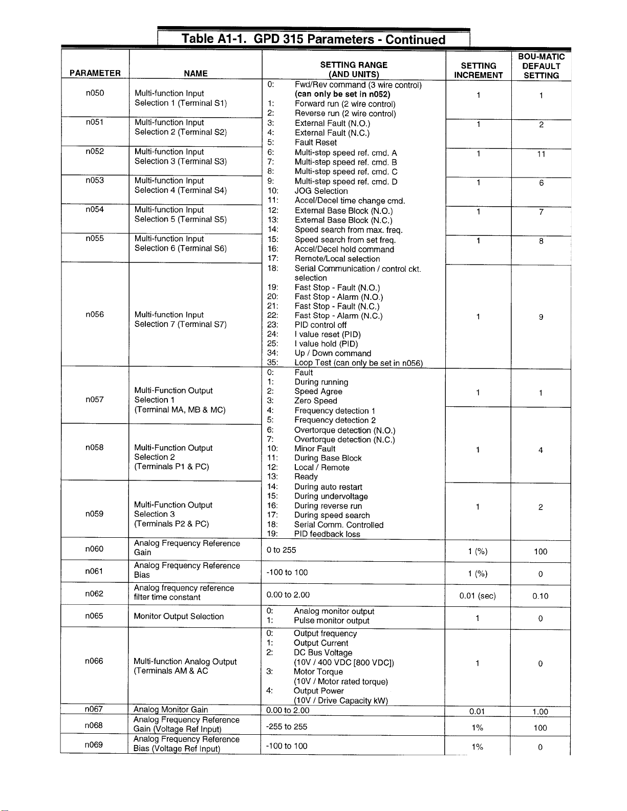
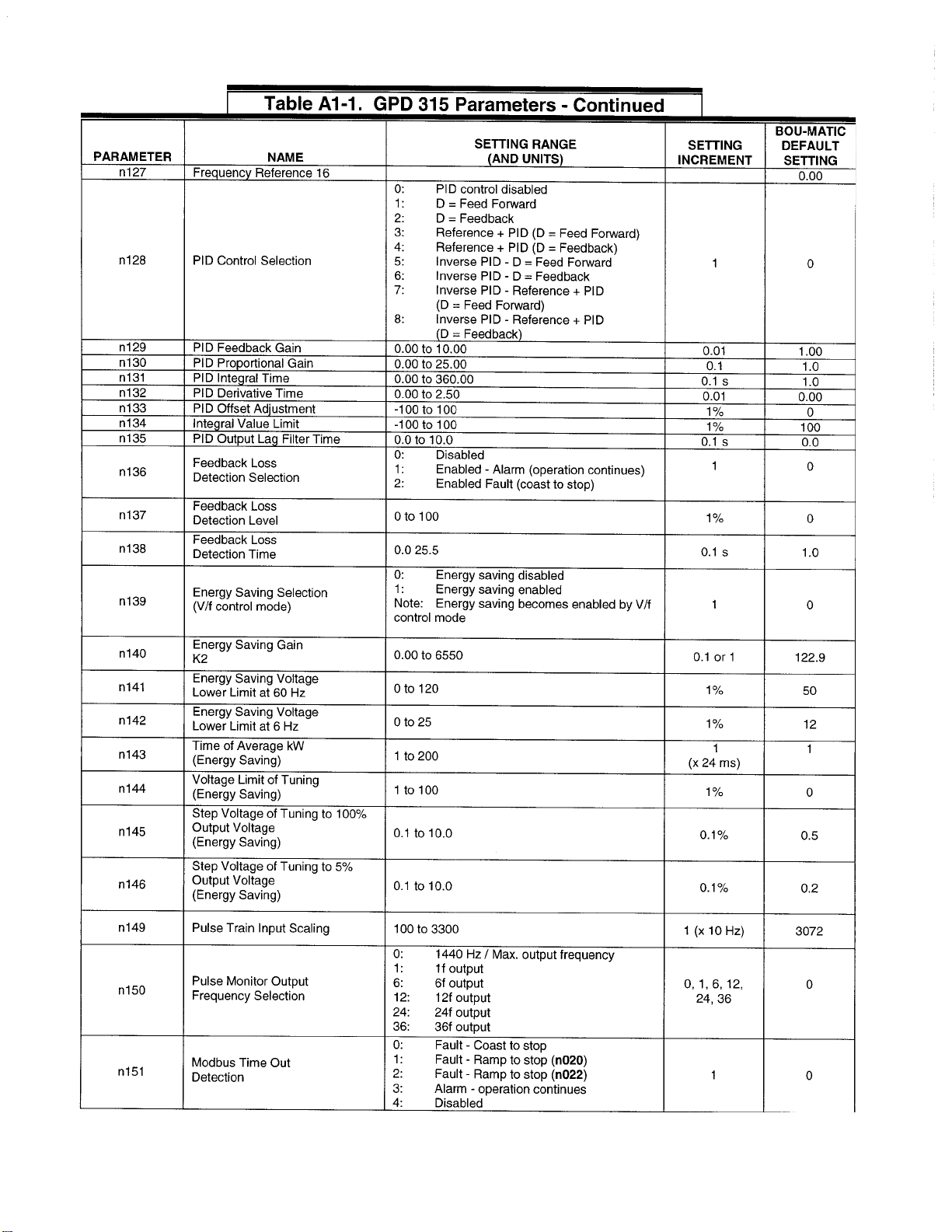
5. The Magnatek GPD 315 parameters can be viewed
and programmed by using the Digital Operator (see
Figure1).Pressthe“DSPL”keyuntilthegreen“PRGM”
LED turns ON. Each parameter starts with the small
letter “n” and is followed by a 3 digit number. The red
4 digit display will display “nXXX” where XXX is a
numberbetween001and179.Usethe“^”(UP)keyto
incrementupandthe (DOWN)keytoincrementdown
dependingonwhich parameter you are interestedin.
Once you get to the desired parameter press the
“DATA/ENTER” key to display the present value
programmedintotheparameter.Tochangeorprogram
thedesiredparameterusethe“^”(UP)keytoincrement
upandthe (DOWN)keytoincrementdowndepending
onwhatvalueyouwanttoprogramintothatparameter.
Once the desired value is being displayed press the
“DATA/ENTER”keytostorethedesiredvalueintothe
parameter.Afterallparameterprogrammingiscomplete
pressthe“DSPL”keyuntilthegreen“FOUT”LEDturns
ON. A listing of installation specific parameters is
givenin Table 4. A completelistofall the parameters
can be found in Table A1-1.
—NOTE——————————————–––––––––––––––––
The parameters listed in Table 4 are the ONLY ones that may
need to be reprogrammed for proper operation. Of these,
Parametern036,“MotorRatedCurrent”isthesetfora1HpBou-
Matic milk pump motor and MUST be reprogrammed per the
motor nameplate to insure proper operation.
6. Activatethemanualpumpoutswitch.Themilkpump
motorshouldstartrunning. Verifythat the milk pump
isrotatinginthecorrectdirection. Ifitisnot,turn“OFF”
the breaker and check the wiring of the motor.
7. Aftercheckingmotordirection,checkthefloatswitches
forproperoperation.Thelowfloatshouldrunthemotor
at50Hz. Thehighfloatshouldrunthemotorat60Hz.
If an optional middle float switch is used, it will be
preset to run at 55 Hz. Check each float individually.
8. Check the Milk/Wash switch for proper operation. All
floatswitchesshouldbeloweredandthemotorshould
gnimmargorP513DPG:4elbaT
retemaraP foemaN noitcnuF tnemmoC citaM-uoB tluafeD
110n mumixaM ycneuqerF
rePteS rotoM etalpemaN zH06
210n mumixaM egatloV
rePteS rotoM etalpemaN stloV032
120n noitareleccA 2emiT
=,#rehgiH emitregnol tnioptesot .ceS4
220n noitareleceD 2emiT
=,#rehgiH emitregnol tnioptesot .ceS01
420n ycneuqerF 1ecnerefeR
ycneuqerF WOLrof EBORP zH05
520n ycneuqerF 2ecnerefeR
ycneuqerF MUIDEMrof EBORP ZH55
720n ycneuqerF 4ecnerefeR
ycneuqerF HGIHrof EBORP zH06
630n detaRrotoM tnerruC
rePteS rotoM etalpemaN spmA8.2

Opti-FloII Upgrade Kit 4 93-832
1
notberunning. SwitchtheMilk/WashswitchtotheWash
positionand raisethelowfloat. Themotorshouldrun up
to60Hzinjustafewseconds. Lowerthefloatswitchand
the motor should stop turning in just a few seconds.
9. Adjusttheparametersas required. All parameter defaults
are set for a 1 Hp motor. If a 2 Hp or 3 Hp motor is used,
someparametersmustbechanged.Alistingofinstallation
specific parameters is given in Table 4. A complete
parameter list is given in Table A1-1.
10. If the individual components of the system seem to be
operating correctly, run a wash cycle to check out the
completesystem.Duringthewashcycle,switchtheMilk/
WashmodebetweenMilkandWashmodes. IntheWash
modethecontroltriestorunthemilkpumpat60Hzaslong
as the low float switch is closed.
Thepumpwillslowdownquicklywhenthelowfloatswitch
opens. In the Milk mode the control tries to run the milk
pumpat50Hzwhenthelowfloatswitchisclosed,andwill
ramp up to 60 Hz only when the high float switch closes.
Itwill ramp slowly downfrom60 Hz onlywhenthe
high float switch opens. It will ramp slowly down
from the 50 Hz when the low float switch opens. If
the control is connected to a solenoid to control
waterflowtoaplatecooler,thesolenoidshouldbe
“OFF”whenthecontrolisintheWashmodeandthe
solenoid shouldbe“ON”whenthecontrolisinthe
Milk mode, with the milk pump running.
11. Replacetheexistingwiringlabelwiththewiringlabel
provided in the kit.
12. Mountthe plastic shroud backontothe Magnetek
GPD 315.
13. Mount the access panel back onto the Magnetek
GPD315.
14. Close and tighten the Opti-Flo II cover.

Opti-FloII Upgrade Kit 5 9E-832
2
1. Wiring the GPD 315 to the Opti-Flo II main terminal block 832_1
GPD 315
Opti-Flo II main terminal block
Digitaloperator

Opti-FloII Upgrade Kit 6 93-832
2. Opti-Flo II upgrade kit wiring label, P/N 4024550 832_2

Opti-FloII Upgrade Kit 7 9E-832
6
3. Wiring label, function block diagram, P/N 4024550 832_3

Opti-FloII Upgrade Kit 8 93-832
4. GPD 315 Parameters

Opti-FloII Upgrade Kit 9 9E-832
Opti-FloII Upgrade Kit 10 93-832

Opti-FloII Upgrade Kit 11 9E-832

Opti-FloII Upgrade Kit 12 93-832
Opti-FloII Upgrade Kit 13 9E-832
Table of contents
Popular Control Unit manuals by other brands


socomec
socomec DIRIS O-m quick start

Honeywell
Honeywell Braukmann FD300 installation instructions

HP
HP 81541MM Operating and programming manual

Niobrara
Niobrara QUCM 3964 Installation and programming manual

GESTRA
GESTRA QuickEM Original Installation Instructions

Watts
Watts WFC-03 HCM RF 230 Quick installation guide