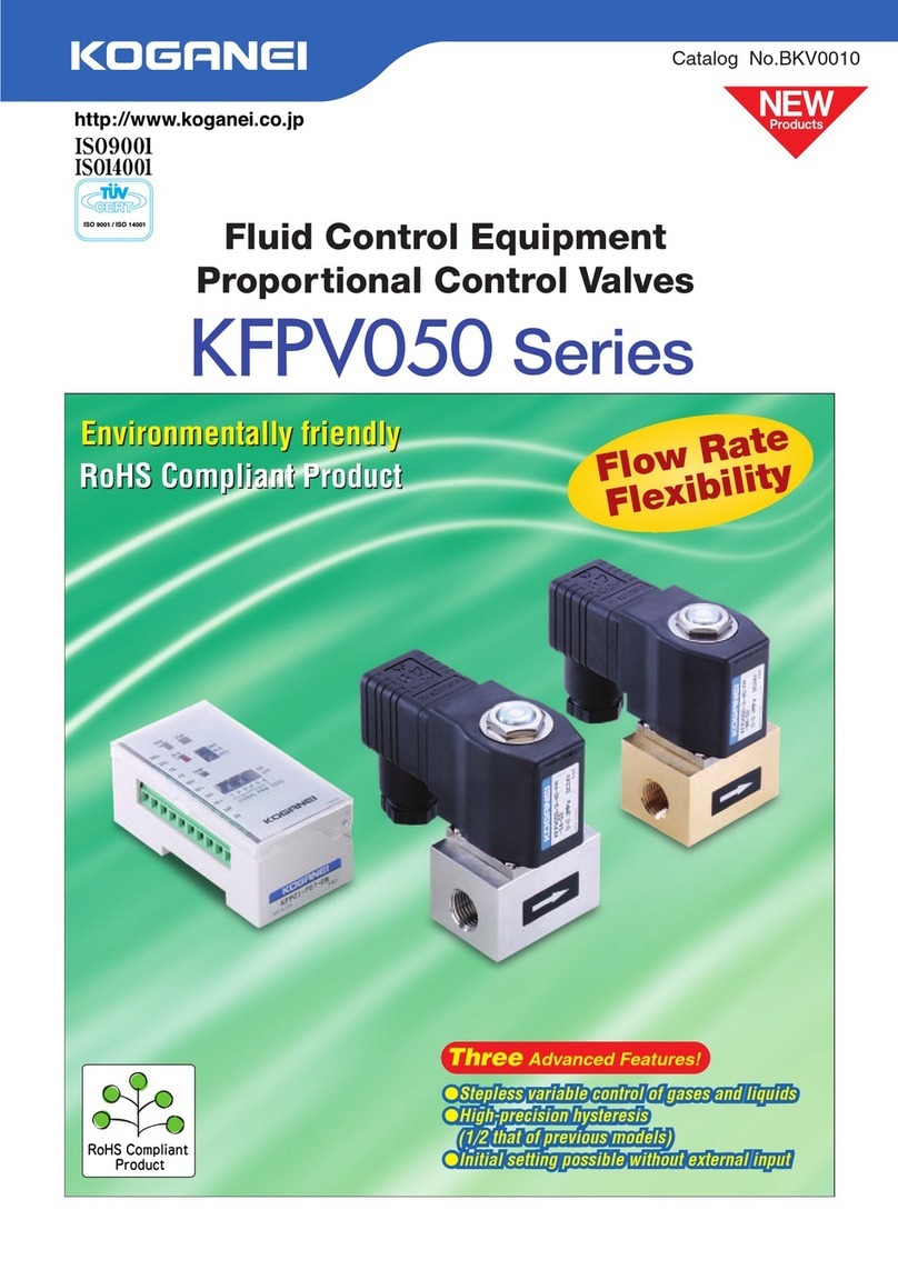
Koganei KFPV050 Series User manual

Catalog No.BK-V0016
Fluid Control Equipment
Proportional Control Valve
Three Advanced Features!
●Stepless variable control of gases and liquids
●High-precision hysteresis (1/2 that of previous models)
●Initial setting possible without external input
●Stepless variable control of gases and liquids
●High-precision hysteresis (1/2 that of previous models)
●Initial setting possible without external input
Three Advanced Features!
Gas, liquid
media adjusters
Koganei brand
All products are RoHS
directive compliant
Koganei brand
All products are RoHS
directive compliant
Large proportional
control valve lineup!
Large proportional
control valve lineup!
Large proportional
control valve lineup!
KFPV050•KFPV300 Series
032016

Read the safety precautions on page ❸before using this product.
CAUTION
Rc1/4 Direct Acting 2-port Valve,
Plunger type
Air flow rate control
that is approximately
6 timesNote greater
than that of the
KFPV050 series.
Note:
Under Koganei measurement
conditions.
Rc3/8, Rc1/2Note Direct Acting 2-port Valve, Plunger type
Note: Piping connection port diameter depends on orifice diameter.
In combination with a special controller, input signal size can be changed, which enables seamless
flow rate adjustment and highly accurate control of air, liquids, and other types of media.
Environmentally friendly RoHS compliant product!
Fluid Control Equipment
(Body material: Brass)
(Body material: SUS304)
(Body material: SCS13 (SUS304 equivalent))
In combination with the KFPC1 controller, it provides the following high-level specifications
(under Koganei test conditions): repeatability 2% F.S. or less, response accuracy: 2% F.S. or
less, low hysteresis: 5%F.S. or less.
NEW
Proportional Control Valves
KFPV300 Series
Proportional Control Valves
KFPV300 Series
Proportional Control Valves
KFPV050 Series
Proportional Control Valves
KFPV050 Series
Large
flow rate!
●
Enabling a seamless control of gas and liquid flow rates, it is a single unit with dual functions.
●High accuracy, high quality, and high response.
●
Enabling a seamless control of gas and liquid flow rates, it is a single unit with dual functions.
●High accuracy, high quality, and high response.
■Adjustable wiring
Greater freedom in wiring and design makes it easier to respond to equipment and device mounting conditions.
●Solenoid direction
can also be
changed.
●Wiring lead-out can be
up, down, left, or right in
90increments.
KFPV050 series KFPV050 series KFPV300 series
KFPV300 series
90°90°
360°360°
360°
90°
increments
●❶
Proportional Control Valves KFPV050•KFPV300 Series
032016

Safety precautions
…………………………
Handling instructions and precautions
……
Proportional control valve KFPV050 series
Display symbols and specifications
……
Inner construction diagrams, major parts
and materials, order codes
…………………
Dimensions …………………………………
Proportional control valve KFPV300 series
Display symbols and specifications
……
Inner construction diagrams, major parts
and materials, precaution symbols
…………
Dimensions …………………………………
Proportional control valve controller KFPC1
Specifications, nomenclature and functions,
order codes
…………………………………
Dimensions …………………………………
Flow rate conversion graphs ……………
Glossary ……………………………………
Introduction to related catalogs
…………
INDEX
No polarity
Valve driver current outputNote
Note: For information about valve driver current values (reference values), refer to the instruction manual
that comes with the controller.
To frame ground
4 to 20 mA or 0 to 10 V
SOL
SOL
FG
FG
SV+
SV−
IN+
IN−
24V
0V
+
−
+
−
+
−
Pressure gauge, etc.
(mV)
PID controller, etc.
24 VDC
Power
Solenoid
Solenoid
FG
FG
Monitor voltage +
Monitor voltage −
Input signal +
Input signal −
Power supply +
Power supply −
Proportional
control valve
KFPV050
series
Proportional
control valve
controller KFPC1
Proportional control valve controller KFPC1
Example of use
Example connection circuit configuration
●Water flow rate control
The KFPV050 series and KFPV300 series allows seamless control of the flow
rate in accordance with changes in the input signal size.
Now a single control valve can perform multiple-level flow control that normally
requires multiple ON/OFF type solenoid valves.
●2-liquid mixture
Mixes liquids A & B at a constant rate.
●Other
•Cylinder speed control
•Auto adjustment of ionizer air
flow rate in accordance with
workpiece type and size.
■With a circuit that supports default settings!
Initialization can be performed without external input.
■Highly reliable controller
●Reference input signal 4 to 20 mA, 0 to 10V.
●In order to mitigate wide fluctuations of the reference
input signal, the ramp response time can be adjusted
within a range of 0 to 10 seconds.
●Monitor signal for display of settings
and solenoid flow rate values.
●Zero point switch off function
completely seals the valve.
●Built-in temperature
compensation circuit.
●Two potentiometers set valve
opening points and fully open
flow rate values to match usage
conditions.
●LED monitor.
Proportional control valve controller KFPC1
●❷
●
●
●
●
●
●
●
●
●
●
●
●
●
❸
❺
❼
❽
❾
032016

Safety precautions (proportional control valves)
Before selecting and using the products, please read all the safety precautions carefully to ensure proper product use.
The safety precautions described below are to help you use the product safely and correctly, and to prevent injury or damage to you,
other people, and assets.
Always adhere to the following safety regulations: ISO4414 (Pneumatic fluid power - General rules and safety requirements for systems
and their components) and JIS B 8370 (Pneumatic system regulations).
●Do not use the product in excess of its specification range.
Doing so creates the risk of product breakdown, erratic
operation, or damage.
●The media that can be used is air, neutral gas, water, and gases
and fluids that do not affect component parts. Media other than
those above creates the risk of sudden loss of performance or
shortened service life. Contact Koganei before using other
media. Use of corrosive media, in particular, creates the risk of
personal injury, electric shock, fire, and other problems due to
proportional control valve stress corrosion cracking, etc.
●Before supplying media or electricity to the device and before
starting operation, always conduct a safety check of the area
where the machine is operating.
Unintentional supply of media or electricity creates the risk of
electric shock or injury due to contact with moving parts.
●Before performing any kind of wiring work, be sure to turn off
the power. Failure to do so creates the risk of electric shock.
●Correctly apply the rated voltage to the solenoid. Applying the
wrong voltage will make it impossible to obtain the rated function,
and creates the risk of damage to and burnout of the product.
●Do not touch terminals or switches while the power is turned
on. Doing so creates the risk of electric shock and abnormal
operation.
●Do not allow lead wires and other cords to become damaged.
Allowing a cord to become damaged, bent excessively, pulled,
rolled up, placed under heavy objects, or squeezed between two
objects creates the risk of current leaks or defective continuity
that can lead to fire, electric shock, or abnormal operation.
●Do not connect or disconnect connectors while the power is
turned on. Also, never apply unnecessary force to connectors.
Doing so creates the risk of personal injury, device damage,
and electric shock due to abnormal machine operation.
●Always check the catalog and other reference materials for
correct product wiring and piping. Improper wiring or piping
creates the risk of damage to and abnormal operation of the
actuator.
●When the product has been idle for over 48 hours or has
been in storage, it is possible that the contacting parts may
have become stuck leading to operating delays or sudden
movements. Before these initial operations, always run a test
to check that operating performance is normal.
●When the device has not been used for long periods (over 30
days), it is possible that the contacting parts may have become
stuck leading to slow operation or sudden movements. Check
for proper operation a minimum of once every 30 days.
WARNING
DANGER Indicates situations that can be clearly predicted as dangerous.
Death or serious injury may result if the situation is not avoided.
It could also result in damage or destruction of assets.
WARNING Indicates situations that, while not immediately dangerous, could become dangerous.
Death or serious injury may result if the situation is not avoided.
It could also result in damage or destruction of assets.
CAUTION Indicates situations that, while not immediately dangerous, could become dangerous.
Minor or semi-serious injury may result if the situation is not avoided.
It could also result in damage or destruction of assets.
ATTENTION While there is no chance of injury, these points should be observed for appropriate use of the product.
DANGER
The directions are ranked according to degree of potential danger or damage: DANGER, WARNING, CAUTION, and ATTENTION
■This product was designed and manufactured for use in general industrial machinery.
■
When selecting and handling equipment, the system designer or another person with sufficient knowledge and experience should always
read the safety precautions, catalog, instruction manual and other literature before commencing operation. Improper handling is dangerous.
■After reading the instruction manual, catalog, and other documentation, always store them in a location that allows easy availability
for reference to users of this product.
■Whenever transferring or lending the product to another person, always attach the catalog, instruction manual, and other information,
to the product where they are easily visible in order to ensure that the new user can use the product safely and properly.
■The danger, warning, and caution items listed under these safety precautions do not cover all possible contingencies. Read the
catalog and instruction manual carefully, and always keep safety first.
●Do not use the product for the purposes listed below:
1. Medical equipment related to maintenance or management
of human lives or bodies
2. Machines or equipment designed for the purpose of
moving or transporting people
3. Critical safety components in mechanical devices
4. Food and drink dispensers, and more
This product has not been planned or designed for purposes
that require high levels of safety. Using the product in any of
the ways described above creates the risk of loss of human
life.
●Do not use the product in locations with or near dangerous
substances such as flammable or ignitable substances. This
product is not explosion-proof. Doing so creates the risk of
ignition and fire.
●While the product is in operation, avoid touching it with your
hands or otherwise approaching too close. Also, do not
attempt to make any adjustments to internal or attached
mechanisms, or to perform any type of adjustment (detaching
connectors for wires, disconnecting tubes or sealed plugs,
etc.) while the product is in operation. Doing so can cause
abnormal operations and other problems with the product and
devices, creating the risk of personal injury.
●When mounting the product and workpiece, always make
sure they are firmly supported and secured in place. Falling,
dropping, or abnormal operation of the product creates the
risk of personal injury.
●Users of pacemakers or other similar medical devices should
maintain a distance of at least one meter from the
proportional control valve. Getting too close to the product
creates the risk of malfunction of a pacemaker due to the
strong magnet built into the product.
●Never attempt to modify the product in any way. Abnormal
operation can lead to injury.
●Never attempt inappropriate disassembly, assembly of the
product relating to basic construction, or to its performance or
to functions. Doing so creates the risk of injury, electric
shock, fire, etc.
●Do not splash water on the product. Spraying water on the
product, washing the product, or using the product under
water creates the risk of malfunction, leading to injury, electric
shock, fire, etc.
Always read these precautions carefully before use.
●❸
032016

●
Always observe the following items.
1. When using this product in a medium control system, use only
genuine Koganei parts or compatible parts (recommended
parts).
Use only authentic Koganei parts or compatible parts
(recommended parts) to do maintenance or repairs.
Always observe the prescribed methods and procedures.
2. Never inappropriately disassemble or modify the product in
relation to its basic construction, performance, or functions.
Koganei cannot be held responsible for any problems that occur as a
result of these safety precautions not being properly observed.
Other
CAUTION
●
Do not use the product in locations subject to direct sunlight (ultraviolet
radiation); in locations subjected to high temperature or humidity; in
locations where dust, salt, or iron particles are present; or in locations
with media and/or an ambient atmosphere that includes organic
solvents, phosphate ester type hydraulic oil, sulfur dioxide gas, chlorine
gas, acids, etc. It could lead to early shutdown of some functions, a
sudden degradation of performance, and a reduced operating life. For
information about materials, see Major Parts and Materials.
●
When mounting the product, leave room for adequate working space
around it. Failure to do so will make it more difficult to conduct daily
inspections or maintenance, which could eventually lead to system
shutdown or damage to the product.
●
When transporting or mounting a heavy product, firmly support the
product using a lift or support, or use multiple people to ensure
personal safety.
●
Do not bring any magnetic media or memory within one meter of
energized proportional control valves. Doing so creates the risk of
damage to data on the magnetic media due to magnetism.
●
Do not use a proportional control valve in locations subject to large
electric currents or strong magnetic fields. It could result in erratic
operation.
●
Oil from the compressor (with the exception of oil-free compressors)
may dramatically decrease the product's capabilities or cause the
functions to stop. Be sure to remove oil from the air by installing a
mist filter preceding the pneumatic equipment.
●
When the media is liquid, provide a relief valve on the circuit to
prevent a liquid seal around the circuit. Failure to do so can result in
the valve not being able to open.
ATTENTION
●
Whenever considering use of this product in situations or
environments not specifically noted in the catalog or in manuals, or
in applications where safety is an important requirement such as in
aircraft facilities, combustion equipment, leisure equipment, safety
equipment, and other places where human life or assets may be
greatly affected, take adequate safety precautions such as allowing
plenty of margin for ratings and performance, or fail-safe measures.
Contact the sales department at Koganei regarding use in such
applications.
●
Always check the catalog and other reference materials for product
wiring and piping.
●
When handling the product, wear protective gloves, safety glasses,
protective mask, safety shoes, and other protective clothing
whenever necessary.
●
When the product can no longer be used or is no longer necessary,
dispose of it appropriately as industrial waste.
●
A proportional control valve can exhibit degraded performance and
function over its operating life. Always conduct daily inspections and
confirm that all requisite system functions are satisfied to prevent
accidents from happening.
●
Proportional control valves are not completely leak-free. Designs
should take into considering the capacity and retention time required
for pressure retention within the pressure vessel, etc.
●
For inquiries about the product, consult your nearest Koganei sales
office or the Koganei Overseas Department. The addresses and
telephone numbers are shown on the back cover of this catalog.
●Do not use proportional control valves or the wiring that
controls them in locations subject to surges or near strong
magnetic fields or power lines through which large electric
currents flow. It could result in unintended operation.
●When a proportional control valve is turned off, it may
generate a surge voltage or an electromagnetic wave that
affects the operation of surrounding equipment. Use surge-
protected solenoids and use countermeasures for
electromagnetic waves and surges to electric circuits.
●Do not use the product near the ocean, in direct sunlight,
near mercury vapor lamps, or near equipment that generates
ozone. Deterioration of rubber parts caused by ozone may
reduce performance and functions or stop functions.
●Do not allow the product to be thrown into fire. Doing so
creates the risk of the product exploding or the release of
toxic gases.
●Do not sit on the product, place your foot on it, or place other
objects on it.
Doing so creates the risk of injury due to tripping or the
product tipping over or falling, resulting in product damage
and abnormal, erratic, or runaway operation.
●Leave all maintenance, inspection, repair, piping (attachment,
detachment, replacement) or similar work up to personnel
who have sufficient knowledge and experience in the
applicable products, media, media control systems, etc.
When performing work, be sure to totally turn off media
supply and also note the points below.
1. In the case of gas, make sure to confirm that pressure
inside the product and piping connected to the product is
zero. In particular, be aware that residual air will still be in
the air compressor or air storage tank. The actuator may
move abruptly if residual air pressure remains inside the
piping, causing injury.
2. In the case of liquid, remove all liquid from inside the
product and piping. Corrosive media, in particular, creates
the risk of chemical burns and contamination of the
surrounding area.
3.In the case of high-temperature media, observe the
precautions above and also make sure that the valve has
cooled sufficiently. Unintentional contact creates the risk of
burn injuries.
●When using an antifrost heater or heat insulation material to
keep the product warm, use it on the main part of the product
and not on the solenoid. Coil burnout creates the risk of
electric shock, fire, and abnormal operation.
●Use of this product under the conditions described below
comes under the jurisdiction of Japan's High Pressure Gas
Safety Act. Note that violations by individuals or corporations
are punishable by law.
Use of compressed gas with a gauge pressure of 1 MPa [145
psi] or greater under normal temperature or use of gas with a
pressure of 1 MPa [145 psi] under conditions converted to a
temperature of 35 ℃[95 ℉] (acetylene gas and liquefied gas
are subjected to even stricter standards).
For details, refer to the High Pressure Gas Safety Act.
●When installing a proportional control valve in the control anel
or when the energizing time is long, use countermeasures for
heat dissipation so that the ambient temperature of the
proportional control valve is always within the specified
temperature range. In particular, note that continual charging
of a proportional control valve that is fully open can cause an
increase in resistance due to a rise in solenoid temperature,
and loss of function of the temperature compensation circuit,
which stabilizes the flow rate.
●Long-term continuous charging can make the coil hot.
Unintentional contact creates the risk of burn injuries.
●After completing wiring work, check to make sure that all
connections are correct before turning on the power.
●Design devices so fluid control equipment is not operated by
an emergency stop, power outage, or other system
abnormality, and so there is no chance of damage or
personal injury even upon return to the non-energized state.
❹
032016

Handling instructions and precautions
General precautions
Mounting and piping
1. Mounting and piping should be performed by personnel who
have sufficient knowledge and experience, using the proper
tools.
2. Though there are no restrictions on the mounting direction,
the product should be mounted where it will not be directly
subjected to strong impact and/or vibration. Mounting with
the solenoid facing upwards is recommended in order to
avoid accumulation of contaminants, etc.
3. Before installing piping, thoroughly flush the inside of the
pipes (with compressed air) or blow with an air blower. Make
sure that machining chips, sealing tape, rust and other debris
does not get into the pipes.
4. Provide filters or strainers near proportional control valves to
remove dirt from the media. Dirt accumulation inside a
proportional control valve can cause malfunction and damage.
Normally use a filter or strainer that is 80 to 120 mesh.
5. Watch out for filter or strainer clogging.
Clean a strainer whenever its pressure drop reaches 0.1
MPa [15 psi].
6. Check the media flow direction.
7. Seal with sealing tape.
When winding sealing tape leave 1.5 or 2 threads of the
threaded part visible as shown in the figure below.
When screwing in a pipe or fitting, take care to keep metal
chips and seal material from getting into the proportional
control valve.
8. When tightening a pipe, fix the metal part of the valve body
in place. Do not apply excessive force to the solenoid's
molded resin. Doing so can damage the solenoid.
9. When performing piping work, do not apply outside force to
the proportional control valve body. Applying external force
can damage the proportional control valve.
10. When screwing pipes or fittings into the proportional control
valve, use the appropriate tightening torque shown below.
11. Do not loosen and tighten that screws that have adhesive
on them that are on top of the proportional control valve.
Doing so make proper proportional control valve operation
impossible.
12. When installing a proportional control valve in the control
panel, or when the energizing time is long, provide ventilation
and take other measures to ensure heat dissipation.
Atmosphere
Use in the locations and environments below will cause the pro-
portional control valve to malfunction, and should be avoided.
When such use is unavoidable, be sure to provide a cover and
take other protective measures.
●Locations where a proportional control valve is directly
exposed to water droplets, oil droplets, etc.
●Locations where condensation can form on the proportional
control valve.
●Locations where a proportional control valve is directly
exposed to machining chips, dust, etc.
Storage
After running water through a valve, remove all water remaining
inside it before long term storage. Leaving water inside a valve
can cause rust, faulty operation, seal material deterioration, and
other problems.
S
e
a
l
i
n
g
t
a
p
e
Leave 2 threads open.
D
i
r
e
c
t
i
o
n
o
f
w
r
a
p
p
i
n
g
Connecting thread
Rc1/4
Rc3/8
Rc1/2
Tightening torque N•m [in•lbf]
11.77 to 13.73 [104.176 to 121.524]
21.57 to 23.54 [190.916 to 208.353]
27.46 to 29.42 [243.048 to 260.396]
0.4 MPa [58 psi]
or higher
800 mm [31.5 in] or higher
Secondary side
Primary side KFPV300 series
At least 800 mm [31.5 in] of piping required as load
(piping resistance)
Example 1: Proportional control valve on secondary side, and same
diameter straight piping (reference)
0.4 MPa [58 psi]
or higher
Secondary side
200 mm [7.9 in]
100 mm [3.9 in]
Primary side
KFPV300 series
Example 2: Proportional control valve on secondary side, and same
diameter elbow other bent piping (reference)
End open to atmosphere
without throttling
At least 300 mm [11.8 in] of
piping required as load
(piping resistance) End open to atmosphere
without throttling
13. When using the KFPV300 series (φ6 [0.236], φ8 [0.315]
orifice) with high pressure (0.4 MPa [58 psi] or greater) on the
primary side and the secondary side open to atmosphere, do
not use with nothing attached (no load) on the secondary side.
Some load (pipe resistance) is required on the secondary side.
When using the product in an open atmosphere, do so as
shown in the figures below (Example 1, Example 2). However,
the pipe lengths shown in the figures below are not required if
the end of the primary side pipe is a throttled structure (load
applying structure). For details, contact Koganei.
Open to atmosphere (no load)
0.4 MPa [58 psi] or higher
Secondary sidePrimary side
KFPV300 series
❺
032016

Solenoid
1. The direction of the solenoid can be changed.
●KFPV050 series
The solenoid can be moved to any position desired.
Tighten the solenoid lock nut to the torque shown below.
●KFPV300 series
The direction of the solenoid can be changed in 90incre-
ments. Loosen the hex socket head screws ①to ④and lift
up the solenoid. There is no need to pull it out completely.
After changing the orientation, temporarily tighten the
screws in the following diagonal crossing pattern: ①→③→
②→④. Next, tighten the screws securely. Tighten the sole-
noid hex socket head screws to the torque shown below.
2. Though there are no restrictions on the mounting direction,
mounting with the solenoid facing upwards is recommended
in order to avoid accumulation of contaminants.
Procedure for connecting cables
1. Electrical connection: When using a DIN connector (KFPZ-
39), insert a gasket and connect with the solenoid flat termi-
nal. Keep the cable length within 50 m [164.042 ft].
●
Avoid wiring in parallel to or in the same conduit with high-
voltage lines and power lines. Keep wiring as far away as
possible from motors. It could result in erratic operation. If
installation near an inductive load or near power lines is
unavoidable, be sure to provide load surge countermea-
sures and isolate wiring using a magnetic shield.
Environments where there is a large amount of noise from
outside sources in particular create the risk of erratic oper-
ations.
2. The tightening torque of the DIN connector mounting screw is
0.3 N•m [2.655 in•lbf].
Model
KFPV300
Tightening torque N•m [in•lbf]
0.8 [7.081]
Model
KFPV050
Tightening torque N•m [in•lbf]
2.8 [24.783]
FG
(valve ground)
Lock nut
SOL
(no polarity)
SOL
(no polarity)
Adjustable to any position
1. When using media other than that recommended
for a valve, it is up to you to consider compatibili-
ty between the media and the valve body materi-
al, seal material, etc.
●
Rising temperature, increased media density,
and use of ultra-pure media creates the risk of
accelerated corrosion.
●
Before use, be sure to perform a sample text
to determine whether use of a medium is
appropriate under actual use conditions.
2. The flow rate and control characteristics depend
on usage conditions and setting conditions.
When using a valve, test it under your actual
control system conditions, and adequately deter-
mine response, stability, effectiveness, etc.
Note that long-term use at low pressure and a
low flow rate at a fixed opening can cause the
sliding part to become stuck, resulting in defec-
tive operation.
Precautions during use
Can be changed in 90°
increments
①
②
Solenoid
④
③
❻
032016

Model
Item
Number of positions
Number of ports
Circuit configuration
KFPV050
2 positions
2 ports
Normally closed (NC)
Basic type
Item
Media Note 1
Seal material
Material for the body
Temperature range for media used
℃[ ℉]
Operation system
Ambient temperature range (ambient atmosphere)
℃[ ℉]
Media viscosity m2/s
Mounting direction Note 2
Protection level
Rc1/4 Direct Acting 2-port Valve,
Plunger type
Symbol Basic Models and Functions
Use the proportional control valve in combination
with the KFPC1 controller.
For details about controllers, refer to page .
Common Specifications
KFPV050
Air, neutral gas, water (other gases and liquids that do not affect component parts)
FKM
Brass or stainless steel
-10 〜90 [-14 〜194] (non-freezing)
Direct drive type
0 〜55 [32 〜131]
Less than 21×10−6
Any
IP65 compliant
Detailed Specifications
Note 1: For information about component part materials, refer to "Internal configuration and major materials" on page ❽.
2: Mounting with the solenoid facing upwards is recommended in order to avoid accumulation of contaminants, etc.
Item
Models
KFPV050-2-20
KFPV050-2-30
KFPV050-2-40
Port size
Rc1/4
Rc1/4
Rc1/4
Orifice
diameter
Note 1
mm [in]
2.0 [0.079]
3.0 [0.118]
4.0 [0.157]
0.13
0.22
0.31
Effective area
mm2
Cv
Flow rate
Operating pressure
differential range
Note 2
MPa [psi]
Coil current
MAX: mA
Mass
g [oz]
2.3
4.0
5.7
0 〜0.7 [0 〜102]
0 〜0.35 [0 〜51]
0 〜0.2 [0 〜29]
Power
consumption
W
8 300 550 [19.4]3.5 [508]
Maximum
operating pressure
MPa [psi]
Rated
voltageNote 3
24 VDC
Note 1: For information about orifice diameter selection, refer to the flow rate conversion tables on pages and .
2: The working pressure upper limit is the highest pressure that can be applied to the inlet side of the proportional control valve. Above this pressure, valve
leaking may occur, even if it is within the working pressure differential range.
3: Allowable voltage fluctuation range: rated voltage ±10%
●Seal Material: FKM
AP
Normally closed (NC)
❼
Proportional Control Valves
KFPV050 Series
032016

Inner Construction and Major Parts
0%
0%
(0 V)
(4 mA)
100%
(10 V)
(20 mA)
Control signal input
100%
Flow rate
●Characteristic Curve
●Order codes for DIN connectors only
DIN connector standard type
( □27 mm [1.063 in] port)
KFPZ-39
Characteristics
Characteristics when used in combination with controller KFPC1.
Hysteresis %F.S.
Repeatability %F.S.
Response accuracy %F.S.
Rangeability
Less than 5
Less than 2
Less than 2
10: 1
Proportional Control Valve Order Codes
24 VDC
-02 -39
-39N
-BR
-S4
-FM
-20
-30
-40
-2KFPV050
Model
■
Circuit
configuration
-2: 2 ports
■
Orifice
diameter
-20:
φ2.0 mm
[0.079 in]
-30:
φ3.0 mm
[0.118 in]
-40:
φ4.0 mm
[0.157 in]
■Seal material
-FM: FKM
■
Valve body
material
-BR: Brass
-S4: SUS304
■Port size
-02: Rc1/4
■Voltage
24 VDC
■
Piping
specifications
-39: DIN
With connector
-39N: DIN
No connector
●Controllers are sold and must be ordered separately.
Note 1:
The characteristic curve to the right shows actual flow rate values
with maximum flow rate of 100% measured under Koganei test
conditions, relative to the control signal input % (current, voltage).
2:
Actual flow rate characteristics depend on usage conditions and
settings conditions, so check them under actual use conditions.
Note: Measurements are taken under Koganei measurement conditions.
●●
●
●
●
●
●
●
●
●
●
Valve body
Plunger seal
O-ring
Guide tube
Plunger
Wear ring
Spring
Stopper
Solenoid
Lock nut
DIN connector
Parts
Brass or SUS304
FKM
FKM
SUS304
Electromagnetic stainless steel
PTFE
SUS304
SUS304
Polyester
Free-cutting steel (nickel plated)
Resin
Materials
IN OUT
⑪
①
②
③
④
⑤
⑥
⑦
⑧
⑨
⑩
●
Proportional control valve
controller
KFPC1-F07-DN 24 VDC
For details, see page.
No.
①
②
③
④
⑤
⑥
⑦
⑧
⑨
⑩
⑪
❽
032016

Dimensions mm [in]
Proportional control valve
KFPV050
50.1 [1.972]
47.5 [1.87]
83.7 [3.295]
Outer diameter of
cable to be used
φ4 [0.157] to
φ11 [0.433]
-39: DIN Connector
(-39 or separately
available KFPZ-39)
(53 [2.087])
43 [1.693]
17 [0.669] (width across flats)
26.5 [1.043]
46 [1.811]
OUT IN
33 [1.299]
4-M4×0.7, depth 7 [0.276]
71.8 [2.827]
4.5 [0.177]
2-Rc1/4
32 [1.26]
24 [0.945]
11 [0.433]
37.2 [1.465]
24 [0.945]
❾
032016

For Proportional Control Valves KFPV050 and
KFPV300 Series
Model
Item
Mounting methods
Signal input
Input impedance Ω
Power supply voltage
Valve control signal
Ambient temperature range (ambient atmosphere)
℃[ ℉]
Maximum allowable load current A
Power consumption (control circuit)
W
Monitor signal
RAMP response time s
Specifications
Major Parts and Functions
KFPC1-F07-DN 24 VDC
DIN rail mounting
24 VDC ±10%
PWM (pulse width modulation)
0 〜50 [32 〜122] (non-condensation)
1.1
0.55
Directly proportional to solenoid current 1 mV = 1 mA
0 〜10
4 〜20 mA
220
0 〜10 V
1.2M
ON ON
OFF
123456
SW 1
SW 2
POW
Potentiometer RAMP
MAX
MAX
MIN
MIN
RAMP
AUTO
SOL
SOL
FG
FG
SV+
SV−
IN+
IN−
24 V
0 V
Slide switch SW2
Vertically in order from top
MAX
MIN
AUTO
DIP switch SW1
Potentiometer MIN (minimum flow rate setting)
Potentiometer MAX (maximum flow rate setting)
Connection
terminals
Connection terminals
SOL Valve actuation output (No polarity)
FG Valve ground
FG Power supply frame ground
SV+ Monitor output (+)
SV- Monitor output (-)
IN+ Standard signal input (+)
IN- Standard signal input (-)
24 V Power supply input (+)
0 V Power supply input (-)
Potentiometers
MAX For setting current value I2when valve is fully open
MIN For setting current value I1when valve starts to open
RAMP For ramp response time setting (0 to 10 seconds)
LED indicator
POW Lights up when current is flowing to the solenoid.
DIP switches
SW 1
1 to 3 (SIGNAL)
Selects standard signal input (4 to 20mA, or 0 to 10V)
4, 5 (PWM) Switches between PWM frequencies
6 (ZERO) Sets the zero point off function switch
Slide switch
SW 2
MAX Input signal MAX
MIN Input signal MIN
AUTO Input signal AUTO (operation mode)
●Proportional control valve controller order codes
KFPC1-F07-DN 24 VDC Important!
For proper operation of a proportional control valve,
be sure to configure initial default settings before use.
(Potentiometer MIN, MAX adjustment required.)
For details, refer to the instruction manual.
Controller for Proportional
Control Valves KFPC1
032016

Dimensions mm [in]
Proportional control valve
controller
KFPC1-F07-DN
84.7 [3.335]
81 [3.189]
41 [1.614]
30.2 [1.189]
654321
OFF
ON
ZEROSIGNALPWM
POW
AUTO
MAX
MIN
0V
24V
IN-
IN+
SV-
SV+
FG
FG
SOL
SOL
142942
MIN
MAX
RAMP
(50 [1.969])
(60 [2.362])
(67 [2.638])
Remarks: For instructions about handling the controller, refer to the instruction manual that comes with the product.
032016

Pressure differential ΔP MPa
0.01 0.05 0.1 0.5 1
0.1
1
10
100
5
50
500
Cv5
Cv1
Cv0.5
Cv0.1
Cv0.05
Flow rate R/min
●Water Flow rate conversion graph
√ ̄ ̄ ̄
Q= 45.62Cv
Ph−Pl
√ ̄ ̄
G
Q
: Flow rate ℓ/min
Cv
: Flow rate coefficient
Ph
: Primary side (upstream) absolute
pressure MPa
Pl
: Secondary side (downstream)
absolute pressure MPa
G
: Specific gravity (1 in the case of
water)
Note:Pressure differential ΔP in the graph indicates the pressure differential of primary side (upstream) gauge pressure P1 and
secondary side (downstream) gauge pressure P2.
ΔP=P1 −P2 (MPa)
Flow rate calculation formula (Formula's Ph and Pl pressure indicate absolute pressure)
Using the graph
If there is no line for the flow rate index (Cv) of the valve being
used,
read the flow rate in the graph for when Cv = 1, and then
multiply it by the Cv value of the valve to be used to calculate
the flow rate.
Example:
Flow rate read from the graph as Cv = 1: Q = 20 ℓ/min
When the flow coefficient of the valve used is Cv = 0.3
Calculated flow rate = Q×Cv = 20×0.3 = 6.0 ℓ/min
Flow Rate Conversion Graph (water, air)
1 L/min(ANR) = 0.03532 ft³/min(SCFM)
1 MPa = 145 psi
032016

√ ̄ ̄ ̄ ̄ ̄ ̄
Q=4119Cv
(Ph −Pl)Pl
√ ̄ ̄
G
Q=2056CvPh
1
√ ̄ ̄
G
Q
:Flow rate ℓ/min (ANR)
Cv
:Flow rate coefficient
Ph
:Primary side (upstream) absolute pressure MPa
Pl
:Secondary side (downstream) absolute pressure MPa
G
:Specific gravity (Specific gravity with air is 1)
0 0.1 0.2 0.3 0.4 0.5 0.6 0.7 0.8 0.9 1
Secondary side (downstream) pressure P2 (MPa)
Primary side (upstream) pressure
P1(MPa)
P1
=
0.1
P1
=
0.2
P1
=
0.3
P1
=
0.4
P1
=
0.5
P1
=
0.6
P1
=
0.7
P1
=
0.8
P1
=
0.9
P1
=
1
0
500
1000
1500
2000
Flow rate R/min (ANR)
Note: Pressure P1 and P2 in the graph indicate gauge pressure (MPa).
Flow rate calculation formula (Formula's Ph and Pl pressure indicate absolute pressure)
1) When Pl / Ph > 0.5283
●Flow rate calculation software can be downloaded from the Koganei website. Use it for product selection.
2) When Pl / Ph ≦0.5283
Using the graph
The above graph shows flow rate when the flow coefficient Cv = 1.
When Cv ≠1, multiply the flow rate read from the graph by the
Cv value of the valve to be used to calculate the flow rate.
Example:
Flow rate read from the graph: Q = 500
ℓ/min
(ANR)
When the flow coefficient of the valve used is Cv = 0.3
Calculated flow rate = Q×Cv = 500×0.3 = 150
ℓ/min
(ANR)
●Air Flow rate conversion graph Cv value = 1
1 L/min(ANR) = 0.03532 ft³/min(SCFM)
1 MPa = 145 psi
032016

●Hysteresis
Characteristic of a device whose
output value depends upon the
direction of an applied input value.
Input
Output
Modulation signal, such as voice
Sampled modulation signal
Pulse width modulation
●Ramp response
Time response of transition from an invariable input state to a state
that changes at a fixed speed.
●Ramp response time
For ramp response, the time it takes until the value produced, when
the output primary steady state error is subtracted from the value
produced by multiplying input by the static gain, falls within the
specified allowable range (for example, ±5%).
●Pulse width modulation (PWM)
The frequency band is fully determined according to samples of
signal F [Hz] at 1/2F [S] intervals (sampling process). There are
various methods to express all the information of a sampled
modulation signal (such as audio) as a pulse stream based on this
process, which is calledpulse modulation.The method that
modifies the sample value amplitude information in the sampled
modulation code by a pulse width with a constant amplitude is called
pulse width modulation.
●PID control (P: Proportional action,
I : Integral action,
D: Derivative action)
The control device is capable three control operations: proportional
control so output is proportional to input (P: Proportional action),
integral control so output is an integral of input (I: Integral action), and
derivative control so output is a derivative of input (D: Derivative
action).
●Rangeability
Comparison of the controllable maximum and minimum flow
coefficients (Cv values). When rangeability is 10:1, for example, the
minimum flow coefficient Cv value is 1.0 for a maximum flow
coefficient Cv value of 10.0.
●Temperature compensation
Electronic components are such that normal temperature changes or
heat generated by the component changes the set current and/or
voltage level. This is calledtemperature drift.Temperature drift
compensation is calledtemperature compensation.
●Working pressure differential
Difference between input side pressure and output side pressure that
can operate a proportional control valve.
●Working pressure differential range
Range between the working pressure differential upper limit
(maximum working pressure differential) and lower limit (minimum
working pressure differential).
●Proof pressure
Pressure that must be withstood when returning to the maximum
working pressure, without causing a drop in performance. This
pressure is a value subject to specification conditions.
●Power consumption
In the case of DC power, the product of the DC voltage and the DC
effective current, in Watt (W) units.
●Cv value
One of the capacity coefficients. Value in US gal (U.S. gallons)/minute,
expressing the flow rate of tap water of a temperature of 60 ℉
(15.5℃) flowing through the value when pressure differential is 1 lbf/
in2(1psi).
●Orifice diameter
Diameter of a circular, cross-sectional area that is converted from the
cross-sectional area of the constricted location where the valve flow
path is narrowest and length is relatively shorter than the cross
section dimension.
●Viscosity
Index that expresses internal friction that accompanies media flow.
There is also absolute viscosity to differentiate from kinetic viscosity.
●Kinetic viscosity
Media viscosity ηdivided by density ρof the media under the same
conditions (temperature, pressure), which results in γ= η/ρ.
Expresses the amount of resistance when media flows when acted
upon by gravity.
Normally used kinetic viscosity units are cSt (centistokes) or the SI
unit m2/s (square meters per second). There is also an St (stokes)
unit. For example, m2/s (square meters per second) means that for a
density of 1 kg/m3, viscosity is a media kinetic viscosity of N•S/m2
(Newton seconds per square meter).
The table below shows how to convert between units.
m2/s
1
1×10⁻⁴
1×10⁻⁶
St
1×10⁴
1
1×10⁻²
cSt
1×10⁶
1×10²
1
Explanation of Terms
032016
Other manuals for KFPV050 Series
1
This manual suits for next models
4
Table of contents
Other Koganei Control Unit manuals

Koganei
Koganei CVR01 Series User manual

Koganei
Koganei 180 Series User manual

Koganei
Koganei ib-ZERO User manual

Koganei
Koganei IB Series User manual

Koganei
Koganei KFPV050 Series User manual

Koganei
Koganei 010 SERIES User manual

Koganei
Koganei F Series User manual

Koganei
Koganei FVN01-01 Series User manual
Popular Control Unit manuals by other brands

B meters
B meters RFM-TX1.1 manual

TV One
TV One 1RK-SPDR-PWR user guide

Homelife
Homelife CT2 24 UNI DL Instructions and warnings for installation, use and maintenance

Blue Technix
Blue Technix Sentis3D-M530 Hardware user manual

Delta
Delta MULTICHOICE R22000 manual

Ublox
Ublox NINA-B31 Series Getting started