manuals.online logo
Brands
  1. Home
  2. •
  3. Brands
  4. •
  5. Bouyer
  6. •
  7. Amplifier
  8. •
  9. Bouyer IL 100 User manual

Bouyer IL 100 User manual

IL 100
IL 200
IL 201
II
IILL
LL
11
1100
0000
00
II
IILL
LL
22
2200
0000
00
II
IILL
LL
22
2200
0011
11
Ce document n'est pas contractuel; toute modi ication pouvant intervenir sans préavis / This document is not legally binding, we reserve the right to modi y descriptions and speci ications without notice.
Code 596 368 - 02/09
I - DESCRIPTION
L’amplificateur de boucle magnétique IL100 permet de trans-
mettre sans fil, un signal audio à des récepteurs équipés de
bobines inductives tel que l’IL 200 + casque IL 201 ou à des
appareils pour malentendants dotés de la fonction “téléphone”.
La boucle est constituée d’un câble électrique placé au sol de la
surface d’écoute et raccordé à l’amplificateur. Le nombre de
récepteurs utilisés sur cette surface n’est pas limité.
Ce système trouve sa place par exemple dans les musés, les
salles de conférences, les théâtres, lieux de culte pour fournir
l’écoute discrète d’un interprète, d’un commentaire ou pour ren-
forcer le niveau sonore de malentendants.
II - CARACTÉRISTIQUES TECHNIQUES
Conforme à la norme EN 60118-4
2.1 Amplificateur de boucle IL100
- Surface maximum couverte par la boucle ................................ 75 m2
- Sortie à courant constant ...................................................... 4.6 A max
Résistance de boucle : doit être comprise entre 0,2 Ω et 0,5 Ω
(Voir chapitre IV - Installation)
- L’amplificateur comprend deux entrées MIC/AUX :
. MIC asymétrique sur ack 6,35 (3 mV/2 kΩ) et AUX sur RCA
(600 mV/10 kΩ).
. Le choix MIC ou AUX se fait par bouton poussoir en face arrière.
. Fonction “Talk over” : elle permet de rendre l’entrée 1 prioritaire
sur l’entrée 2 automatiquement par détection de modulation.
L’atténuation de l’entrée 2 est de 40 dB.
Cette fonction peut être activée en déplaçant le cavalier MP1
sur “ON” ⑲(Fig. III) dans l’appareil.
. Le volume de chaque entrée est réglable par tournevis en face
avant.
- Fréquence à ±3dB........................................................ 70 Hz à 7000 Hz
- Réglage de tonalité, commun aux deux entrées .. ±8 dB à 100 Hz
et 10 kHz
- Sirène hullulée ............................................................ 300 Hz - 1500 Hz
Cette fonction est commandée par contact sec, connecté sur bor-
nier (Fig. II) en face arrière. Le niveau est préréglé par “PR1” ⑳
(Fig. III).
Lorsque la sirène est commandée, le niveau des entrées 1 et 2 est
atténué.
- Fonction correction de “perte métal” :
Les métaux contenus dans les bâtiments induisent une perte de
champ aux fréquences hautes. Une correction permet de com-
penser cette perte, elle est activée par un cavalier 21 “ MP2” et
un réglage 22 “PR2” à l’intérieur de l’amplificateur.
Pour activer cette fonction, déplacer le cavalier MP2 sur ON ②
(Fig. III).
- Alimentation ...................................................................... 24 V - 2,5 A
Avec adaptateur secteur fourni à connecter en ⑩(Fig. II)
- Dimensions (LxHxP).......................................... 158 x 58 x 238 mm
- Poids ................................................................................................ 1.5Kg
I - DESCRIPTION
The loop amplifier IL100 allows to transmit wireless audio signal
to receivers equipped with inductive coils as IL 200 receiver and
IL 201 headset or to devices owner a hearing aid offering “tele-
phone” position.
The loop consists of an electric cable placed on the floor of the
area of listening. The cable is connected to the amplifier.
The number of receivers used on this surface is not limited.
This system is sued for various applications, e.g., in museums,
conference halls, theatres, places of worship to provide discreet
listening to an interpreter, a comment or to strengthen the sound
level for people with a hearing defect.
II - TECHNICAL SPECIFICATIONS
Compliant with EN 60118-4 standard
2.1 IL100 loop amplifier
- Area covered by the loop ................................................ up to75 m2
- Constant voltage output...................................................... 4.6 A max
Resistance of the loop : must be in a range between 0.2 Ω and
0.5 Ω (See Installation - chapter IV)
- The amplifier is equipped with two inputs MIC/AUX :
. Unbalanced microphone on ack 6.35 (3 mV/2 kΩ) and AUX
on RCA(600 mV/10 kΩ).
. Selection for MIC or AUX by push-button on the rear panel.
. Talk over function : could be used to give priority to input 1on
input 2 automatically by modulation detection.
Attenuation of input 2 : 40 dB.
To activate this function set the jumper wire MP1 on “ON“ ⑲
(Fig. III) inside the amplifier.
. The volume of each input is adjustable on front panel with a
screwdriver.
- Frequency at ±3dB .............................................. 70 Hz to 7000 Hz
- Tone control common for the two inputs .......... ±8 dB at 100 Hz
to 10 kHz
- Siren ululated .............................................................. 300 Hz - 1500 Hz
This function is controlled by dry contact connected on terminal
on rear panel (Fig. II). The level is preset by “PR1”⑳(Fig.III).
When the siren is worked level of input 1 and 2 is attenuated.
- Function correction of metal loss :
The metals contained in buildings induce a loss of the field high
frequencies. A correction allows to compensate this loss. This
correction is activated by a jumper wire MP2 21 and an adjust-
ment 22 "PR2" inside the amplifier.
The amplifier is supplied with this function active and a maxi-
mum level adjustment.
To activate this function, set the jumper MP2 on ON ②(Fig. III).
- Power supply........................................................................24 V - 2,5 A
Mains power adaptator supplied and connected ⑩(Fig. II)
- Dimensions (WxHxD) ........................................158 x 58 x 238 mm
- Weight ............................................................................................ 1.5Kg
AMPLIFICATEUR DE
BOUCLE MAGNÉTIQUE
RÉCEPTEUR ET CASQUE
LOOP AMPLIFIER
RECEIVER AND HEADSET
2.2 Récepteur à induction IL 200
- Embase ack 3.5mm pour casque 2 x 32Ω
- Réglage de volume
- Alimentation................................................................................ Pile 9 V
- Fixation ................................................ Pince de fixation à la ceinture
- Dimensions ............................................................ 63 x 100 x 29 mm
- Poids .............................................................................................. 0,1 kg
2.3 Casque IL 201
- Impédance ..................................................................................2 x 32Ω
- Connecteur ............................................................ Fiche ack 3.5mm
- Poids .......................................................................................... 0,135Kg
III - PRESENTATION
Face avant IL100 (Fig. I)
①- Interrupteur Marche/Arrêt
②- Voyant d’alimentation
③- Vumètre de modulation
④- Voyant de sirène
⑤- Volume de l’entrée 1
⑥- Volume de l’entrée 2
⑦- Réglage des graves
⑧- Réglage des aiguës
⑨- Volume général
Face arrière IL100 (Fig. II)
⑩- Embase d’alimentation
- Bornier à vis de sortie boucle et de commande sirène
⑫- ack entrée MIC 1
⑬- Sélection MIC/AUX
⑭- RCA entrée AUX 1
⑮- ack entrée MIC 2
⑯- Sélection MIC/AUX
⑰- RCA entrée AUX 2
Vue intérieure IL100 (Fig. III)
⑱- 8 vis de fixation du couvercle (sur le dessus)
⑲- Cavalier MP1 Talk over (Vox) (vue en position ON)
⑳- Réglage du niveau sirène
21
- Cavalier de la fonction “Perte métal” (vue en position ON)
22
- Réglage d’efficacité de la fonction “Perte métal”
23
- Fusible
2 ________________________________________________________________________________ IL100 / IL200 / IL 201
2.2 Loop receiver IL 200
- ack 3.5mm socket for headset 2 x 32Ω
- Volume control
- Power supply ........................................................................9 V battery
- Fixing ..............................................................................Clip for the belt
- Dimensions ............................................................ 63 x 100 x 29 mm
- Weight ............................................................................................0.1 kg
2.3 Headset IL 201
- Impedance ..................................................................................2 x 32Ω
- Connector............................................................................ ack 3.5mm
- Weight ...................................................................................... 0,135Kg
III - PRESENTATION
Front panel IL100 amplifier (Fig. I)
①- On/off button
②- Power indicator
③- Modulation vumeter
④- Siren indicator
⑤- Volume control for input 1
⑥- Volume control for input 2
⑦- Bass control
⑧- Treble control
⑨- General volume control
Rear panel IL100 amplifier (Fig. II)
⑩- Power supply socket block
- Screw terminal for loop output and siren control
⑫- MIC 1 ack input
⑬- MIC/AUX selection
⑭- AUX 1 RCA input
⑮- MIC 2 ack input
⑯- MIC/AUX selection
⑰- AUX 2 RCA input
Internal view IL100 (Fig. III)
⑱- 8 screws for fixing the cover (on the top)
⑲- MP1 Talk over (Vox) jumper wire (view of the position ON)
⑳- Siren level control
21
- Function correction of metal loss jumper wire (view of the position ON)
22
- Control of effectiveness of function correction of metal loss
23
- Fuse
1
2
3
4
5 6 7 8 9
MIC IN
MIC
LINE LINE IN
INPUT
2
L
R
MIC IN
MIC
LINE LINE IN
INPUT
1
L
R
12 V = / 5 A
LOAD IMPEDANCE :
0.2Ω MIN/ 0.5Ω MAX
LOOP ALARM
SWITCH
10 11
12
13
14
15
16
17
18
18 18
18
. . .
. . .
19 20 22
21
23
18
18
18
18
18
Fig. I Fig. II
Fig. III
IL100 / IL200 / IL 201 _________________________________________________________________________________ _3
!
Récepteur IL200 + casque IL201 (Fig. IV)
24
- Embase ack 3,5 pour casque IL201
25
- Réglage de volume casque
26
- Voyant de mise sous tension (à l’insertion de la prise casque)
27
- Filtre coupe bas
28
- Pince de fixation à la ceinture.
29
- Trappe d’accès à la pile 9V
30
- Casque IL201
IV - INSTALLATION et UTILISATION
ATTENTION :
L’appareil ne doit pas être exposé a x ch tes d’ea et a x
éclabo ss res.
Installer l’appareil de façon à permettre son refroidisse-
ment, o vert res dess s et desso s à l’air libre.
Avant to te intervention s r l’appareil, déconnecter le
câble secte r.
4.1 Boucle inductive
L’amplificateur IL 100 devra être placé aussi proche que possible
de la boucle, mais à l’extérieur de celle ci. Les câbles doivent être
torsadés entre l’IL 100 et la boucle. Le câble doit être isolé et ne
doit pas être en contact avec la terre. La boucle peut être installée
au sol, au mur, ou au plafond (h=2,50m max).
Vérifier que l’environnement n’est pas déjà soumis à des perturba-
tions magnétiques importantes dues par exemple à des transfor-
mateurs ou des forts courants. Un test avec le récepteur IL 200 et
son casque, volume au milieu, permet de vérifier le niveau des per-
turbations sur le site à installer.
4.1.1 Calcul de la section du câble
Déterminer la longueur du câble de la boucle jusqu’au bornier de
sortie de l’
IL 100
(aller + retour).
Avec le tableau ci-dessous déterminer la section du câble pour
que sa résistance R se situe entre 0,2 Ω et 0,5 Ω selon sa longueur.
4.2 Calcul du courant crête dans la boucle
Le tableau ci-dessous donne le courant crête pour une distance
du récepteur à 1,20m de la boucle.
Ce courant crête est nécessaire pour effectuer le réglage de
courant de boucle en face avant de l’amplificateur ⑨et ③(Fig. I).
Le courant max ne doit pas dépasser 400mA/m, courant crête à
1 kHz (valeur normalisée EN 60118-4).
- Mesurer la surface de la boucle (75m2maximum).
- Mesurer la largeur de la boucle.
- Calculer le rapport largeur/longueur de cette surface.
- Puis avec le tableau ci-dessous, déterminer le courant crête.
Longueur /Section pour que R soit compris entre 0.2 Ω et 0.5 Ω
Section du câble 0,5 mm20,75 mm21 mm21,5 mm22,5mm2
en cuivre
Longueurs du
câble mini à maxi 6 à 14 m 9 à 21 m 11 à 29 m 17 à 43 m 29 à 71 m
selon la section
6 A
5 A
4 A
3 A
2 A
1 A 2m 3m 4m 5m 6m 7m 8m 9m
I Crête
Largeur de boucle en mètre
0,25
0,5
0,75
1
Rapport
Largeur/
Longueur
IL200 receiver + IL201 headset (Fig. IV)
24
- ack 3,5 socket for IL201 headset
25
- Volume control of headset
26
- ON/OFF indicator (lighting when socket headset is inserted)
27
- Filter cut down
28
- Belt clip
29
- Trap-door for 9V battery
30
- IL201 headset
IV - INSTALLATION and USE
ATTENTION :
The nit is neither water - nor splash proof.
Install the nit in s ch a way to allow efficient cooling,
leave the front and back panels free.
Before any manip lation disconnect the mains cable.
4.1 Induction loop
IL100 amplifier must be placed as near as possible from the
loop and must be outside the loop too.
Twist the cable section between the amplifier IL100 and the
loop. The cable must be isolated and in contact with the earth.
The loop can be set on the floor, on walls, or the ceiling
(h=2.50 m max).
Check that the environment is not subject to magnetic distur-
bances caused for example by transformers or high voltages.
A test with the receiver IL 200 and his headset, volume in the
middle, allow check the level of disturbances on the site.
4.1.1 Calculation of diameter cable
Define the length of the cable up to the terminal output of the
loop amplifier IL 100 (go + return).
With the table below define cable diameter, its resistance must
be between 0.2 Ω and 0.5 Ω according to the length.
4.2 Calculation of the pea current in the induction loop
The table below define the peak current for a receiver placed up to
1,20 m from the induction loop.
This peak current is necessary to adjust the “loop current” in front of
the amplifier ⑨and ③(Fig. I).
The peak current should not exceed 400mA/m at 1 kHz according
to the EN60118-4 standard.
- Measure the surface of the loop. (75m2maximum)
- Measure the width of the loop.
- Calculate width / length ratio of this surface.
- Then with the table below, determine the current peak necessary in the loop.
Diameter with R between 0.2Ω and 0.5Ω
Brass cable 0,5 mm20,75 mm21 mm21,5 mm22,5mm2
diameter
Cable length
(min to max)
6 to 14 m 9 to 21 m 11 to 29 m 17 to 43 m 29 to71 m
according to the
diameter
!
24
25
26
27
28
29
30
Fig. IV
6 A
5 A
4 A
3 A
2 A
1 A 2m 3m 4m 5m 6m 7m 8m 9m
I Peak
Loop length (in m)
0,25
0,5
0,75
1
Width
/
length
ratio
4.3 Connexion des sources
L’amplificateur IL 100 peut recevoir deux sources de modulation :
deux microphones en ⑫et ⑮(Fig. II), ou deux auxiliaires (0dB) en ⑭
et ⑰(Fig. II), ou un microphone en ⑫et une auxiliaire en ⑰(Fig. II).
Sélectionner pour chaque entrée la fonction MIC ou AUX avec les
boutons poussoir ⑬et ⑯(Fig. II),
Les entrées 1 et 2 sont mélangées. Pour avoir l’entrée 1 prioritaire sur
l’entrée 2, placer MP1 sur ON (Fig. III).
Pour diffuser une alerte, la sirène peut être commandée par un
contact fermant connecté en “Alarm switch” (Fig. II).
Les entrées 1 et 2 peuvent être mélangées. Pour cela supprimer la
fonction Talkover. Voir page 1-chapitre II .
4.4 Mise sous tension
Connecter l’adaptateur sur l’amplificateur et ensuite sur une prise
secteur en ⑩(Fig.II).
Placer l’interrupteur ①(Fig. I) sur “ON”, le voyant ②s’allume.
4.5 Réglage des niveaux
Ces réglages sont accessibles avec un tournevis pour éviter tout
déréglage par la suite.
Placer les 5 boutons de réglage de face avant au milieu.
Appliquer un signal musique sur une entrée et régler “Loop current”
⑨(Fig. I) pour que le vumètre ③affiche comme valeur de courant
crête, la valeur déterminée au paragraphe 4-2.
Les réglages ⑤et ⑥permettent d’équilibrer le niveau entre deux
entrées.
Un test d’écoute sur la boucle avec l’IL 200 + IL 201 permet
d’affiner les réglages de tonalité ⑦et ⑧, et de niveau ⑤, ⑥et ⑨
sans dépasser le niveau de courant crête.
Un son trop sourd est peut être dû à la présence de fer dans le bâti-
ment, dans ce cas activer la fonction “Perte métal” 21 et la régler 22
(Fig. III).
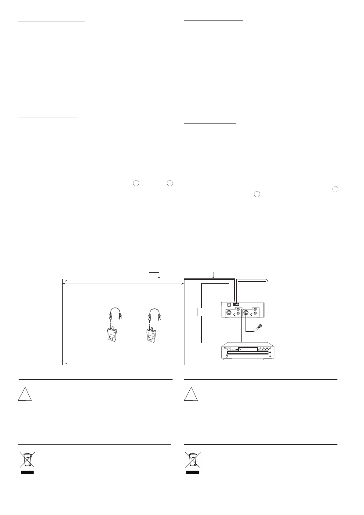
V - EXEMPLE D INSTALLATION (Fig. V)
- Surface = 4m x 8m = 32 m2
- Câble : Longueur = 8+4+8+4+(2x2) = 28m
Section voir tableau § 4.1.1 , 28m = 1mm2ou 1,5 mm2
- Courant maxi en fonction de la largeur de boucle 4 m, et du rap-
port largeur/longueur, 4m/8m = 0,5. Voir tableau § 4-2, 4m et 0,5
donne 3A à ne pas dépasser sur le vumètre.
- Fonctionnement : Le microphone (entrée 1) est prioritaire sur la
musique (entrée 2) et la sirène est prioritaire sur Micro et musique .
VI - MAINTENANCE
En cas de panne :
- Vérifier l’état des fusibles et les remplacer si besoin par des
fusibles de mêmes caractéristiques tel qu’indiqué sur
l’appareil.
- Attendre que l’appareil refroidisse pour s’assurer que la
panne n’est pas due à la protection thermique.
- Sinon retourner l’appareil à l’usine, ou faire appel à un dépan-
neur professionnel.
VII - RECOMMANDATION
En fin de vie du produit, s’il est installé sur le territoire français
(DOM-TOM inlus), veuillez contacter BOUYER pour organiser
sa destruction conformément à la directive DEEE.
Dans le cas contraire, veuillez appliquer la règlementation
locale du pays d’installation du produit.
4.3 Connecting sources
The IL 100 can receive two sources of modulation. Two micro-
phones in ⑫and ⑮, or two auxiliary (0dB) in ⑭and ⑰, or one
microphone in ⑫and one auxiliary in ⑰.
Select for each input MIC or AUX with push-button ⑬and ⑯.
Input 1 and input 2 are mixed. To set priority to input 1, set MP1
on “ON”position (Fig. III).
To broadcast an alarm, a siren can be controlled by a close contact
connected to "switch Alarm" (Fig. II).
Input 1 and input 2 can be mixed. In this case, remove “Talk over”
function. See page1-chapter II.
4.4 Connecting to main power
Connect the main adaptator to the amplifier, then connect to
230V power supply.
Put the switch ①( Fig. I) on “ON“,the indicator ②lights.
4.5 Level adjustment
These adjustments are accessible with a screw driver to avoid
any modification in the future.
Place the 5 front face buttons on the middle.
Apply signals in the inputs and adjust “Loop current” ⑨(Fig. I) in
order that the vumeter displays as current value peak, the value
determined in 4-2.
The adjustments ⑤and ⑥allows to balance the level between
two inputs.
A test listening on the loop with the receiver IL 200 + IL 201
allows to correct the tone adjustment ⑦and ⑧, and level adjust-
ment ⑤, ⑥and ⑨, without exceeding the peak level.
A muffled sound may be caused by iron material in the building;
in this case, make the “Metal loss” function active with MP2 21
and do adjustments with PR2 22 (Fig. III).
V - EXAMPLE OF INSTALLATION (Fig. V)
- Surface = 4m x 8m = 32 m2
- Cable : Length = 8+4+8+4+(2x2) = 28m
Diameter, see table § 4.1.1 , 28m = 1mm2or 1.5 mm2
- Current peak depending on the width of loop 4 m and the
width/length ratio 4m/8m = 0.5 see Table § 4-2, 4m and 0.5 ratio,
gives 3A, not to exceed on the vumeter.
- Operation: The microphone (input 1) is a priority on music (input 2)
and the siren is a priority on Microphone and Music.
VI - MAINTENANCE
In case of failure :
- Check the status of the fuses and replace them if needed by fuses
with the same caracteristics as those indicated on the product.
- Wait until the product has cooled off, to be sure that the failure is
not caused by the thermal relay.
- Otherwise the product has to be sent back to the factory or repai-
red by a recognised dealer.
VII - RECOMMENDATION
This product is subject to European regulation 2002/96/CE
(also called W.E.E.E.).
Please contact your local dealer for destruction in end of life.
4 ________________________________________________________________________________ IL100 / IL200 / IL 201
!
!
INPUT
2
INPUT
1
PHONES
LEVEL
Lecteur CD
CD player
IL 100
Amplificateur de boucle magnétique
Magnetic loop amplifier
Commande sirène
Siren control
230 V
IL 200
IL 201
IL 200
IL 201
Longueur/Length = 8 m
Largeur/Width = 4 m
Boucle inductive au sol
Inductive loop on the floor Longueur de câble torsadé = 2 m
Twist cable length = 2 m
Fig. V

This manual suits for next models

2

Other Bouyer Amplifier manuals

Bouyer SA-3126 Series User manual

Bouyer

Bouyer SA-3126 Series User manual

Bouyer Crescendo SA 3126 Instruction manual

Bouyer

Bouyer Crescendo SA 3126 Instruction manual

Bouyer AM-1032 User manual

Bouyer

Bouyer AM-1032 User manual

Bouyer AP-104 User manual

Bouyer

Bouyer AP-104 User manual

Bouyer AR 1402 User manual

Bouyer

Bouyer AR 1402 User manual

Bouyer SA-1127 User manual

Bouyer

Bouyer SA-1127 User manual

Bouyer SA 3126 User manual

Bouyer

Bouyer SA 3126 User manual

Bouyer AP 3804 User manual

Bouyer

Bouyer AP 3804 User manual

Bouyer AM 1032 I User manual

Bouyer

Bouyer AM 1032 I User manual

Bouyer EB 134 User manual

Bouyer

Bouyer EB 134 User manual

Bouyer AD1-1075 User manual

Bouyer

Bouyer AD1-1075 User manual

Bouyer AM-2015-PACK User manual

Bouyer

Bouyer AM-2015-PACK User manual

Bouyer EXCELLENCE PR 1406 User manual

Bouyer

Bouyer EXCELLENCE PR 1406 User manual

Bouyer GE 3067 User manual

Bouyer

Bouyer GE 3067 User manual

Bouyer AR 1050 User manual

Bouyer

Bouyer AR 1050 User manual

Bouyer EXCELLENCE Series User manual

Bouyer

Bouyer EXCELLENCE Series User manual

Bouyer AS 3066 User manual

Bouyer

Bouyer AS 3066 User manual

Bouyer GE 3267 User manual

Bouyer

Bouyer GE 3267 User manual

Bouyer AS-4000 Series User manual

Bouyer

Bouyer AS-4000 Series User manual

Bouyer AM-2015 User manual

Bouyer

Bouyer AM-2015 User manual

Popular Amplifier manuals by other brands

Boston GT-5750 owner's manual

Boston

Boston GT-5750 owner's manual

PCB Piezotronics 426A05 Installation and operating manual

PCB Piezotronics

PCB Piezotronics 426A05 Installation and operating manual

Electro-Voice Mixer Amplifier MA-1212 brochure

Electro-Voice

Electro-Voice Mixer Amplifier MA-1212 brochure

Gold Note PH-1000 user manual

Gold Note

Gold Note PH-1000 user manual

Avsl Adastra RM Series user manual

Avsl

Avsl Adastra RM Series user manual

Peiying PY-1R127D owner's manual

Peiying

Peiying PY-1R127D owner's manual

JL Audio MV700/5i Connection guide

JL Audio

JL Audio MV700/5i Connection guide

Alpha Power Alpha 89 operating manual

Alpha Power

Alpha Power Alpha 89 operating manual

Sebatron VMPQuadPlus operating manual

Sebatron

Sebatron VMPQuadPlus operating manual

Samson 3710 series Mounting and operating instructions

Samson

Samson 3710 series Mounting and operating instructions

Cicognani Indy STUDIO operating manual

Cicognani

Cicognani Indy STUDIO operating manual

Steg QK200.2 owner's manual

Steg

Steg QK200.2 owner's manual

Cambridge Audio Minx X201 user manual

Cambridge Audio

Cambridge Audio Minx X201 user manual

Blaupunkt Velocity V7000 manual 

Blaupunkt

Blaupunkt Velocity V7000 manual 

Peavey LIGHTING SOLUTIONS LICON 416 user guide

Peavey

Peavey LIGHTING SOLUTIONS LICON 416 user guide

DLS DLS CAD11 owner's manual

DLS

DLS DLS CAD11 owner's manual

Russound X125 installation manual

Russound

Russound X125 installation manual

Pyle Pro PCAU11 user manual

Pyle Pro

Pyle Pro PCAU11 user manual

manuals.online logo
manuals.online logoBrands
  • About & Mission
  • Contact us
  • Privacy Policy
  • Terms and Conditions

Copyright 2025 Manuals.Online. All Rights Reserved.