manuals.online logo
Brands
  1. Home
  2. •
  3. Brands
  4. •
  5. Bouyer
  6. •
  7. Amplifier
  8. •
  9. Bouyer EXCELLENCE Series User manual

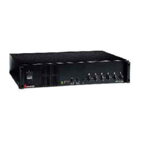
Bouyer EXCELLENCE Series User manual

PR 1106
P
PR
R
1
11
10
06
6
PREAMPLIFICATEUR
MODULAIRE 6 ENTREES
6 WAY MODULAR
PREAMPLIFIER
Série EXCELLENCE/ EXCELLENCE line
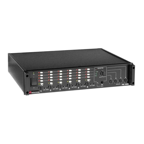
Le PR 1106 est un préamplificateur modulaire monophonique 6
voies fonctionnant en mélange ou en régime prioritaire.
Il est utilisable sur secteur ou sur batterie 24V pour les applica-
tions de sécurité.
Sa conception modulaire permet de multiples configurations (de
1 à 6 entrées et 1 sortie).
Il est doté de correcteurs de tonalité et d’indicateurs de niveaux
nécessaires à une utilisation professionnelle.
Le PR 1106 peut recevoir tous les modules de fonction de la
série Excellence.
L’appareil (2U - 19”) peut être intégré dans une baie en utilisant les
poignées AZ 7 (en option).
• Entrées..............................................................................6 modulaires
ex : avec entrée AZ 1211 et sortie AZ1231
MIC AUX
Rapport S/B ≥ - 60 dB ≥ - 85 dB
Bande passante 65 - 20 kHz 65 - 20 kHz
Distorsion ≤ 0,1 % ≤ 0,05 %
• Tonalité .......................................................... - 10 / + 10 dB 100 Hz
- 10 / + 10 dB 10 KHz
• Sortie .................................................................................. 1 modulaire
Nota : chaque emplacement d'entrée 1 à 6 peut recevoir un
module de sortie en fonction de l'application souhaitée.
• Alimentation :
- Secteur ...................................................................... 230 V - 20 VA
- Batterie .......................................................................... 24 V - 0,7 A
Utilisation entre 20 et 32V - Caractéristiques nominales pour 28,8V
• Dimensions (L x P x H) .................. 425 x 325 x 92 mm (19” 2U)
• Poids ............................................................................................ 5,9 Kg
• Matière - Coloris .............................................................. Métal - Noir
•Livré avec 4 modules d’entrée AZ 1211 et 1 module de sor-
tie AZ 1231.
A l’avant (Fig. I)
Interrupteur “Marche/Arrêt”
Témoin lumineux de mise
sous tension
Indicateur lumineux de
niveau de sortie
Réglage de tonalité grave
Réglage de tonalité aiguë
Réglage de niveau des
entrées
The PR 1106 is a modular 6-channel mono preamplifier which
can operate in mixer or priority mode.
It can be used with the mains supply or with a 24-V battery.
Its modular design makes a wide range of configurations pos-
sible (from 1 to 6 inputs and 1 output).
It has tone correction and level indicator lamps as required for
professional use.
The
PR 1106
is compatible with all the input and output function
modules in the Excellence line.
The unit can be mounted in a 19” rack by using handles AZ 7.
• Inputs ....................................................................................6 modular
example: with input AZ 1211, output AZ 1231
MIC AUX
Signal/noise ratio ≥ - 60 dB ≥ - 85 dB
Bandwidth 65 - 20 kHz 65 - 20 kHz
Distortion ≤ 0,1 % ≤ 0,05 %
• Tone control................................................ - 10 / + 10 dB 100 Hz
- 10 / + 10 dB 10 kHz
• Output .................................................................................. 1 modular
Nota : each input emplacement from 1 to 6 can take an output
module for the application desired.
• Power supply :
- Mains ........................................................................ 230 V - 20 VA
- Battery ............................................................................ 24 V - 0,7 A
Can be used between 20 and 32V - Nominal characteristics for 28.8V
• Dimensions ( L x W x H) .............................. 425 x 325 x 92 mm
• Weight.......................................................................................... 5.9 kg
• Material - Colour............................................................ Metal - Black
•Supplied with 4 AZ 1211 and 1 AZ1231 modules.
III - PRESENTATION
Front panel (Fig. I)
ON/OFF switch
ON indicator lamp
Output level
indicator lamp
Bass tone control
Treble tone control
Input level control
Ce document n'est pas contractuel; toute modification pouvant intervenir sans préavis / This document is not legally binding, we reserve the right to modify descriptions and specifications without notice.
Code 595 656 - 06/05
I - DESCRIPTION I - DESCRIPTION
II - CARACTERISTIQUES TECHNIQUES II - TECHNICAL SPECIFICATIONS
III - PRESENTATION III - PRESENTATION
1
2
3
4
5
6
1
2
3
4
5
6
BOUYER
1 2 3 4 5 6
Fig. I
ATTENTION
The unit is neither water - nor splash proof.
•Mains connection
The unit is supplied ready for mains operation (230V) with earth.
• 24 V battery connection
Connect the + and the - terminals to the battery using ≥ 0,5 mm2
conductors and fast terminal 11 with the connector lock 14
(Fig. II).
•Modulation source and output connections
According to the pins on the modules.
Note: output modules can be installed in input emplacements 1
to 6. The volume control will adjust the output level.
•Installation of a priority system
A priority management board can be installed in this place 7
(Fig. II).
To mount the unit in a 19”
rack, remove the blocks and
the side covers and replace
the covers with the handles
provided in the AZ7 option-
nal rack mounting (Fig III)
After connection, but before switching on, adjust volumes to "0".
Switch the device on using the ON/OFF switch 1 .
The ON indicator lamp 2 lights up.
Adjust levels and tone to the desired level.
A l’arrière (Fig. II)
Emplacement module priorité optionnel
Emplacements modules entrée ou sortie
Emplacement module sortie
Fusible batterie
Bornier débrochable batterie
Prise secteur 230V avec terre
Fusible secteur
Verrouillage du connecteur batterie
ATTENTION :
l’appareil ne doit pas être exposé aux
chutes d’eau et aux éclaboussures
• Branchement secteur
L’appareil est livré pour un fonctionnement en 230V avec terre.
• Branchement batterie 24 V
Raccorder les bornes + et - à la batterie avec des conducteurs
de section ≥ 0,5 mm2et fixer le bornier 11 avec la pièce de ver-
rouillage 14 (Fig. II).
• Branchement sources de modulation et sorties
Suivant brochage indiqué sur les modules.
Nota : les modules sorties peuvent être installés aux emplace-
ments entrées de 1 à 6. Le réglage de volume correspondant
règle alors le niveau de cette sortie.
• Installation d’un système de priorité
L'emplacement 7 (Fig. II) est destiné à recevoir une carte de
gestion des priorités.
Pour monter l’appareil en
baie 19”, démonter les
butées et les caches laté-
raux. Remplacer les caches
latéraux par les poignées
fournies dans le kit AZ 7
(Fig. III).
Après branchements et avant la mise sous tension, mettre les
volumes en position "0"
Mettre l’appareil sous tension à l’aide de l’interrupteur .
Le témoin 2 de mise sous tension s’allume.
Ajuster les niveaux et la tonalité en fonction de l’utilisation désirée.
2 PR 1106
Fig. III
! !
En cas de panne :
Vérifier l’état des fusibles et les remplacer si besoin par
des fusibles de mêmes caractéristiques tel qu’indiqué
sur l’appareil.
Sinon retourner l’appareil à l’usine, ou faire appel à un
dépanneur professionnel.
In case of failure :
Check the status of the fuses and replace them if nee-
ded by fuses with the same caracteristics as those
indicated on the product.
Otherwise the product has to be sent back to the fac-
tory or repaired by a recognised dealer.
! ! •
•
•
•
IV - INSTALLATION IV - INSTALLATION
V - MONTAGE EN RACK V - RACK MOUNTING
VI - UTILISATION VI - USE
VII - MAINTENANCE VII - MAINTENANCE
7
8
9
10
11
12
13
14
Rear panel (Fig. II)
Optional priority module emplacements
Input or output module emplacements
Output module emplacement
Battery fuse
Pluggable battery terminal block
Mains plug 230V with earth
Mains fuse
Battery connector lock
7
8
9
10
11
12
13
14
+
-
AZ 1211
-
+
Mic.
Line
Tlcom..
Remote
+
-
AZ 1211
-
+
Mic.
Line
Tlcom..
Remote
+
-
AZ 1211
-
+
Mic.
Line
Tlcom..
Remote
+
-
AZ 1211
-
+
Mic.
Line
Tlcom..
Remote
AZ 1231
-
+
+
0 dBm +12 dBm
-
Fus - +
BOUYER
PR 1106
ATTENTION
dbrancher le secteur
avant d’ouvrir
CAUTION
disconnect from supply
before opening
230V
50 Hz
Priorité
Priority
1 2 3 4 5 6
Sortie
Output
7 8 9 14
10 11 12 13
Fig. II
7
11
14
7
11 14
1
2
1
2

This manual suits for next models

1

Other Bouyer Amplifier manuals

Bouyer AR 1050 User manual

Bouyer

Bouyer AR 1050 User manual

Bouyer AD1-1075 User manual

Bouyer

Bouyer AD1-1075 User manual

Bouyer AS-4000 Series User manual

Bouyer

Bouyer AS-4000 Series User manual

Bouyer EXCELLENCE PR 1406 User manual

Bouyer

Bouyer EXCELLENCE PR 1406 User manual

Bouyer AM-1032 User manual

Bouyer

Bouyer AM-1032 User manual

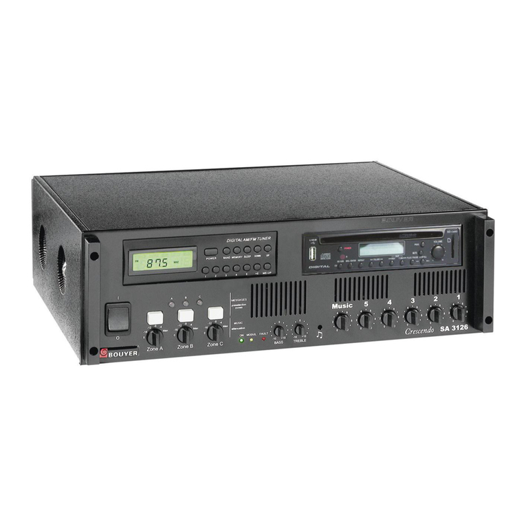
Bouyer Crescendo SA 3126 Instruction manual

Bouyer

Bouyer Crescendo SA 3126 Instruction manual

Bouyer SA-3126 Series User manual

Bouyer

Bouyer SA-3126 Series User manual

Bouyer AM 1032 I User manual

Bouyer

Bouyer AM 1032 I User manual

Bouyer IL 100 User manual

Bouyer

Bouyer IL 100 User manual

Bouyer AP 3804 User manual

Bouyer

Bouyer AP 3804 User manual

Bouyer SA 3126 User manual

Bouyer

Bouyer SA 3126 User manual

Bouyer GE 3267 User manual

Bouyer

Bouyer GE 3267 User manual

Bouyer EB 134 User manual

Bouyer

Bouyer EB 134 User manual

Bouyer AM-2015 User manual

Bouyer

Bouyer AM-2015 User manual

Bouyer SA-1127 User manual

Bouyer

Bouyer SA-1127 User manual

Bouyer GE 3067 User manual

Bouyer

Bouyer GE 3067 User manual

Bouyer AM-2015-PACK User manual

Bouyer

Bouyer AM-2015-PACK User manual

Bouyer AS 3066 User manual

Bouyer

Bouyer AS 3066 User manual

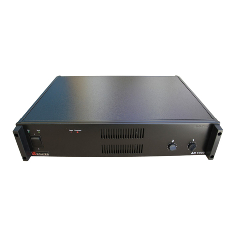
Bouyer AR 1402 User manual

Bouyer

Bouyer AR 1402 User manual

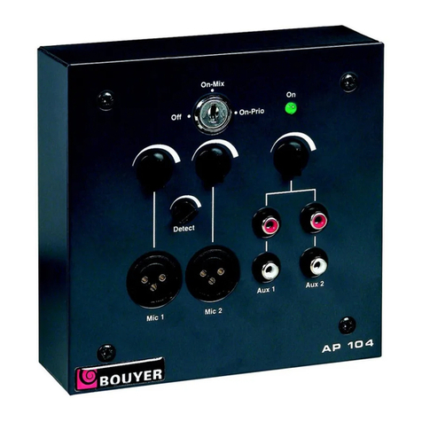
Bouyer AP-104 User manual

Bouyer

Bouyer AP-104 User manual

Popular Amplifier manuals by other brands

Fender Rumble 100 operating instructions

Fender

Fender Rumble 100 operating instructions

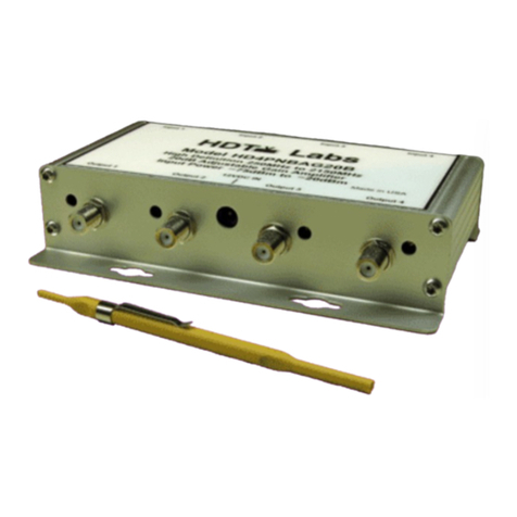
HDTV Labs HD4PNBAG20B instruction manual

HDTV Labs

HDTV Labs HD4PNBAG20B instruction manual

Peavey Vypyr VIP 2 operating manual
Peavey

Peavey Vypyr VIP 2 operating manual
Sharp SX-8000HGY Service manual

Sharp

Sharp SX-8000HGY Service manual

Mitsubishi Electric CV-0MW7G21-92 Service manual

Mitsubishi Electric

Mitsubishi Electric CV-0MW7G21-92 Service manual

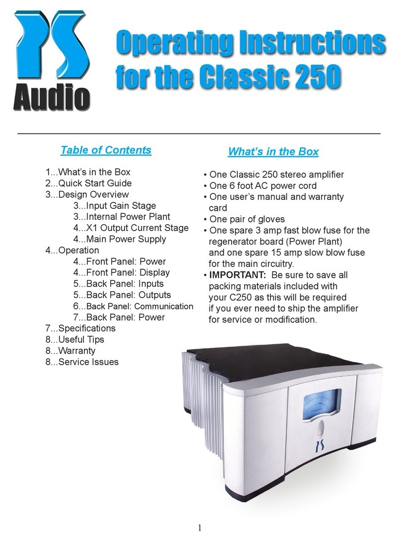
PS Audio Classis 250 operating instructions

PS Audio

PS Audio Classis 250 operating instructions

Loctite 97211 operating manual

Loctite

Loctite 97211 operating manual

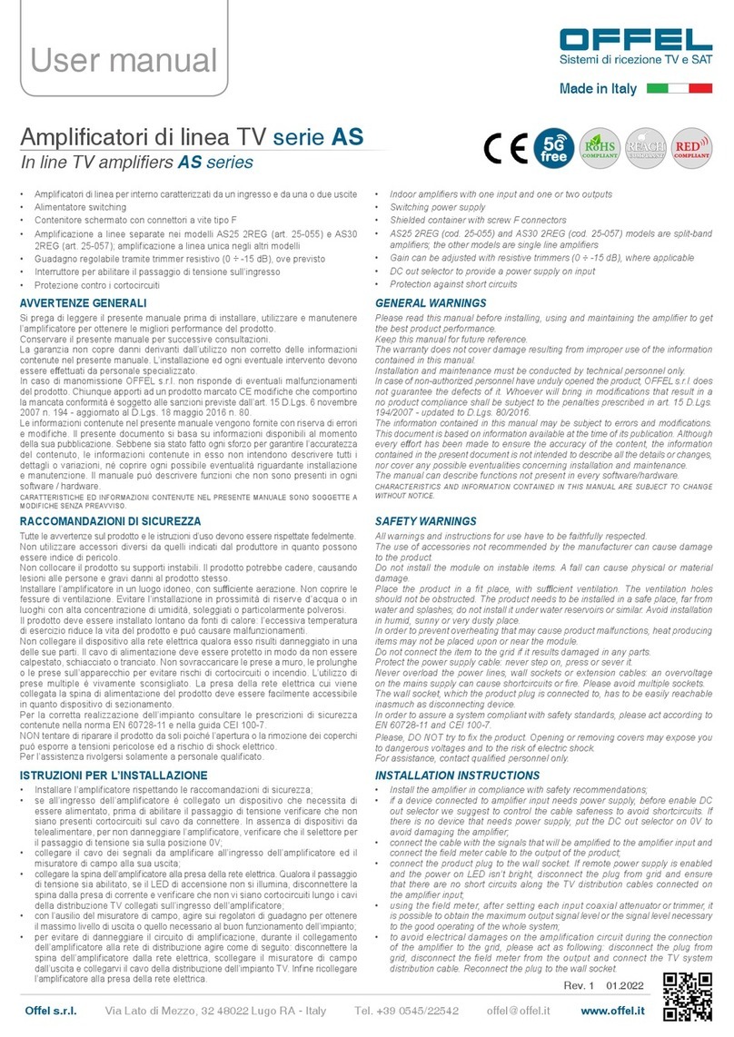
Offel AS Series user manual

Offel

Offel AS Series user manual

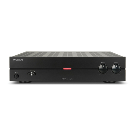
Russound P125 installation manual

Russound

Russound P125 installation manual

Vox Valvetronix AD212 owner's manual

Vox

Vox Valvetronix AD212 owner's manual

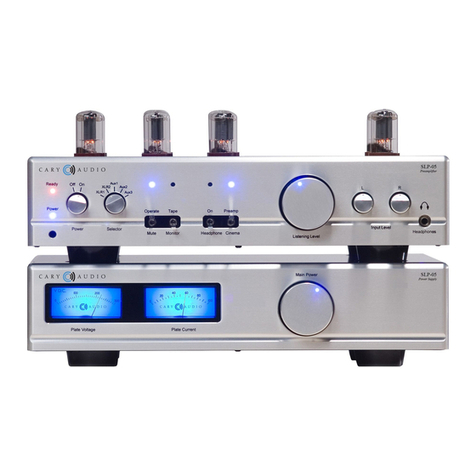
Cary Audio Design SLP 05 owner's manual

Cary Audio Design

Cary Audio Design SLP 05 owner's manual

Behringer Ultrabass BXL3000 Specifications

Behringer

Behringer Ultrabass BXL3000 Specifications

Spectro Acoustics P-101 Handbook of instructions

Spectro Acoustics

Spectro Acoustics P-101 Handbook of instructions

ITC SFB240 Operation manual

ITC

ITC SFB240 Operation manual

Vivanco MA 225 operating instructions

Vivanco

Vivanco MA 225 operating instructions

OSD Audio DAC XA100 user guide

OSD Audio

OSD Audio DAC XA100 user guide

Bellman BE2030 user manual

Bellman

Bellman BE2030 user manual

Soundstream Tarantula Amplifier Series owner's manual

Soundstream

Soundstream Tarantula Amplifier Series owner's manual

manuals.online logo
manuals.online logoBrands
  • About & Mission
  • Contact us
  • Privacy Policy
  • Terms and Conditions

Copyright 2025 Manuals.Online. All Rights Reserved.