Bouyer SA 3126 User manual

AMPLIFICATEUR
MÉLANGEUR 120W
CD MP3 et tuner intégrés
et sélection 3 zones
120W MIXER AMPLIFIER
built-in MP3 CD, tuner and
3 zones selection
425 mm
345
135 mm
Le SA 3126 est un système “tout en un”
intégrant un amplificateur120W à 3 sorties
ligne100V, un préamplificateur à 6 entrées
MIC/AUX avec gestion de priorité, un tuner
AM/FM et un lecteur CD MP3.
Le SA 3126 permet de réaliser très simple-
ment la diffusion de musique et d’appels
dans 3 zones distinctes. La présélection
des zones peut être programmée en face
avant ou bien réalisée au moment de la dif-
fusion depuis le pupitre microphone.
Le SA 3126 au format 3U 19” (Fig. I), est
utilisable sur le secteur 230V et peut être
intégré dans une baie en installant les poi-
gnées AZ 8, en option (Fig. II).
The SA 3126 is an “all in one” system that
includes a 120W amplifier with three
100V line outputs, a preamplifier with 6
MIC/AUX inputs and priority management,
anAM/ FM tuner and an MP3 CD player.
With the AS 3126, it is very easy to broad-
cast background music and make public
address calls/announcements in 3 diffe-
rent zones. Preselection of zones can be
programmed on the front panel or at the
time of making the announcement or
playing background music from the micro-
phone console.
The SA 3126 is in 19” 3U format (Fig. I). It
can be used with 230V mains supply, and
can be mounted in a rack by fitting the AZ8
handles, optional (Fig. II).
Ce document n'est pas contractuel; toute modification pouvant intervenir sans préavis / This document is not legally binding, we reserve the right to modify descriptions and specifications without notice.
Code 596269 - 03/05
I - DESCRIPTION I - DESCRIPTION
II - CARACTERISTIQUES TECHNIQUES II - TECHNICAL SPECIFICATIONS
480 avenue de Paris • 82000 MONTAUBAN • FRANCE
Tél : 33 (0)8 92 70 20 82* (*0,34 €la minute TTC) • Fax : 33 (0)5 63 03 08 26 • http://www.bouyer.com
S
SA
A
3
31
12
26
6
•Puissance................................ 120W RMS
• Distorsion .............................. < 1% à 1kHz
• Bande passante (-3dB) ........ 70 - 17 kHz
• Correction de tonalité
Graves ................................ ±7dB à 100 Hz
Aigus .................................... ±7dB à 10 kHz
Rapport signal/bruit...................... > 80dB
• Entrées
- 5 entrées symétriques MIC/AUX - DIN
- 1 entrée asymétrique AUX
Stéréo/Mono - CINCH
configuration MIC/AUX par inverseurs
- MIC -60dB avec alimentation fantôme
- AUX -10dB symétrique
• Prise insertion ...................... 0 dB CINCH
• Carillon 2 tons :
- Déclenché par la télécommande
- Attribué aux entrées 1, 2 et 3 par confi-
guration des inverseurs
• Sortie ..............0 dB après mélange - DIN
• Sortie haut-parleur :
3 sorties ligne 100V, 120W au total
• Réglage du niveau musique :
1 par zone
6 positions de 0 à Max
• Entrée “Rétablissement de niveau”
commande par contact sec
• Sortie supplémentaire zone 3 :
0dB symétrique pour ampli série AR xxxx
• Alimentation
Secteur........ 230V - 50/60 Hz avec terre
• Consommation ..............................380 VA
• Température d’utilisation.... -5° à +55°C
• Température de stockage -10° à +70°C
• Dimensions (Fig.I).. 425 x345 x135 mm
• Poids ................................................ 10,3 kg
• Option .................... Poignées AZ 8 (Fig.II)
• Power ...................................... 120W RMS
• Distortion .............................. < 1% at 1kHz
• Bandwidth (-3dB) .................. 70 - 17 kHz
• Tone adjustment
Bass .................................... ±7dB at 100 Hz
Treble.................................. ±7dB at 10 kHz
Signal-to-noise ratio ...................... > 80dB
• Inputs
- 5 MIC/AUX - DIN balanced inputs
- 1 AUX unbalanced input
Stereo/Mono - CINCH
MIC/AUX configuration by switches
- MIC -60dB with phantom power supply
- AUX -10dB balanced
• Insertion socket.................... 0 dB CINCH
• 2 tone chime :
- Operated by remote control
- Assigned to inputs 1, 2 and 3 by confi-
guring switches
• Output ..................0 dB after mixing - DIN
• Loudpeaker output :
3 x100V line output, 120W all in all
• Music level control :
1 for each zone
6 positions from 0 to Max
• Input for “Maximum level restoration”
command by dry contact
• Additional zone 3 output :
0dB balanced for AR range amplifier
• Power supply
Mains ...... 230V - 50/60 Hz with ground
• Consumption..................................380 VA
• Operating temperature ...... -5° to +55°C
• Storage temperature ...... -10° to +70°C
• Dimensions (Fig.I).. 425 x345 x135 mm
• Weight ............................................ 10,3 kg
• Optional.................... AZ 8 handles (Fig.II)
Fig. I
Fig. II
AZ 8 - Jeu de poignées
Handle set AZ 8

2SA 3126
III - PRESENTATION III - PRESENTATION
A l'avant (Fig. III)
1Interrupteur de mise sous tension.
2Voyants présélection de zone.
3Touches présélection de zone.
4Boutons de réglage musique.
5Voyants ON - Modulation - Défaut.
6Bouton de réglage grave - aigu.
7Réglage du volume carillon.
8Bouton de réglage du volume Musique et entrée 6.
9Boutons de réglage du volume des entrées “1 - 2 - 3 - 4 - 5”.
10
Lecteur CD MP3 (détail Fig. VI).
Tuner AM/FM (détail Fig. V).
A l'arrière (Fig. IV)
12 Prise de connexion antenne FM.
13 Bornier de connexion antenne AM.
14 Inverseurs de sélection MIC ou AUX pour les entrées de 1 à 5
Activation , Noise-gate.
15 Entrées 1 à 5 sur DIN.
16 Entrée 6 sur CINCH.
17 Sortie symétrique 0 dB.
18 Inverseurs activation carillon sur entrées 1, 2 et 3 /
Configuration priorités / Interrupteur d’insertion.
19 Prises CINCH sortie et entrée pour insertion.
20 Prise RJ45 pour pupitre sélection de zone GM1066.
21 Bornier entrée de commande “Rétablissement de niveau” par
contact fermant.
22 Bornier sortie contact fermant lors des diffusions d’appels.
23 Borniers sorties 100V vers haut-parleurs des zones A - B - C.
24 Sortie symétrique 0dB de la zone C pour ampli série AR xxx.
25 Prise secteur 230V avec terre et fusible secteur.
Liaison 0V/Terre par 100 ( ) ou directe ( ).
A positionner à gauche ( ) en cas de “ronfle” dûe à la
connexion avec un autre équipement.
1
2
3
4
5
6
7
8
9
10
11
12
13
14
15
16
17
18
19
20
21
22
23
24
25
TUNER - AM : 531kHz à 1602 kHz - FM : 87,5 MHz à 107 MHz (Fig. V)
Afficheur fréquence et numéro de station.
Touche “POWER” - La modulation du tuner est normalement
coupée dès qu’un CD est en lecture. Cette touche permet aussi
de couper manuellement le tuner.
Touche “BAND” - Choix de la bande AM ou FM.
Touche “MEMORY” - Mémorisation des stations.
Touche “SLEEP” - En appuyant cette touche, le tuner est pro-
grammé pour fonctionner 90 mn, puis s’arrête. A chaque impul-
sion supplémentaire le temps diminue de 10 mn.
Touche “DOWN” - Recherche des stations - fréquences décrois-
santes. Touche maintenue = défilement rapide.
Touche “UP” - Recherche des stations - fréquences croissantes.
Touche maintenue = défilement rapide.
Touches “1-2-3-4-5” - Mémorisation des stations.
Touche “+5” - Permet de sélectionner un numéro de station
mémorisée supérieur à 5 et jusqu’à 10, ex : 6 = (+5) + (1).
Touche “ME-UP” - Permet de sélectionner le numéro de station
mémorisé suivant.
• Recherche des stations
Utiliser les touches et pour rechercher la station désirée.
Maintenir l’une de ces touches pendant 2 secondes pour lancer la
recherche automatique.
•Mémorisation d’une station
Rechercher la station avec les touches et .
Appuyer sur la touche “MEMORY” .
Composer le numéro de1 à10 avec les touches et .
Appuyer à nouveau sur la touche “MEMORY” .
26
27
28
29
30
31
32
32
32
33
33
33
34
35
36
30
30
34 35
Front (Fig. III)
1
Power switch.
2
Zone preselection indicator lights.
3
Zone preselection buttons.
4
Music setting buttons.
5
ON - Modulation - Fault indicator lights.
6
Bass / treble adjustment buttons.
7
Chime volume adjustment.
8
Music volume and input 6 adjustment button.
9
Volume control button for inputs
“1 - 2 - 3 - 4 - 5”.
10
MP3 CD player (detail Fig. VI).
AM/FM tuner (detail Fig. V).
Rear (Fig. IV)
12
FM antenna connection socket.
13
AM antenna connection terminal.
14
MIC or AUX selection switches for Activation /
Noise-gate inputs 1 to 5.
15
DIN inputs 1 to 5.
16
CINCH input 6.
17
0 dB balanced output.
18
Chime activation switches on inputs 1, 2 and 3 /
Priorities configuration / Insertion switch.
19
CINCH output and input sockets for insertion.
20
RJ45 socket for GM1066 zone selection console.
21
Input terminal connector for “Restoring music volume”
command by normally-open contact.
22
Output terminal connector of normally-open contact during
public address announcements.
23
Connection terminal for 100V outputs to loudspeakers of zones A - B - C.
24
0dB balanced output of zone C for AR range amplifier.
25
230V mains plug with ground connection and mains fuse.
0V/Ground link via 100 ( ) or direct ( ).
To be positioned on left ( ) if there is any “hum” due to
connection with other equipment.
1
2
3
4
5
6
7
8
9
10
11
12
13
14
15
16
17
18
19
20
21
22
23
24
25
26
TUNER - AM : 531kHz to 1602 kHz - FM : 87,5 MHz to 107 MHz(Fig. V)
Frequency and station number display.
“POWER” button - Tuner modulation is normally turned off
when a CD is being played. This button may also be used to
manually turn off the tuner.
“BAND” button - For choosing AM or FM waveband.
“MEMORY” button - Station memorization.
“SLEEP” button - When this button is pressed, the tuner is program-
med to operate for 90 minutes and to then stop. Every time the but-
ton is pressed, this length of time decreases by 10 minutes.
“DOWN” button - Station search by increasing frequencies.
Hold down button for fast scan.
“UP” button - Station search by decreasing frequencies. Hold
down button for fast scan.
“1-2-3-4-5” buttons - Station memory.
“+5” button - For selecting a memorized station No. higher
than 5 and up to 10, e.g., 6 = (+5) + (1).
“ME-UP” button - For selecting the next memorized station No.
•
Station search
Use and buttons to find the required station.
Push on the key during 2 seconds to start the automatic search.
•
Station memory
Search for the station, using buttons
and .
Press the “MEMORY” button
.
Enter the number from 1 to 10, using buttons and
.
Press the “MEMORY” button again.
27
28
29
30
31
32
32
32
33
33
33
34
35
36
30
30
34 35

SA 3126 3
Télécom.
Remote
31
524
Entrée symétrique
Balanced input 31
524
Sortie symétrique
Balanced output
1 2 3 4 5 6
SORTIE
OUTPUT
0dB
PRIORITY
MODE
230V
50/60Hz
FUS.T4A
AUX
MIC
Configuration
AUX / MIC
1 2 3 4 5 ON
AUX / MIC AUX
ENTREES
INPUTS
OFF
INSERTION
MONTAUBAN - FRANCE
ATTENTION :
SORTIE DE
VENTILATION
CAUTION :
AIR COOLING
OUTPUT
ATTENTION :
débrancher le
secteur avant
d'ouvrir
CAUTION :
disconnect
from supply
before opening
Console
Micro
Pupitre
SORTIES ZONES OUTPUTS
0 dB
3
1
2
0 dB
IN
C
100 V
AM
FM
A B C
15
12 13 20 21 22 23 24 25
14 16 17 18 19
FMAM
26
Fig. IV
I
0
Music 5 4 3 2 1
Crescendo SA 3126
2
3
1
4 5 6 7 8 9
DIGITAL AM/FM TUNER
11 10
Fig. III
34
27 28 29 30 31 32 33
35 36
POWER
BAND MEMORY SLEEP DOWN UP
1 2 3 4 5 +5 ME-UP
Fig. V
/
DOWN/REW UP/FF STOP PLAY/PAUSE OP/CL
HUNDRED TEN UNIT REPEAT -FOLDER SKIP-
REMOTE
EC-330R
discdisc
COMPACT
DIGITAL AUDIO
37
43 44 45 46 47
39 40 41 42
38
Fig. VI
1 6 mixing inputs with remote control __________
2 5 mixing inputs without remote control E6 ____
3 E1 > E2 > E3 > E4 > E5 > E6 __________________
4 E1 > E2 + E3 + E4 + E5 + E6 __________________
5 E1 > E2 > E3 + E4 + E5 + E6 __________________
6 E1 > E2 # E3 > E4 + E5 + E6 __________________
7 E1 > E2 # E3 # E4 # E5 > E6__________________
8 E1 # E2 # E3 # E4 # E5 > E6 ________________
Symbols :
E1 + E2 : E1 in mixing with E2
E1 > E2 : E1 taken priority over E2
E1 # E2 : First speaking priority
E4 … E5 : E4 and E5 operates without remote control
4 5 6
Priority Switch
18
(Fig. IV)
1 6 entrées en mélange sans télécommande ____
2 5 entrées en mélange avec télécommande E6 __
3 E1 > E2 > E3 > E4 > E5 > E6
4 E1 > E2 + E3 + E4 + E5 + E6 __________________
5 E1 > E2 > E3 + E4 + E5 + E6 __________________
6 E1 > E2 # E3 > E4 + E5 + E6 __________________
7 E1 > E2 # E3 # E4 # E5 > E6__________________
8 E1 # E2 # E3 # E4 # E5 > E6 ________________
Signification des symboles :
E1 + E2 : E1 en mélange avec E2
E1 > E2 : E1 prioritaire sur E2
E1 # E2 : Priorité au premier appelant
E4 … E5 : E4 et E5 fonctionnent sans télécommande
Priorité Inverseur
18
(Fig. IV)
4 5 6
Fig. VII
4SA 3126
MONTAUBAN - FRANCE
1 2 3 4 5
SA 3126
1 2 3 4 5 6
1 2 3 4 5 6 7 8
Zone A
Zone B
Zone C
120W max.
Fig. VIII
MONTAUBAN - FRANCE
1 2 3 4 5 6
1 2 3 4 5
SA 3126
1 2 3 4 5 6 7 8
Zone A
Zone B
Zone C
120W max.
Fig. IX
MONTAUBAN - FRANCE
1 2 3 4 5 6 7 8
1 2 3 4 5 6
GM 1066
1 2 3 4 5
SA 3126
Zone A
Zone B
Zone C
120W max.
GM 1052
GZ 1201
+
AZ 1215
Autocom.
Fig. X
MONTAUBAN - FRANCE
1 2 3 4 5
SA 3126
Zone A
Zone B
Zone C
120W max.
AR 1180
180W max.
Total
300W
max.
Fig. XI
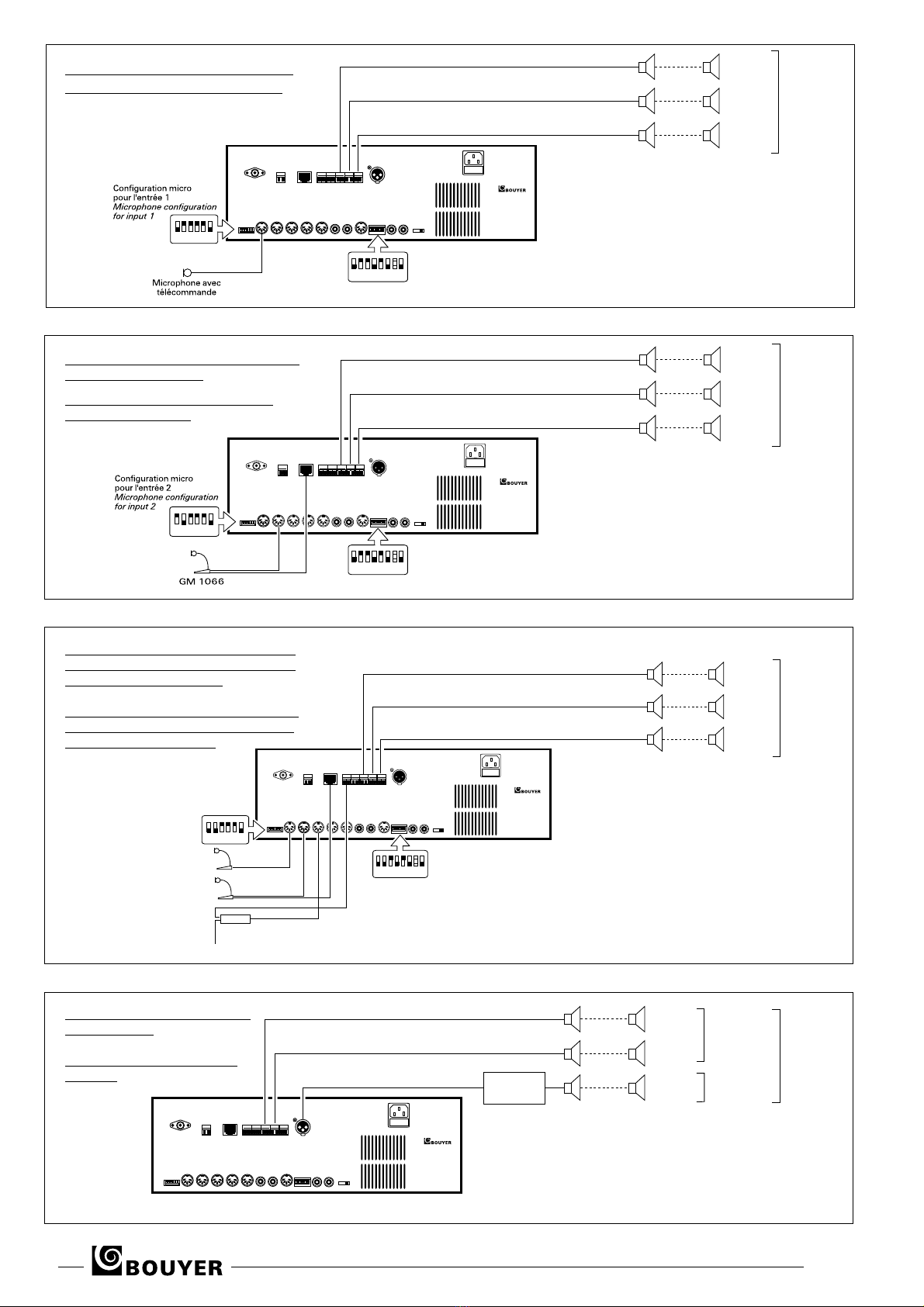
Installation de base avec 1 microphone
Basic installation with 1 microphone
Installation avec un pupitre microphone
avec sélection de zones
Installation with a zone selection
microphone console
Installation avec 1 pupitre microphone,
1 pupitre micro avec sélection de zones
et 1 interface téléphonique
Installation with 1 microphone console,
1
zone selection microphone console
and 1 telephone interface
Installation avec un amplificateur
supplémentaire
Installation with an additional
amplifier

SA 3126 5
• Branchement secteur 2 (Fig. IV)
L’appareil est livré pour un fonctionnement en 230V avec terre.
•Branchement des entrées 15 (Fig. IV)
Les entrées de 1 à 5 (DIN) peuvent recevoir des microphones (élec-
tret ou électro-dynamique) ou des sorties auxiliaires (-10 dBu) selon
la configuration des inverseurs correspondants 14 (Fig. IV).
L’entrée 6 peut recevoir une sortie auxiliaire stéréo (CINCH) diffusée
en mono.
Attention - Le réglage de volume de l’entrée 6 “MUSIC”en face
avant est aussi utilisé pour les sources intégrées Tuner et CD. Si
cette entrée doit être utilisée, couper le tuner en appuyant sur la
touche “POWER” et ne pas mettre de CD en lecture.
• Sortie mélange 0dBu symétrique (DIN) 17 (Fig. IV)
Cette sortie peut être utilisée pour attaquer l’entrée d’un autre équi-
pement.
• Prise insertion (CINCH) 19 (Fig. IV)
Ces prises permettent d’insérer un appareil dans la chaîne d’ampli-
fication, ex : un équaliseur.
Attention - Dans ce cas l’inverseur “8” (Fig. IV) doit être ouvert
(en haut). Si l’insertion n’est pas utilisée, cet inverseur doit rester
fermé (en bas).
• Carillon
Un carillon 2 tons peut être déclenché par la télécommande des
entrées “1, 2 et 3”. Pour activer cette fonction, basculer les inver-
seurs “1, 2 et 3” correspondant 18 (Fig. IV). Ce carillon est généra-
lement utilisé pour précéder les messages d’annonce à partir d’un
microphone doté d’une télécommande. Un réglage de niveau est
prévu 7 (Fig. III).
• Noise-gate
Cette fonction a pour effet de supprimer le léger bruit de fond de
l’amplificateur en absence de signal. Pour obtenir cette fonction,
basculer l’inverseur “6” 14 (Fig. IV) vers le haut.
• Priorités (Fig. VII)
REMARQUE !
Pour le fonctionnement en mode priorité, les sources doivent déli-
vrer une télécommande - contact entre 2 et 4 de la prise DIN.
Si tel n’est pas le cas, par exemple pour un lecteur CD, le connec-
ter en entrée 4 ou 5 ou 6 et configurer selon la ligne 5 du tableau.
L’entrée 6 fonctionne toujours sans télécommande.
Pour les applications de base, voir la position des inverseurs pages
suivantes.
IV - INSTALLATION IV - INSTALLATION
CAUTION !
The unit is neither water - nor splash proof.
Before any manipulation, disconnect the mains cable.
After manipulation, put back the cover and check that
the “earth” wire (yellow + green) is connected properly.
!
ATTENTION !
L’appareil ne doit pas être exposé aux chutes d’eau et
aux éclaboussures.
Avant toute intervention, déconnecter le câble secteur.
Après l’intervention, refermer l’appareil et vérifier que
le fil de terre (jaune et vert) soit bien connecté.
!
Lecteur CD - Compatible CD-RW et MP3 (Fig. VI)
MP3 - Bit rate = 32 kbps ∼ 320 kbps - Sampling : 32 kHz - 44,1 kHz -
48 kHz - CD gravé selon la norme ISO 9660.
Tiroir du CD.
Afficheur : Nombre et numéro de plage (CD audio) - Nombre et
numéro de répertoire et de fichier MP3.
Touches de recherche des plages ou fichiers précédents ou suivants.
Touche d’arrêt lecture.
Touche lecture/pause.
Touche d’ouverture et fermeture du tiroir CD.
Touche sélection du chiffre des centaines pour les fichiers MP3.
Touche sélection du chiffre des dizaines pour les fichiers MP3.
Touche sélection du chiffre des unités pour les fichiers MP3.
Touche répétition de lecture d’une plage ou de tout le CD (CD
audio) et d’un fichier, d’un répertoire ou de tout le CD (CD MP3).
Touche de sélection du répertoire précédant ou suivant (CD MP3).
47
37
38
39
40
41
42
43
44
45
46
25
15
14
17
19
18
18
14
7
CD player - CD-RW & MP3 compatible
(Fig. VI)
MP3 - Bit rate = 32 kbps ∼ 320 kbps - Sampling : 32 kHz - 44,1 kHz -
48 kHz -
CD burned in accordance with ISO 9660.
CD tray.
Display: Total quantity of tracks and track No. on Audio CD -
Total quantity, folder No. and file No. of MP3 files.
Buttons for searching previous or next tracks or files.
Stop button.
Play/Pause button.
CD tray open/close button.
Button for selecting the hundreds digit of an MP3 file No.
Button for selecting the tens digit of an MP3 file No.
Button for selecting the units digit of an MP3 file No.
Button for repeating play of (a) a track or entire CD (of an
Audio CD), or (b) a file, folder, or entire CD (of an MP3 CD).
Button for selecting previous or next folder (on an MP3 CD).
47
37
38
39
40
41
42
43
44
45
46
• Mains connection (Fig. IV)
This appliance is supplied for operation with a grounded 230V
mains supply.
•
Connections to inputs
(Fig. IV)
Inputs 1 to 5 (DIN) can receive electret or electro-dynamic
microphones or auxiliary outputs (-10 dBu) according to the
configuration of the corresponding switches (Fig. IV).
Input 6 can receive an auxiliary stereo output (CINCH) transmit-
ted in mono.
Caution: The volume adjustment of “MUSIC” input 6 on the
front panel is also used for the built-in Tuner and CD sources. If
this input is to be used, power down the tuner by pressing the
“POWER” button and do not play the CD player.
•
Balanced 0dBu mixer output (DIN)
(Fig. IV)
This output may be used for sending to the input of other equip-
ment.
•
Insertion socket (CINCH)
(Fig. IV)
These sockets are used for inserting an appliance (such as an
equalizer) in an amplification system .
Caution: In this case, switch “8” 18 (Fig. IV) must be turned on
(up). If insertion is not used, then this switch must stay off (down).
• Chime
A 2-tone chime can be activated by the remote control of inputs
“1, 2 & 3”. To activate this function, position the corresponding
switches “1, 2 & 3” (Fig. IV). This chime is generally used to
precede announcement messages made from a remote control
microphone. A volume control is provided (Fig. III).
• Noise-gate
This function eliminates the amplifier’s slight background noise
when there is no signal. To use this function, move switch “6”
(Fig. IV) upwards.
• Priorities (Fig. VII)
NOTE !
For operation in priority mode, sources must send a remote
control signal - contact between 2 and 4 of the DIN plug.
If this is not the case, e.g., for a CD player, connect it to input 4,
5 or 6 and configure it as in line 5 of the table.
Input 6 always operates without a /remote control.
For basic applications, see the positions of switches on the fol-
lowing pages.
25
15
14
17
19
18
18
14
7
6
• Branchement des haut-parleurs “A-B-C” 23 (Fig. IV)
Utiliser exclusivement des haut-parleurs pour ligne 100V.
Raccorder les haut-parleurs aux sorties ligne 100V. La puissance
totale des haut-parleurs ne doit pas dépasser 120W.
Lorsque la puissance demandée dépasse 120W, il est possible de
rajouter un amplificateur supplémentaire sur la sortie 0dB de la
zone C (Fig. IV). Ainsi on dispose de 120W pour les zones A et B,
et de la puissance de l’amplificateur supplémentaire pour la zone C.
Cette sortie est spécialement conçue pour une utilisation avec les
amplificateurs de la série AR (entrée sur transfo).
• Rétablissement de niveau
A chaque appel avec un microphone à télécommande connecté en
l’entrée 1, les atténuations attribuées à la musique par les boutons
(Fig. III) sont rétablies au niveau maximum.
• Antennes
Connecter l’antenne FM (en T) en 12 (Fig. IV) et fixer cette antenne
verticalement contre une paroi non métallique.
Connecter l’antenne AM (cadre) en 13 (Fig. IV).
VI - MAINTENANCE VI - MAINTENANCE
En cas de panne :
•
Vérifier l’état du fusible et le remplacer si besoin par un fusible
de mêmes caractéristiques tel qu’indiqué sur l’appareil.
•
Attendre que l’appareil refroidisse pour s’assurer que la panne
n’est pas due à la protection thermique.
•
Sinon retourner l’appareil à l’usine, ou faire appel à un dépan-
neur professionnel.
In case of failure :
•Check the status of the fuse and replace them if needed by
fuse with the same caracteristics as those indicated on the
product.
•Wait until the product has cooled off, to be sure that the failu-
re is not caused by the thermal relay.
•Otherwise the product has to be sent back to the factory or
repaired by a recognised dealer.
!!
23
24
4
12
13
1/ Installation de base (Fig. VIII, page 4)
Fonctions :
- Diffusion de musique : A la mise sous tension, le tuner est diffusé.
Dès qu’un CD est en lecture, il prend la priorité sur le tuner. Le
tuner peut aussi être coupé par la touche “POWER” 27 (Fig. V),
par exemple lorsqu’une source de musique extérieure est connec-
tée à l’entrée 6 (2 x CINCH).
Le niveau musique est réglé par le volume “MUSIC” (Fig. III) et
par un commutateur pour chacune des zones.
- Diffusion d’appel avec un microphone à télécommande connecté
impérativement en entrée 1. Les zones de diffusion de ces appels
sont présélectionnées avec les trois boutons poussoirs 3 (Fig. III)
en face avant du SA 3126. Les atténuations affectées à la
musique sont rétablies à leur niveau maximum pendant l’appel.
Un carillon 2 tons est émis à l’activation de la télécommande du
microphone et la musique est coupée durant la diffusion d’appel.
Un contact sec fermant (0,5A-125V) est délivré pendant l’appel
sur le bornier (Fig. IV).
2/ Installation avec un pupitre de sélection (Fig. IX, page 4)
Fonctions :
- La présélection des zones d’appel est faite sur les 3 premières
touches du pupitre microphone GM1066 impérativement
connecté en entrée 2, et en (Fig.IV).
- Les autres fonctions sont identiques à l’installation de base.
3/ Installation avec deux pupitres et une interface téléphonique
(Fig. X, page 4)
Fonctions :
- Les appels provenant de l’interface téléphonique sont diffusés
dans les zones présélectionnées en face avant du SA 3126.
- En cas de simultanéité des appels, le microphone GM 1052 est
prioritaire sur le microphone GM 1066, lequel est prioritaire sur
l’interface téléphonique. La priorité s’applique sur le signal audio
et sur la présélection des zones.
-Les autres fonctions sont identiques à l’installation de base.
4/ Installation avec un amplificateur supplémentaire (Fig. XI, page 4)
Fonctions :
- L’amplificateur supplémentaire est applicable dans tous les cas
d’exemples précédants et ne change pas le comportement des
atténuations et des présélections
.
V - EXEMPLES D’APPLICATION V - EXAMPLES OF APPLICATION
28
22
20
3
8
•
Connecting loudspeakers
“A-B-C” (Fig. IV)
Connect the loudspeakers to the 100V line outputs. The total
power of loudspeakers must not be more than 120W.
When the required power is more than 120W, an additional
amplifier may be added to the 0dB output of C zone (Fig. IV).
This arrangement will obtain 120W for zones A and B, and the
power of the additional amplifier for zone C. This output has been
designed for using with AR amplifier range (transformer inpout).
• Restoring volume control
Every time a public address announcement is made with a remo-
te control microphone connected to input 1, the music volume
attenuations set by the control buttons (Fig. III) are returned
to the maximum level.
• Antennas
Connect the T-shaped FM antenna to (Fig. IV) and fasten this
antenna vertically against a non-metal surface.
Connect the AM antenna frame to (Fig. IV).
23
24
4
12
13
1/ Basic installation (Fig. VIII, page 4)
Functions :
- Playing background music. On powering up, the output from the tuner
is broadcast via the system.
When a CD is played, it takes priority over the tuner. The tuner can also
by turned off by pressing the “POWER” button (Fig. V), for example,
when an external music source is connected to input 6 (2 x CINCH).
The music volume level is adjusted by the “MUSIC” volume control
(Fig. III) and by a selector switch for each of the zones.
- Public address announcements must be made using a remote control
microphone that is connected to input 1. Using the three pushbuttons
(Fig. III) on the SA 3126’s front panel, preselect the zones to which
announcements are to be made. The music volume attenuations are
returned to their maximum level during the announcement.
A 2-tone chime is sounded when the remote control microphone is
activated, and the music is cut off while the announcement is being
made. A closing dry contact (rating 0.5A-125V) is delivered during the
call on the terminal (Fig. IV).
2/
Installation with a selection console
(Fig. IX, page 4)
Functions :
- Zones in which announcements are to be made are preselec-
ted on the first 3 buttons of the microphone console GM1066,
which must be connected to input 2, and to (Fig.IV).
- The other functions are identical to those of the basic installation.
3/ Installation with two consoles and a telephone interface
(Fig. X, page 4)
Functions :
- Announcements from the telephone interface are made in the
zones preselected on the SA 3126’s front panel.
- If announcements are made simultaneously, microphone
GM1052 takes priority over microphone GM1066, which takes
priority over the telephone interface. Priority applies to the audio
signal and the zones preselection.
- The other functions are identical to those of the basic installation.
4/
Installation with an additional amplifier
(Fig. XI, page 4)
Functions :
-
The additional amplifier is applicable in all cases of previous
examples, and it does not change the attenuation and prese-
lection procedures and functions.
22
20
3
8
28
Table of contents
Other Bouyer Amplifier manuals

Bouyer
Bouyer AD1-1075 User manual

Bouyer
Bouyer EB 134 User manual

Bouyer
Bouyer AS-4000 Series User manual

Bouyer
Bouyer EXCELLENCE Series User manual

Bouyer
Bouyer SA-1127 User manual

Bouyer
Bouyer AS 3066 User manual

Bouyer
Bouyer EXCELLENCE PR 1406 User manual

Bouyer
Bouyer GE 3067 User manual

Bouyer
Bouyer Crescendo SA 3126 Instruction manual

Bouyer
Bouyer AR 1402 User manual

Bouyer
Bouyer SA-3126 Series User manual

Bouyer
Bouyer GE 3267 User manual

Bouyer
Bouyer AM 1032 I User manual

Bouyer
Bouyer IL 100 User manual

Bouyer
Bouyer AP 3804 User manual

Bouyer
Bouyer AM-1032 User manual

Bouyer
Bouyer AM-2015-PACK User manual

Bouyer
Bouyer AP-104 User manual

Bouyer
Bouyer AM-2015 User manual

Bouyer
Bouyer AR 1050 User manual


