Bouyer SA-1127 User manual

SA-1127
Mixer amplifier with sources 240W
120W - 7 inputs –6 zones
BI –241 Masques Notices-long_A
Code : 596672
Date : 08 / 2021
Version : 1
BOUYER INDUSTRIE
82000 Montauban –France Fax : +33 (0)5 63 03 08 26 www.bouyer.com
I. Introduction.....................................................................................................................................................1
II. Specification ....................................................................................................................................................2
III. Features.......................................................................................................................................................3
IV. Installation and connections .......................................................................................................................5
1. Input Jack 6.35mm connection (front panel)..............................................................................................5
2. Power connection........................................................................................................................................5
3. Speakers‘ lines outputs connection.............................................................................................................5
4. FM antenna connection ..............................................................................................................................6
5. XLR inputs connection .................................................................................................................................6
6. RCA inputs connection ................................................................................................................................6
7. PGM-1247-V2 paging console connection ..................................................................................................6
V. Usage ...............................................................................................................................................................6
VI. Preventive measures.................................................................................................................................11
I. Introduction
This mixer amplifier is made with a switching power supply, 7 inputs pre-amplification section, 120W class
D power amplification stage, a zone selection stage (6) with independent attenuation, a multiple sources module
with FM Tuner, USB reader, micro SD card reader and Bluetooth. All integrated into a 2U enclosure that can be
placed on a table or integrated into a 19 "rack.
This document is not legally binding, we reserve the right to modify descriptions and specifications without notice.
Summary

2
BOUYER INDUSTRIE
82000 Montauban –France Fax : +33 (0)5 63 03 08 26 www.bouyer.com
II. Specification
Input 1 (Mic1 / face avant)
Sensitivity
- 40dBu
Type
Mono
Connection
Jack 6.35mm female
Input 2 (Mic2/Line2)
Input 3 (Mic3/Line3)
Input 4 (Mic4/Line4)
Sensitivity
- 36,5dBu / - 10dBu
Type
Electronic symetric
Connection
XLR female
Alim fantôme
+48V (MIC)
Input 5 (Line5)
Input 6 (Line6)
Input 7 (EMC / priority)
Sensitivity
0dBu
Type
Stereo
Connection
2 x RCA females
Input 8 (Paging)
Type
Dedicated to PGM-1247-V2 console
Connection
RJ45 female
USB / micro SD (TF) reader
Type of files
MP3 / WAV / APE
Max. size supported
32 Go
Bluetooth 4.2
Max. range
10 m
Output (Out)
Sensitivity
0dBu
Type
Stereo
Connection
2 x RCA females
Outputs 100V
Level
100V / 70V / 16Ω / 8Ω / 4Ω
Power
120 W
Bandwidth
100 - 16Khz
Distortion
< 0.5% (@ 1Khz)
Type
Transformers
Connection
2 points screws terminals
Settings
Tone
Bass (+/-6dB)
Treble (+/-5dB)
Power
Mains
110V-265V AC 50Hz-60Hz
Consumption 1/8 Pmax
pink noise
47W
Battery
24V DC
Consumption 1/8 Pmax
pink noise
40W
Temperature
Use
-10° / + 45°C
Storage
-20° / + 75°C
Dimensions (l x p x h)
2U / rack 19''
438 x 405 x 88mm
Weight
9.5 Kg

3
BOUYER INDUSTRIE
82000 Montauban –France Fax : +33 (0)5 63 03 08 26 www.bouyer.com
III. Features
Front panel
In this part we will describe in detail the front panel and all available functionalities..
Zone (1) is composed of:
- An on / off switch to turn the product on or off
- A green "AC" LED (mains power)
- A green "DC" LED (battery power)
Zone (2) is composed of (left to right):
- Input "MIC1" (Microphone input in Jack 6.35mm with the 2nd highest priority level after the Input "EMC"
which will be described later)
- A switch for adjusting the volume of the Input "MIC1"
- A switch for adjusting the volume of the Input "INPUT2"
- A switch for adjusting the volume of the Input "INPUT3"
- A switch for adjusting the volume of the Input "INPUT4"
Zone (3) is the embedded USB / FM / micro SD / Bluetooth player, composed of:
- A backlit screen
- Parameters / selection buttons (detailed in part V)
- An Input for micro SD card on the left
- An Input for USB key on the right
Zone (4) is composed of (left to right):
-Volume switch for input ‘’LINE5’’
-Volume switch for input ‘’LINE6’’

4
BOUYER INDUSTRIE
82000 Montauban –France Fax : +33 (0)5 63 03 08 26 www.bouyer.com
Zone (5) is composed of (for all 6 zones available):
- A green LED indicating whether the area concerned is activated or not
- A zone selection button (top)
- A volume control switch (bottom)
Note: In addition, an "ALL" button allows you to directly select all 6 zones at once
Zone (6) is composed of (left to right):
- A bass control switch (BASS)
- A treble control switch (TREBLE)
- A general volume control switch (MASTER)
Zone (7) is composed of (top to bottom):
- A yellow LED when the product is in protection (PROT)
- A red LED when the audio signal is saturated on the input (CLIP)
- 3 green LEDs that light up depending on the signal level
Rear panel
In this part we will describe in detail the rear panel and all available features.
Zone (1) is composed of:
-A mains plug + fuse location
-24V DC input for battery
Zone (2) is composed of 100V / 70V / 16Ω/ 8Ω/ 4Ωline output for all zones
Zone (3) is composed of 6 (100V) line outputs for 6 zones
Zone (4) is composed of:
-An FM antenna plug
-A switch to manage ‘’MIC1’’ attenuation (front)

5
BOUYER INDUSTRIE
82000 Montauban –France Fax : +33 (0)5 63 03 08 26 www.bouyer.com
Zone (5) is composed of (for inputs 2 / 3 / 4):
-XLR female input
-A switch to select mic. or line level on the left and
with or without phantom power on the right
Zone (6) is composed of (for inputs 5 / 6 / ‘’EMC’’ and output ‘’OUT’’):
-2 x RCA females inputs
Note: ‘’EMC’’ input has the highest priority in the system
Zone (7) is composed of RJ45 female input for PGM-1247-V2 paging console
(detailed later)
IV. Installation and connections
WARNING !
The device must not beexposed to falling water and splashing water.The device must imperatively be connected
to a power supply socket with earth conductor. Do not obstruct the ventilation openings.
1. Input Jack 6.35mm connection (front panel)
The use of a stereo jack allows a balanced signal to be connected to the "MIC1" input present in zone (2) on the
front panel.
With Jack 6,35mm mono : T = hot point, S = ground (in this case of unbalanced
connection, the output signal will be attenuated by 6dB).
2. Power connection
Use the mains cable supplied with the product and plug it on the plug of the zone (1).
If a 24V battery power supply is chosen, connect the battery to the 2-point input of the zone (2).
3. Speakers‘ lines outputs connection
Connection must be made on zone (2) or (3) connectors.
Each of the outputs is accessible via a 2-point screw terminal block.
Mono 6,35mm jack plug
Stereo 6,35mm jack plug
Jack 6,35mm Mono
Jack 6,35mm Stereo

6
BOUYER INDUSTRIE
82000 Montauban –France Fax : +33 (0)5 63 03 08 26 www.bouyer.com
4. FM antenna connection
The connection is made on the FM antenna socket of zone (4).
Screw the coaxial cable supplied with the product onto the socket.
5. XLR inputs connection
The connection is made on the female XLR sockets located on the rear panel in zone (5).
Pin number
Type
1
Ground
2
+
3
-
To obtain line level, put switch 1 on the "ON" position downwards.
To obtain a microphone level, put switch 1 up.
If the console connected to the XLR socket accepts phantom power supply,
put switch 2 on the "ON" position downwards.
6. RCA inputs connection
The connection is made on the female RCA sockets on the rear panel in zone (6).
7. PGM-1247-V2 paging console connection
The connection is made on the RJ45 socket on the rear panel in zone (7).
V. Usage
To turn on the product, push the "POWER" switch in zone (1) upwards.
Depending on the power supply chosen, one of the LEDs above "POWER" will light up green. (If mains supply =
"AC" LED / if 24V supply = "DC" LED)
As presented in part ‘’ III. Features '', it is possible to select one or more zones using the upper zone buttons
(5) on the front panel and to adjust their output volumes independently using the switches below each zones.
A general volume "MASTER" is also available in zone (6).
To adjust the volume of each input independently, turn the corresponding switches in zones (2) and (4).

7
BOUYER INDUSTRIE
82000 Montauban –France Fax : +33 (0)5 63 03 08 26 www.bouyer.com
To adjust the bass and treble levels, turn the switches in zone (6).
To use zone (3) integrated USB / FM / micro SD / Bluetooth reader, refer to the following table.
To use the remote control associated with the embedded player, refer to the following table:
Mode used
Touche
Tuner FM
USB
Bluetooth
Turn on/off the module
Each time you press, a new mode is activated: USB / micro SD / FM / Bluetooth
1 short press mute the sound
1 short press saves the selected frequency
in the stored list
1 long press deletes the displayed
frequency from the stored list
1 short press = playback in progress paused
1 new short press = restart reading
1 short press = previous saved station
1 short press = previous track
1 short press = next saved station
1 short press = next track
Mode utilisé
Touche
Tuner FM
USB / micro SD
Bluetooth
One short press, a new mode is activated : USB / micro SD / FM / Bluetooth
To connect to Bluetooth, search for ‘’Ulisse’’ / code to connect = 1234
1 short press = save frequency in the
memorized list
1 long press = delete frequency from
the memorized list
1 short press = playback in progress paused
1 new short press = restart reading
1 short press = frequency - 0.1
Each time you press, a new folder on the USB or
micro SD key is activated
Equalizer choice :
-NOR = normal
-ROCK / POP /CLAS /JAZZ
-CONU = Vocal
1 short press = frequency + 0.1
1 long press> 3s = automatic scan of all
frequencies.
The player stores the stations (01, 02
...).
Each time you press, playback mode changes:
- N = Normal
- F = Repeat Folder
- A = Repeat All
- 1 = Repeat Track
- R = Random reading
1 short press = previous saved station
1 long press and hold > 2s = volume -
1 short press = previous track
1 long press and hold> 2s = volume -
1 short press = next saved station
1 long press and hold > 2s = volume +
(30 max.)
1 short press = next track
1 long press and hold > 2s = volume + (30 max.)

8
BOUYER INDUSTRIE
82000 Montauban –France Fax : +33 (0)5 63 03 08 26 www.bouyer.com
1 short press decrements the displayed
frequency by 0.1 (-0.1)
Allows to choose the equalizer for modes USB / micro SD / Bluetooth :
-NOR = normal / ROCK / POP / CLAS / JAZZ / CONU = vocal
1 short press decreases the volume
1 short press increases the volume
1 short press increases the displayed
frequency by 0.1 (+0.1)
Each time you press, playback mode changes:
- N = Normal
- F = Repeat Folder
- A = Repeat All
- 1 = Repeat Track
- R = Random reading
1 short press starts the automatic FM scan;
the entire frequency band is scanned.
The player stores the station in the form 01,
02,…
To select the desired station:
- press 1 then 2 to select program 12
- press 1057 to select 105.7Mhz
To directly select the desired track:
- press 1 then 2 to select track 12 of the folder
currently playing
To use PGM-1247-V2 dedicated console, connect its RJ45 `` COM 01 '' output (shown below in zone (2)) with an
RJ45 cable to the RJ45 input `` Paging '' at the back of the mixer amplifier in zone (7).
It is possible to connect up to 10 consoles as indicated below (maximum wiring distance between the first and
the last console = 300 meters):
The first console must be connected to the mixer amplifier as explained previously.
The 2nd console must be connected to the "COM 02" port of console n ° 1 (and on its side to its Input RJ45 "COM
01"). If it is the last console connected in BUS mode, switch 8 ‘’Terminal’’ must be ‘’ON’’ (down position).
Each console must then be configured via the zone switches (5) on the rear panel seen previously so that they
are recognized by the system.
0..9

9
BOUYER INDUSTRIE
82000 Montauban –France Fax : +33 (0)5 63 03 08 26 www.bouyer.com
Here is an example of configuration for 10 consoles with first console with highest priority / to change console
with highest priority, switch on the console you want, switch 7 ‘’ON’’
Switch1
Switch2
Switch3
Switch4
Switch5
Switch6
Switch7
(priority)
Switch8
(last)
Console 1 / priority 1
ON
ON
Console 2 / priority 2
ON
ON
Console 3 / priority 2
ON
ON
ON
Console 4 / priority 2
ON
ON
ON
ON
Console 5 / priority 2
ON
ON
ON
ON
ON
Console 6 / priority 2
ON
ON
ON
ON
Console 7 / priority 2
ON
ON
ON
ON
Console 8 / priority 2
ON
ON
ON
ON
Console 9 / priority 2
ON
ON
ON
ON
Console 10 / priority 2
ON
To note: console 10 being in this example the last console in BUS, this is why switch 8 must be ‘’ON’’. Only one
console can have higher priority on the others. Switches are ‘’ON’’ when they are down.
Once connected, switch ‘’POWER’’ of zone (1) upwards on ‘’ON’’.
To adjust the console volume (potentiometer in zone (3) above), follow the instructions below:
1) Test the Console by selecting a zone (to which speakers are connected) using the zone buttons (3) on the
front panel below
2) Press the `` CALL '' button (4) on the front panel below to trigger the chime and be able to speak (this allows
you to adjust the volume of the microphone in parallel according to the sound level received in the speakers /
this level is adjustable via the potentiometer (3) on the rear panel)
To speak in one or more zones from the console, you must:
1) Select the desired zone(s) with zone buttons (3) or all zones
with the button (5)
2) The LEDs of the selected zones then blinks in green (if LEDs are
staying in green permanently , it means zone(s) are busy)
3) Press the "CALL" button, the chime will trigger and then you
can speak (the ring on the microphone head also lights up in red)
4) Press the "CALL" button again to stop the broadcast
To note: If you prefer to maintain ‘’CALL’’ button to speak and
release it to end speaking then you can activate ‘’PTT’’ = ‘’Push To
Talk’’ switch on console rear, zone (5).
A 3.5mm Jack "AUX IN" input is also available on the rear panel (4). It allows you to broadcast a pre-recorded
message, for example via an external audio device such as a Smartphone. The operation for broadcasting is the
same as the one seen previously for speaking in one or more zones.

10
BOUYER INDUSTRIE
82000 Montauban –France Fax : +33 (0)5 63 03 08 26 www.bouyer.com
You must :
1) Select the desired zone(s) with zone buttons (3) or all zones with button (5)
2) The LEDs of selected zones then blink in green
3) Press the "CALL" button, the chime will trigger. Then you can start your pre-recorded message
4) Press the "CALL" button again to stop the broadcast
LEDs in zone (2) on the front of the console indicate:
- Green LED "POWER" on = Console powered on
- Green LED "SEND" on = Console broadcasting
- Green LED "BUSY" on = Input "EMC" of the mixer amplifier or Input "MIC1" are broadcasting
Below are some examples of the compatibility of our products on the different inputs available:
Input
Compatible product
Level
Connectivity
2 / 3 / 4
PGM-1000
Mic. / phantom power ON
(no need for batteries)
XLR female / XLR male (sold with PGM-1000)
2 / 3 / 4
GM-1052
Mic. / phantom power ON
DIN female / XLR male (GZ-140)
2 / 3 / 4
HF range
Mic. / line
XLR female / XLR male
5/6
GE-4267
RCA male / XLR male
RJ45
PGM-1247-V2
RJ45 male / RJ45 male

11
BOUYER INDUSTRIE
82000 Montauban –France Fax : +33 (0)5 63 03 08 26 www.bouyer.com
VI. Preventive measures
Please make sure to read carefully all following instructions
1- Take a look at all the warnings. Don’t remove the security tags on the device or other information.
2- Use the device only for indicated applications, and in an appropriate way.
3- The use of this device is not recommended above 2000 meters above sea level.
4- Don’t obstruct aeration openings with some objects.
5- Respect a minimal distance around the device to ensure enough aeration.
6- Don’t expose the device to rain or moisture (except if the device is conceived for outdoor use –in this case, you must respect
the instructions which come with it).
7- If your device doesn’t work anymore, and if water or other objects enter inside, turn it off directly and unplug it. This device
must be repaired by a qualified person.
Devices plugged on mains power
8- Turn off the device before touching any conductive parts inside it.
9- Don’t switch the device on-off several times in a row : you risk to reduce the longevity of its intern components.
10-Replace the fuse only by a fuse with the same type and the same caliber.
11-Warning, a power plug has three spindles, including a protection ground spindle. The third spindle ensures safety. Check if the
protection ground spindle provided enters in the electrical outlet, otherwise, consult an electrician to replace the obsolete outlet.
Warnings symbols
Protection ground spindle
Ground spindle
Direct current or continuous voltage
Alternating current or Alternating voltage
Dangerous voltage by touch, risk of electrification, even
electrocution
Read carefully the joined document
Warning, hot surfaces, don’t touch during operation, risk of burns
Devices which are excessive thermal energy sources
Warning, hot surfaces, don’t touch during operation, risk of burns
Audio devices such as loudspeakers
High sound pressure, risk of hearing damage, do not listen at high volume levels for extended periods (greater than
90 dB).
Product’s disposal
At the end of product’s life, if it is installed on the French territory (DOM-TOM included), please contact BOUYER to
organize its destruction according to the WEEE directive. Otherwise, please follow country’s local regulations to
install the product.
Table of contents
Other Bouyer Amplifier manuals
Bouyer
Bouyer EB 134 User manual
Bouyer
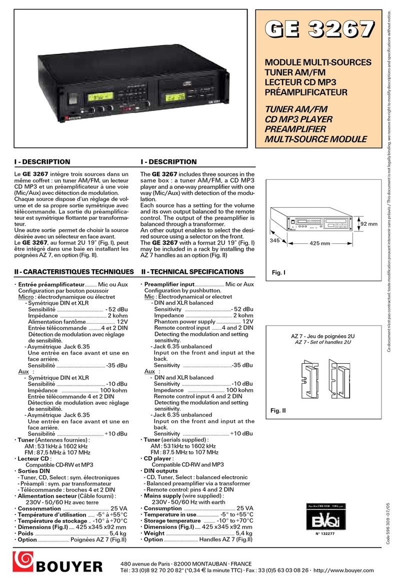
Bouyer GE 3267 User manual

Bouyer
Bouyer SA 3126 User manual
Bouyer
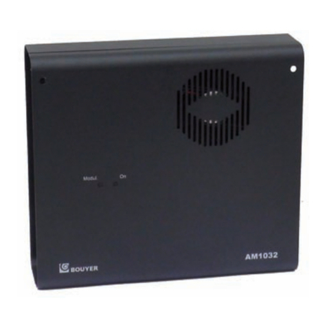
Bouyer AM 1032 I User manual

Bouyer
Bouyer IL 100 User manual
Bouyer
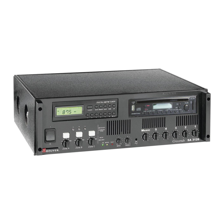
Bouyer Crescendo SA 3126 Instruction manual
Bouyer
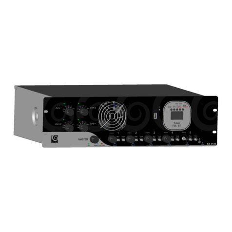
Bouyer SA-3126 Series User manual
Bouyer
Bouyer AS-4000 Series User manual

Bouyer
Bouyer AM-2015-PACK User manual
Bouyer
Bouyer GE 3067 User manual
Bouyer
Bouyer AD1-1075 User manual
Bouyer
Bouyer AS 3066 User manual
Bouyer
Bouyer AP-104 User manual
Bouyer
Bouyer AP 3804 User manual
Bouyer
Bouyer EXCELLENCE Series User manual
Bouyer
Bouyer EXCELLENCE PR 1406 User manual
Bouyer
Bouyer AR 1402 User manual
Bouyer
Bouyer AM-2015 User manual
Bouyer
Bouyer AM-1032 User manual

Bouyer
Bouyer AR 1050 User manual
