Bouyer AM 1032 I User manual
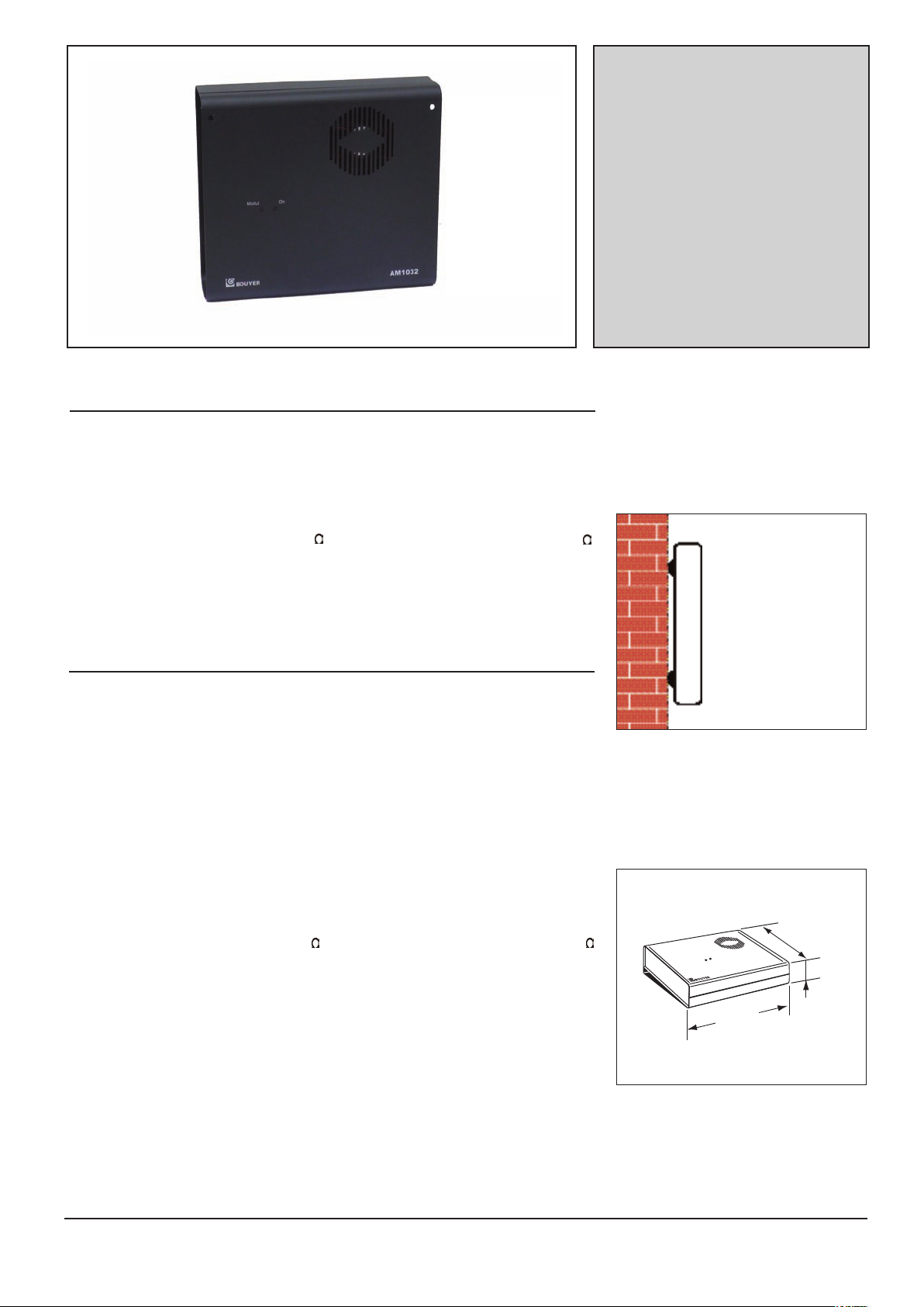
The AM 1032 is a mixer amplifier, dual powe-
red of 30W, with compact dimensions. This
amplifier is designed to be wall mounted.
Two balanced M C inputs with phantom power
supply are available, as well as, 2 unbalanced
AUX inputs. These inputs may be used in
mixing mode or in priority mode.
The loudspeaker output can be either on 4
or 100V line. ts power supply is dual, main-
battery 24V.
• Output power ................................30W RMS
• Distortion ....................< 1% at 30 W - 1 kHz
• Bandwidth ..........................60 Hz - 20000Hz
at 3 dB (AUX)
• Tone controls :
+6dB-5dBat10kHz
+ 4 dB - 10 dB at 100 Hz
• Signal to noise ratio ..........................≥ 75 dB
(input AUX)
• nputs :
Mic 1 bal................................- 60 dB (+0 -5)
Mic 2 bal ..............................- 60 dB (+0 -5)
Aux 1 unbal ..........................- 10 dB (+0 -3)
Aux 2 unbal ..........................- 10 dB (+0 -3)
• Outputs
100V line ..............................................330
Low impedance........................................4
• Power supply
Mains ..................230V 50/60 Hz with earth
Battery....................................................24V
• Consumption
Mains ..................................................90 VA
Battery ....................................................2 A
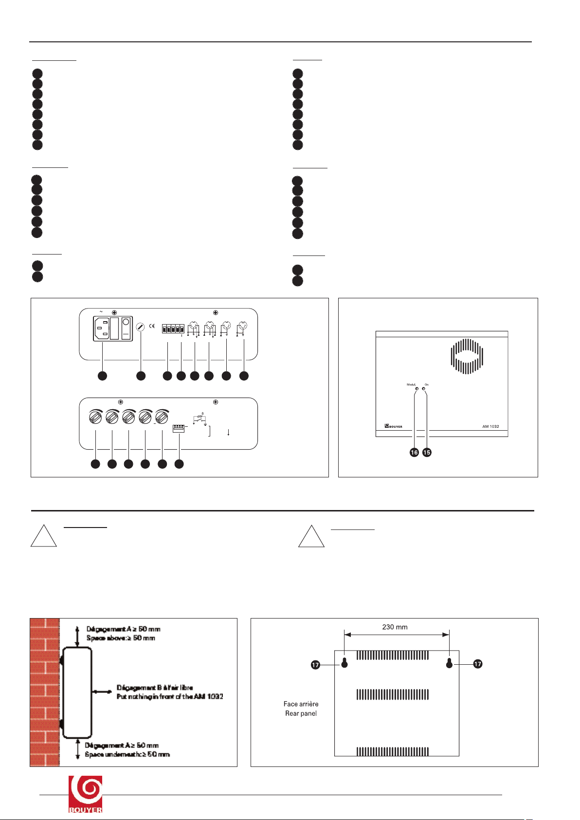
• Dimensions ......................250 x 220 x 70 mm
(WxDxH) (Fig. )
• Weight ............................................ 3,280 kg
• Features
Cooled by fan. Wall fixture with screw.
L’AM 1032 est un amplificateur-mélangeur
mixte 30W de dimensions réduites, destiné à
être fixé sur une paroi.
l possède deux entrées M C symétriques
avec alimentation fantôme et deux entrées
AUX asymétriques. Ces entrées sont gérées
soit en mode mélange soit en mode priorité.
La sortie haut-parleur est disponible en 4
ou en ligne 100V. Son alimentation est mixte,
secteur/batterie 24V.
• Puissance de sortie......................30W RMS
• Distorsion ....................< 1% à 30 W - 1 kHz
• Bande passante ................60 Hz - 20000Hz
à 3 dB (AUX)
• Correcteur de tonalité :
+6dB-5dBà10kHz
+4dB-10dBà100Hz
• Rapport signal/bruit ..........................≥ 75 dB
(entrée AUX)
• Entrées :
Micro 1 sym ..........................- 60 dB (+0 -5)
Micro 2 sym ..........................- 60 dB (+0 -5)
Aux 1 asym ..........................- 10 dB (+0 -3)
Aux 2 asym ..........................- 10 dB (+0 -3)
• Sorties
Ligne 100V..........................................330
Basse impédance ..................................4
• Alimentation
Secteur ................230V 50/60 Hz avec terre
Batterie ..................................................24V
• Consommation
Secteur ..............................................90 VA
Batterie ..................................................2 A
• Dimensions ....................250 x 220 x 70 mm
(LxPxH) (Fig. )
• Poids.............................................. 3,280 kg
• Particularités
Refroidissement par ventilation. Fixation
murale par vis.
AMPL F CATEUR
MÉLANGEUR 30 W
MURAL - Mixte
30 W WALL-MOUN-
TED M XER AMPL -
F ER - Dual
AA
AAMM
MM
11
1100
0033
3322
22
II
II
220 mm
70 mm
250 mm
AM 1032
Modul. On
Ce document n'est pas contractuel; toute modification pouvant intervenir sans préavis / This document is not legally binding, we reserve the right to modify descriptions and specifications without notice.
Code 596 021 - 06/2013
FFiigg.. II
Fixation murale par vis /
Wall fixture with screws
- DESCR PT ON - DESCR PT ON
- CARACTÉR ST QUES TECHN QUES - TECHN CAL SPEC F CAT ONS
ATTENT ON :
The unit is neither water - nor splash proof.
Fix the amplifier so as to allow ventilation by respecting the
empty space shown in Fig. V.
ATTENT ON :
L’appareil ne doit pas être exposé aux chutes d’eau et
aux éclaboussures.
nstaller l’appareil de façon à permettre son refroidisse-
ment (Fig. V).
• Dégagement A ≥ 50 mm
• Dégagement B à l’air libre
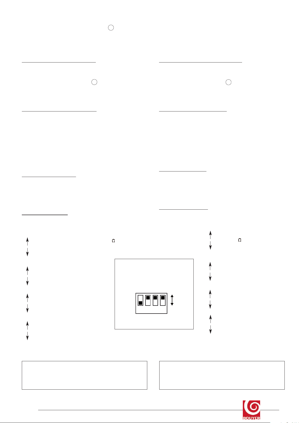
Left side (Fig. )
230V mains plug with switch / earth and mains fuse
Fuse
Loudspeaker output
24 V battery play
M C 1 D N input
M C 2 D N input
AUX 1 D N input
AUX 2 D N input
Right side (Fig. )
Volume control AUX 1
Volume control AUX 2
Volume control M C 2
Volume control M C 1
Tone control
Priority management
Font face ( Fig. )
ON/OFF Led
Modulation Led
Côté gauche (Fig. )
Prise secteur 230V avec interrupteur/ fusible secteur + terre
Fusible basse tension
Sortie HP 0-4 / 0 - 100 V / 330
prise batterie 24 V
Entrée D N Micro 1
Entrée D N Micro 2
Entrée D N Aux 1
Entrée D N Aux 2
Côté droit (Fig. )
Réglage volume Aux 2
Réglage volume Aux 1
Réglage volume Mic 2
Réglage volume Mic 1
Correcteur de tonalité
Gestion des priorités
A l’avant (Fig. )
Voyant de mise sous tension
Témoin de modulation
Côté gauche
Left side
AUX 2 AUX 1 MIC 2 MIC 1 TONE
+
1 2 3 4
1
2 AUX 1/2
3 MIC 2
4 MIC 1
100
PRIORITY
9 10 11 12 13 14
Côté droit
Right side
M IC 1
Télécom .
M IC 2
Télécom .
AUX 1
AUX 2
230V
50/60Hz
Fus.
T 0,4A
2A
SORTIES
OUTPUTS
BATTERY
100V
4
0
+
24 V
13
24 5 6 7 8
FFiigg.. IIII
FFiigg.. IIIIII
FFiigg.. VV
Face avant / Front face
!!
FFiigg.. IIVV
2 AM 1032
- PRESENTAT ON - PRESENTAT ON
1
2
3
4
5
6
7
8
9
10
11
12
13
14
15
16
V - NSTALLAT ON V - NSTALLAT ON
1
2
3
4
5
6
7
8
9
10
11
12
13
14
15
16
Fix 2 screws on a horizontal axis. Distance between 230 mm.
Hook the amplifier onto these screws using the holes.
Screw the 2 screws.
Cables can be connected to the amplifier.
CONNECT ON TO MA N AND 24 V BATTERY
Connect the unit to the 230V mains plug with earth.
For 24 V battery, connect to terminal 4 (Fig. ).
Take care of the polarity + and -, and that the power is switched off
during wiring.
CONNECT ON OF LOUDSPEAKERS
Connect the amplifier output to the loudspeaker line. The 100V output
is often the most convenient. Always ensure that the total loudspeaker
load does not exceed the maximum power of the amplifier (30W).
Check that loudspeaker installed in the same listening area are
connected in phase.
Advice on the choice and orientation of loudspeakers can be found in
the “Sound system handbook”.
MODULAT ON SOURCES
Connect the different modulation sources to the respective D N
inputs following the cabling indication mentionned on the protection
cover.
PR OR TY MANAGEMENT
There several operating modes available, depending on the position
of the micro switches
(Fig. V ).
Put to earth of the point 0 of power
supply by 100
Put to earth of the point 0 of power
supply
AUX 1 + AUX 2 are not submit to
priority
With remote control priority of
M C 1 and M C 2 or AUX 1 + AUX 2
M C 2 does not submit the priority
of M C 1
With remote control priority of
M C 1 or M C 2
Without remote control input 1 is
active
nput 1 is active with remote control
The AM 1032 is delivered following Fig. V
MPORTANT : the remote control is done by pin n°2 + n°4 of the
D N connector. Do not use a lead or modulation source which
may connect pin n°4 to a modulation pin.
Placer dans le mur deux vis sur un axe horizontal, distantes de 230
mm.
Accrocher l’amplificateur sur ces vis par les trous 17 (Fig. V).
Serrer les vis grâce aux trous prévus en face avant.
L’appareil est prévu pour recevoir des câbles encastrés ou appa-
rents.
BRANCHEMENT SECTEUR / BATTER E
Brancher l’appareil à une prise 230V avec terre.
Brancher la batterie 24 V sur le bornier 4 (Fig ).
Attention à la polarité + et - , et s’assurer que les fils sont hors ten-
sion pendant le câblage.
BRANCHEMENT DES HAUT-PARLEURS
Raccorder au mieux la sortie de l’amplificateur et la ligne des haut-par-
leurs. La sortie 100V est souvent la plus pratique.
La somme des puissances attribuées aux haut-parleurs ne doit absolu-
ment pas dépasser la puissance de l’amplificateur (30W).
Vérifier que les haut-parleurs installés dans une même zone d’écoute
sont bien branchés “en phase”
Des précisions sur le choix et l’orientation des haut-parleurs peuvent
être trouvées dans le “Guide de la sonorisation”.
SOURCES DE MODULAT ON
Raccorder les différentes sources de modulation sur les entrées cor-
respondantes aux prises D N suivant le câblage indiqués sur la séri-
graphie du cache de protection.
SYSTÈME DE PR OR TÉ
L’utilisateur à le choix entre plusieurs modes de fonctionnement selon
le positionnement des micro-commutateurs (Fig. V ).
Mise à la terre du zéro d’alimentation par 100
Mise à la terre du zéro d’alimentation
Aux 1 et Aux 2 ne subissent pas
de priorité
Avec télécommande priorité M C 1
et M C 2 sur Aux 1 et Aux 2
M C 2 ne subit pas de priorité du
M C 1
Avec télécommande M C 1 prioritai-
re sur M C 2
Sans télécommande l’entrée 1 est
active
L’entrée 1 est active avec télécommande
L’appareil est livré suivant Fig. V
MPORTANT : la télécommande s’effectuant par l’intermédiaire
des broches n°2 et 4 des prises D N, il y a lieu de ne pas utiliser
de cordon ou de source de modulation qui ramène en contact la
broche n°4 à une broche de modulation.
AM1032 3
1 2 3 4
AUX1 et 2
MIC 2
MIC 1
FFiigg.. VVII
1
2
3
4
1
2
3
4
Avant la mise sous tension, placer chaque bouton en position “0”
Mettre l’appareil sous tension et vérifier que le témoin d’alimentation
15 (Fig. ) fonctionne. Éviter l’effet «Larsen» en cas d’utilisation
d’un microphone. Ajuster soigneusement les réglages des entrées et
du correcteur de tonalité.
En cas de panne :
Vérifier l’état des fusibles et les remplacer si besoin par des
fusibles de mêmes caractéristiques tel qu’indiqué sur
l’appareil.
Attendre que l’appareil refroidisse pour s’assurer que la
panne n’est pas due à la protection thermique.
Sinon retourner l’appareil à l’usine, ou faire appel à un
dépanneur professionnel.
n case of failure :
Check the status of the fuses and replace them if needed
by fuses with the same caracteristics as those indicated
on the product.
Wait until the product has cooled off, to be sure that the
failure is not caused by the thermal relay.
Otherwise the product has to be sent back to the factory
or repaired by a recognised dealer.
!!•
•
•
•
•
•
4AM 1032
V - UT L SAT ON V - USE
V - MA NTENANCE V - MA NTENANCE
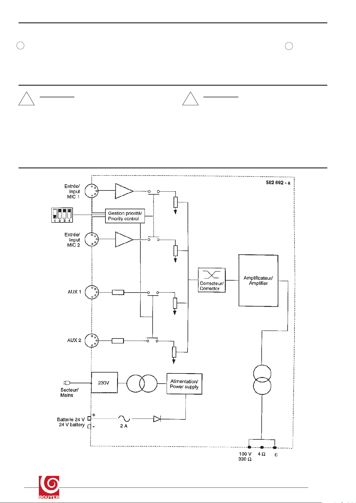
V - SCHÉMA SYNOPT QUE V - SCHEMAT C
Before putting ON, put each control button on “0”
Put ON and check that the ON/OFF Led is active 15 (Fig. )
Avoid «feedback» in case of microphone use.
Carefully adjust volume and tone controls.
Other Bouyer Amplifier manuals

Bouyer
Bouyer SA-1127 User manual

Bouyer
Bouyer EB 134 User manual

Bouyer
Bouyer GE 3067 User manual

Bouyer
Bouyer IL 100 User manual

Bouyer
Bouyer GE 3267 User manual

Bouyer
Bouyer AM-2015-PACK User manual

Bouyer
Bouyer AP-104 User manual

Bouyer
Bouyer SA-3126 Series User manual

Bouyer
Bouyer EXCELLENCE PR 1406 User manual

Bouyer
Bouyer AR 1050 User manual

Bouyer
Bouyer SA 3126 User manual

Bouyer
Bouyer AP 3804 User manual

Bouyer
Bouyer Crescendo SA 3126 Instruction manual

Bouyer
Bouyer AD1-1075 User manual

Bouyer
Bouyer EXCELLENCE Series User manual

Bouyer
Bouyer AS 3066 User manual

Bouyer
Bouyer AM-1032 User manual

Bouyer
Bouyer AS-4000 Series User manual

Bouyer
Bouyer AR 1402 User manual

Bouyer
Bouyer AM-2015 User manual


