BOWHEAD REACH User manual

The REACH
Electric Bike User Manual
bowheadcorp.com

1 | P a g e
Table of Contents
1 GENERAL....................................................................................................................................................2
1.1 Use of the manual ..............................................................................................................................2
1.2 Service and technical support............................................................................................................2
1.3 Initial Checks Before Use....................................................................................................................2
1.4 Product Information and Specifications............................................................................................3
1.5 Diagram of General Bike Components ..............................................................................................4
2 SAFETY .......................................................................................................................................................5
2.1 Battery and Charger...........................................................................................................................5
2.2 Bike Usage ..........................................................................................................................................5
2.3 Rear Push Handle Usage ....................................................................................................................6
2.4 Transportation and Riding .................................................................................................................6
2.5 Leg Strap Information ........................................................................................................................7
3 BATTERY OVER VIEW.................................................................................................................................8
3.1 General Remarks................................................................................................................................8
3.2 Removal of Battery ............................................................................................................................9
3.3 Charging the Battery ........................................................................................................................11
3.4 Storage..............................................................................................................................................11
3.5 Battery: Further Information...........................................................................................................12
4 BIKE USAGE..............................................................................................................................................13
4.1 Maintenance.....................................................................................................................................13
4.1.1 Torque Chart –Metric and Imperial.........................................................................................14
4.2 Range ................................................................................................................................................15
4.3 Seat Plate Adjustment .....................................................................................................................16
4.4 Foot Rest Adjustment ......................................................................................................................17
4.5 Mounting Accessories ......................................................................................................................18
4.6 Articulation Locking Pin Removal and Storage ...............................................................................19
4.7 Adjustable Screw Callout .................................................................................................................20
5 TROUBLESHOOTING ................................................................................................................................21
6 FREQUENTLY ASKED QUESTIONS............................................................................................................22

2 | P a g e
1 GENERAL
1.1 Use of the manual
Read this manual carefully before you start riding on your new Bowhead Reach. Safety
instructions are very important and should not be overlooked. By doing so you will have a
better understanding of the general operation of the bike and various bike parts. Some
frequently asked questions and troubleshooting methods will be covered as well. Legal
documentation, such as warranty, is included in this manual at your service. So, take a moment
to read this manual before you start riding.
1.2 Service and technical support
This manual is not intended to be an extensive reference book about service, maintenance
and/or repairs. Please consult your dealer for service and technical support. You can find more
information about our products via our website(www.bowheadcorp.com) and various guided
maintenance videos on our YouTube Channel
(https://www.youtube.com/channel/UCqZii12qtvKGZOnqSHkXGQg).
IMPORTANT NOTICE
•Contact the place of purchase for information on installation and adjustment of the
products which are not found in the user's manual.
•Do not disassemble or alter this product.
•Use the product according to local laws and regulations.
For safety, be sure to read this user's manual thoroughly before use, and follow them for
correct use.
1.3 Initial Checks Before Use
➢Is the battery fully charged?
➢Is the tire pressure adequate for usage? Refer to tire for manufacturer recommended
pressure inflation.
➢Are the brakes operating correctly?
➢Are all adjustable screws securely tightened? Refer to Figures A and B on Page 19 of
this manual.
➢Are the shocks pumped to the correct pressure? Refer to the shock User Manual to set
appropriate pressure.

3 | P a g e
1.4 Product Information and Specifications
Bike Specifications
Model
The REACH
Overall Length and
Width
80 in
26.5 in
Front Wheel Diameter
20 in (406 ERD)
Rear Wheel Diameter
26 in (559 ERD)
Max Speed
33 km/h
Range Per Charge
25-30 km (80V)
50-60 km (140V)
Weight
96 lbs
Turning Radius
80 in
Wheelbase
49 in
Front Suspension Travel
3 in
Rear Suspension Travel
7.5 in
Battery
Rated Voltage
Standard: 80V
X-Lrg: 140V
Capacity
Standard: 15 Ah
X-Lrg: 21 Ah
Charging Time
~5 hours
4 | P a g e
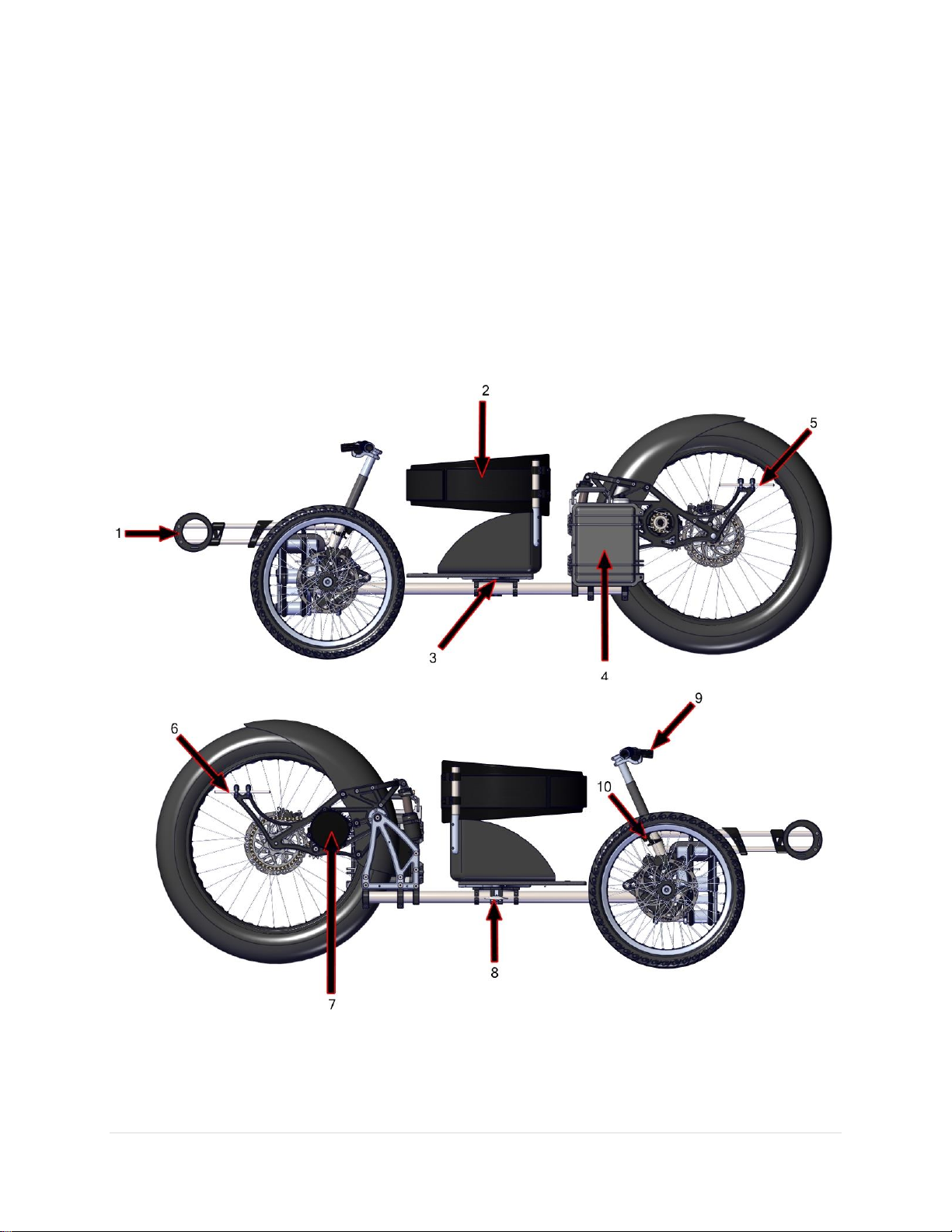
1.5 Diagram of General Bike Components
1
Adjustable Foot Rest
6
Right side Accessory Mount
2
Harness
7
Motor
3
Seat Plate
8
Swivel Seat Lever
4
Battery
9
Brake and Throttle Controls
5
Left side Accessory Mount
10
Articulation Pin Storage Holder

5 | P a g e
2 SAFETY
2.1 Battery and Charger
•Keep the battery & charger away from water and open fire.
•Do not use the battery & charger for other purposes.
•Do not connect positive and negative terminals.
•Keep the battery away from children and pets.
•Do not subject the battery & charger to shocks (e.g. by dropping).
•Do not cover the battery & charger or place objects on top of it.
•Stop the charging procedure immediately if you notice a strange smell or smoke.
•Do not deform, modify, disassemble or apply solder directly to the battery. Doing so
may cause leakage, overheating, bursting, or ignition of the battery.
•In the unlikely case that the battery is on fire, do NOT try to put it out with water. Use
sand instead and call emergency services immediately.
2.2 Bike Usage
Before using the Reach on the open road, ride the bike in a secure area to get acquainted with
riding this bike. Try all settings and differing terrain on the bike and get familiar with the results.
•Be sure to remove the battery and charging cable before wiring or attaching parts to the
bicycle. Otherwise, an electric shock may result.
•When charging the battery while it is installed on the bicycle, do not move the bicycle.
The power plug for the battery charger may come loose and not be fully inserted into
the electrical outlet, resulting in risk of fire.
•If bolts and nuts are left loosened or the product is damaged, the bicycle may suddenly
fall over and serious injury may result.
•Do not disassemble the product. Disassembling it may cause injury to persons.
•After reading the user's manual carefully, keep it in a safe place for later reference.
IMPORTANT NOTICE
The following section regarding usage of the rear push handle must be read and all safety
procedures should be followed to avoid rider, or any other injury.
6 | P a g e
2.3 Rear Push Handle Usage
➢The rear push handle is mounted to the rear swing arm and is equipped with a separate
throttle and brake system. When the rear drive system is engaged the rider will only be
able to supply steering input.
➢The individual pushing the bike MUST be secured to the push handle via the waist and
wrist strap at ALL times when the bike is powered on.
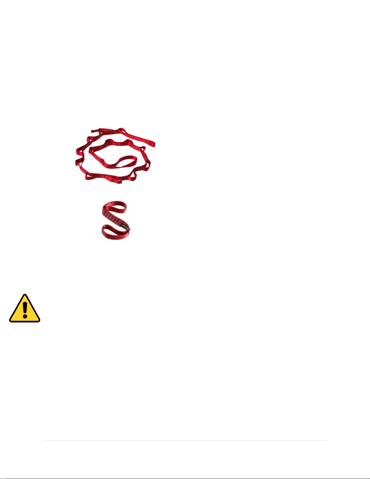
To attach the waist strap:
-Grab the free cord end and wrap it
around your waist at approximately
belly button level
-Secure the cord end by clipping the
carabiner to a loop on the chain at a
comfortable position
To attach the wrist strap:
-Slide the wrist strap over your hand
and around your wrist and twist it
around 2-3 times to fasten it
2.4 Transportation and Riding
IMPORTANT NOTICE
All riders MUST wear a helmet and leg straps at ALL TIMES when operating the Bowhead Reach.
A step by step demonstration of leg strap usage is outlined in section 2.5 following.
Batteries are not designed to be on the bike during transportation by car. Batteries must be
taken off the bike(s) and transported separately inside the car. Battery removal steps will be
covered in section 3.2 of this manual.
•The Bowhead Reach is not a street legal vehicle
•Riders MUST obey all posted speed limits and signage
•Not designed for downhill racing
•Not designed for any jumps including ramps or voids
7 | P a g e
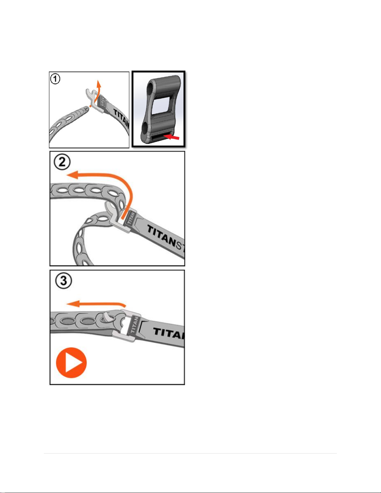
2.5 Leg Strap Information
Ensure the logo is facing outward and
thread through the slot in the plastic foot
rest spacer.
Thread the end around both of your legs
and then through the buckle.
Stretch and secure the strap over flange.
The tension in the strap is what secures it
in place.
8 | P a g e
3 BATTERY OVER VIEW
3.1 General Remarks
• Stop the charging procedure immediately if you notice a strange smell or smoke. Call the
dealer for service or replacement.
• In the unlikely case that the battery is on fire, do NOT try to put it out with water. Use sand
instead to cover the fire and call emergency services as soon as possible.
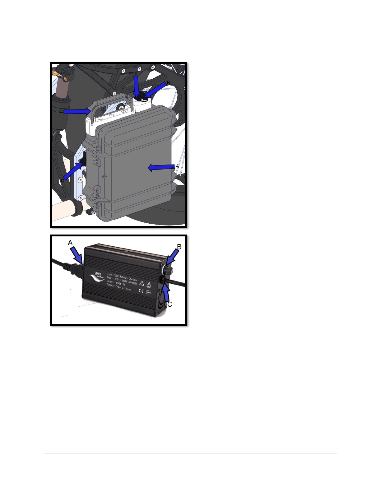
A-Battery
B-Charging plug
C-Handle
D-Magnetic self-locking tab
E-Power socket
A- Power cord
B- Fuse
C- Power Supply to Battery
9 | P a g e
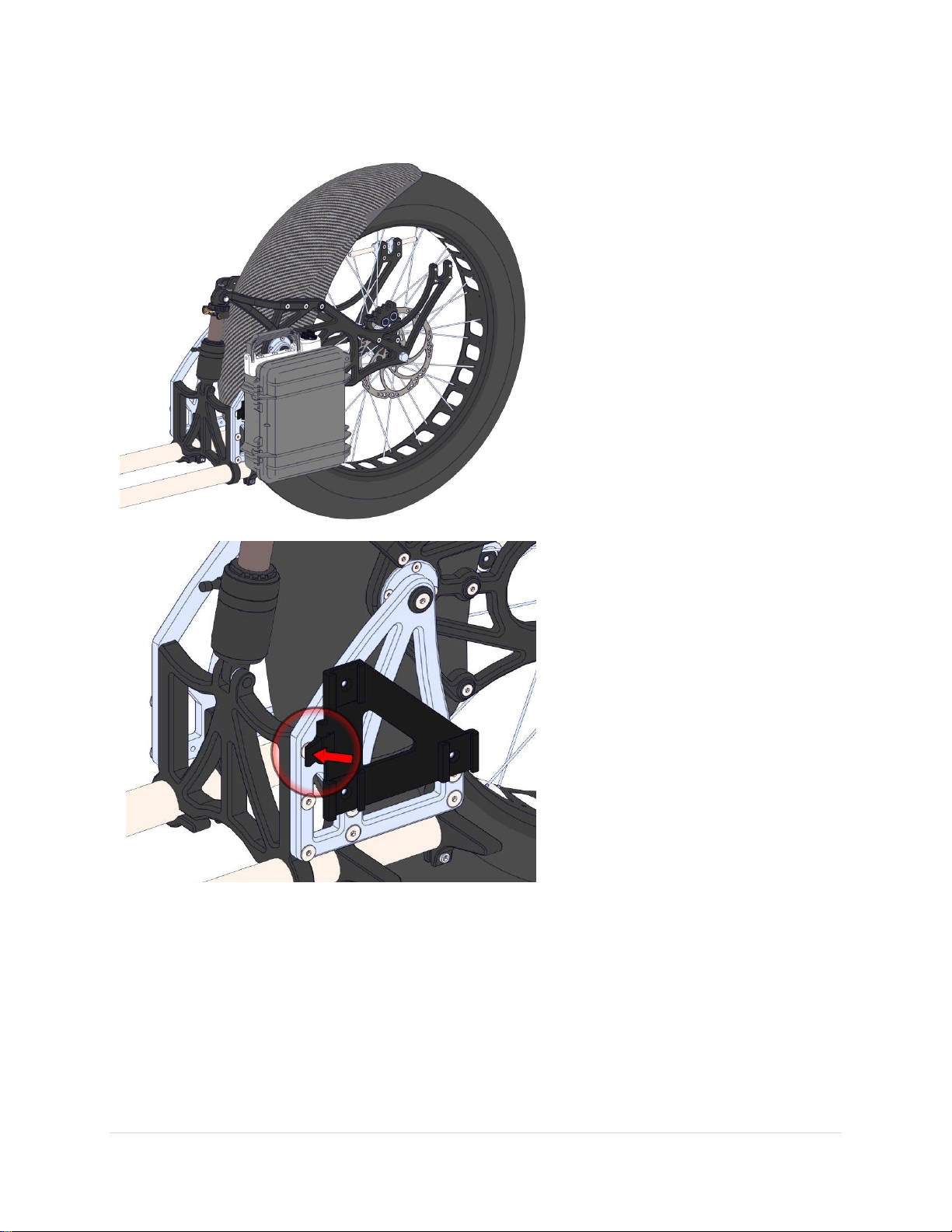
3.2 Removal of Battery
The battery is locked in place via
a secure magnetic locking system
under typical operating
conditions.
User input is required to remove
the system and recharge the
battery.
To remove the battery:
i. Press down (the direction
indicated by the red arrow
in the diagram) on the
self-locking tab
10 | P a g e
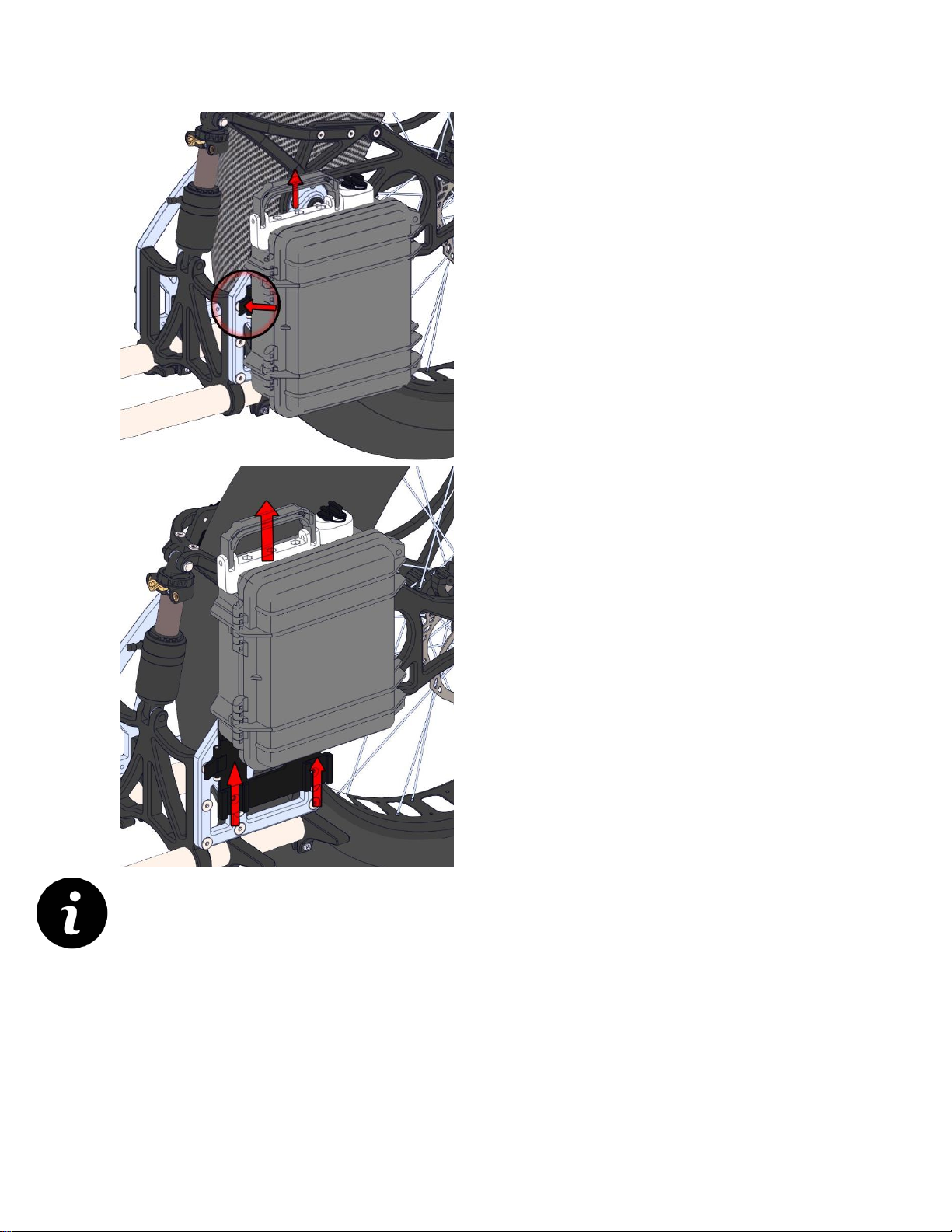
ii. While pressing down on the self-
locking tab, grab the handle
mounted on the top of the battery
case and pull upwards.
iii. Once the case begins to move
along the case slots it is no longer
necessary to manually engage the
tab. The battery will slide up and
out of the slots.
NOTE:
Please ensure to fully charge the battery if you are planning to ride your bike in the next 30
days AND leave it charging for at least 1 hour once a full charge is achieved. (This allows the
Battery Management System to completely balance the individual cells inside the battery
ensuring longevity and proper functioning of your battery.)
➢If you are not planning on riding the bike in 30 days, the battery should be charged to
approximately 80%. At this point the battery is safe for storage.

11 | P a g e
3.3 Charging the Battery
Charging the battery should be at room temperature (±20°C/68°F). Charging below 0°C or
above 40°C (32°F~104 °F) can lead to insufficient charging and can be harmful to the battery life
cycle.
Charger
• Not connected: Charger LED is green (constant).
• During charging: Charger LED is red (constant)
• Charging issue: Charger LED is red (blinking)
• Charging is completed (100%): Charger LED is green (constant)
Charger time table (Standard Size Battery)
Charge time in kilometers
15 Ah
80% Charge
15-20 km
100% Charge
25-30 km
Charger time table (XL Size Battery)
Charge time in kilometers
21 Ah
80% Charge
40-45 km
100% Charge
50-60 km
NOTE: When the battery is first received, please ensure you charge it for a minimum of 7 hours
➢The battery takes approximately 5 hours to fully charge
3.4 Storage
If the bike is not used for a longer period (one month or more) the battery is best stored:
•At 80% of its capacity.
•Separate from the bike.
•At temperatures between 0°C and 40°C.
•In a safe and dry location.
•Checked every month. Charge when needed. Charging the battery should be done at a
minimum of every 3 months. Negligence to do this could void the warranty of the battery.

12 | P a g e
3.5 Battery: Further Information
➢Do not expose battery or charger to wet, rainy, or extremely humid conditions
➢If battery or controller are exposed to moisture (from rain or washing your bike) you
must open both cases and allow the internal components to completely dry before
usage
➢Only use the designated charger supplied with the battery

13 | P a g e
4 BIKE USAGE
4.1 Maintenance
Do not use high-pressure water or air hoses for cleaning. It can force water into electric
components, which may cause malfunctioning.
Do not wash plastic components with excessive water. When the internal electrical parts are
infected with water, the insulator may corrode which leads to power-drain or other problems.
Do not use soap solutions to wash the plastic components. Non-neutral solutions may cause
color change, distortion, scratching etcetera.
Avoid leaving the bike outdoors.
When not riding, keep the bike in a location where it will be protected from snow, rain, sun etc.
Snow and rain can cause the bike to corrode. The ultraviolet from the sun can fade the paint or
crack any rubber or plastic on the bike. The carbon and anodized aluminium will fade if left out
exposed to the sun.
NOTE: The following maintenance checks should be performed after the first 5 rides and again
after every 15 rides or 6 months, whichever measurable occurs first.
➢Check the M6 Socket head cap screws (6) on the rear frame clamp to ensure they are
sufficiently tight (7.8 Nm or 5.75 lbft torque)
➢Check the M8 socket countersunk head screws (16) on the rear system mount to ensure
they are sufficiently tight (19.1 Nm or 14.09 lbft torque)
➢Check all screws involved in the seat plate adjustment and footrest adjustment to
ensure they are sufficiently tight
➢Check the M8 flat head screws (6) on the front of the articulation to ensure they are
sufficiently tight (19.1 Nm or 14.09 lbft torque)
➢Check the tire pressure of all wheels referring to the manufacturer specifications on the
side of the tire to ensure adequate levels for your riding environment
➢Check shock pressure referring to the shock User Manual provided with the bike to
achieve accurate levels
IMPORTANT NOTICE
A full torque chart and specs in metric and imperial units may be found on the following page.
DO NOT exceed the specified torque value as this may damage the bike and void warranty.

14 | P a g e
4.1.1 Torque Chart –Metric and Imperial
Torque Chart
Size of Screw
Required Torque (Nm)
Required Torque (lbft)
M5
5.1
3.76
M6
7.8
5.75
M8
19.1
14.09

15 | P a g e
4.2 Range
The range on one charge strongly depends on several circumstances, such as (but not limited
to):
• Weather conditions such as ambient temperature and wind;
• Road conditions such as elevation and road surface;
• Bike conditions such as tire pressure and maintenance level;
• Bike usage such as acceleration;
• Rider and luggage weight;
• Charge and discharge cycles.

16 | P a g e
4.3 Seat Plate Adjustment
The seat is adjustable to slide along
the frame rails to accommodate
various user height requirements.
It is secured in place by 6 M5 socket
head cap screws.
To move the seat plate:
i. The 6 screws located on the
bottom of the rail mount
must be loosened.
A 5 mm Allen Key should be used in
the direction depicted in the figure
on the left to loosen these screws.
ii. The entire seat assembly may
now be slid forward and
backward to reach a
comfortable position.
iii. After locating the seat in the
appropriate position, the 6
screws must be tightened (4.6
Nm or 3.39 lbft torque) to
secure the seat in its’ new
location.

17 | P a g e
4.4 Foot Rest Adjustment
Similar to the seat, the footrest may
also be adjusted to an appropriate
length for each individual user.
It is secured in place by 2 M6 socket
head cap screws.
To move the footrest:
i. The 2 screws located on the
left side of the footrest frame
must be loosened.
A 6 mm Allen Key should be used
in the direction depicted in the
figure to loosen/remove these
screws.
ii. The footrest may now be slid
forward or backward to
lengthen or shorten this
distance.
iii. Once the footrest is in a
comfortable location for riding
the 2 screws must be tightened
(7.8 Nm or 5.75 lbft torque) to
secure the new position.

18 | P a g e
4.5 Mounting Accessories
The rails installed on either side of the
swing arm can be used to mount
various accessories such as panier
bags.
19 | P a g e
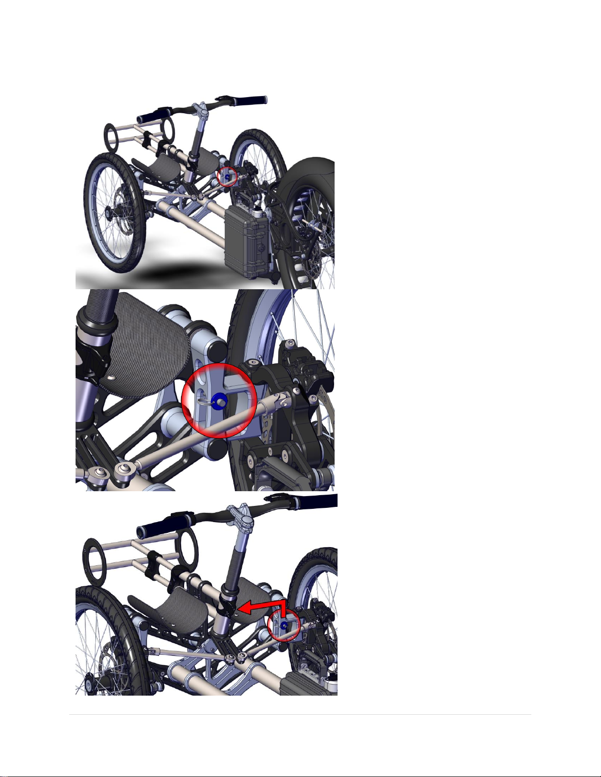
4.6 Articulation Locking Pin Removal and Storage
The pin highlighted by the red
circle as seen in the figure locks
any articulation movement of the
bike.
This pin MUST be removed
before riding the bike.
To remove the pin:
i. Press down on the pin and
pull the pin from its slot
ensuring you have a firm
grip on the seat or harness
so the bike will not fall
once the pin is removed.
To store the pin:
ii. The pin should be stored in
the mount shown in the
figure on the left. The top
of the pin must be pressed
down in order to insert the
pin in this storage mount.
iii. After riding, the pin should
be put back in the original
location to lock
articulation movement
once again.
Other manuals for REACH
2
Table of contents
Other BOWHEAD Scooter manuals


