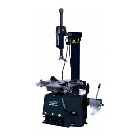
BOXER KING 5600 User manual

Service Manual 04/2010 Rev.B
1
Author Stefano Muzzioli
BOXER KING 5600/5600R
TRUCK TYRE CHANGER
SERVICE MANUAL

Service Manual 04/2010 Rev.B
2
UPDATING GUIDE:
Release Bof 02/04/2010
Removed “50 or 60 Hz” At page 49

Service Manual 04/2010 Rev.B
3
TABLE OF CONTENTS
1.0 Introduction Pag. 5
2.0 Tools and special tools required Pag. 5
2.1 Use of digital multimeter Pag. 8
3.0 Diagrams section: electric and hydraulics Pag. 8
3.1 Electric diagram for CE proved King 5600 Pag. 9
3.2 Electric diagram for King 5600 supplied at 200/3/60 Pag. 17
3.3 Electric diagram for CE approved King 5600R Pag. 25
3.4 Electric diagram for King 5600R supplied at 200/3/60 Pag. 33
3.5 Hydraulic diagram for CE approved King 5600 Pag. 41
3.6 Hydraulic diagram for non CE approved King 5600 Pag. 43
3.7 Hydraulic diagram for CE approved King 5600R Pag. 45
3.8 Hydraulic diagram for non CE approved King 5600 R Pag. 47
4.0 Electric function Pag. 49
5.0 Access to electric parts Pag. 50
5.1 Power supply cable and plug: check and replacement Pag. 51
5.2 Main switch Q1: check and replacement Pag. 52
5.3 Circuit Breaker Q2: check and replacement Pag. 53
5.4 Hydraulic motor cable: check and replacement Pag. 54
5.5 Hydraulic motor: check and replacement Pag. 54
5.6 Fuses F1,F2,F3: check and replacement Pag. 56
5.7 Inverter pole switch Q3: check and replacement Pag. 57
5.8 Chuck motor cables: check and replacement Pag. 58
5.9 Chuck motor: check and replacement Pag. 58
5.10 Transformer: check and replacement Pag. 61
5.11 Fuses F4,F5,F6,F7: check and replacement Pag. 61
5.12 Link converter: check and replacement Pag. 62
5.13 Three polar meters K1,K2: check and replacement Pag. 62
5.14 Portable control cable: check and replacement Pag. 63
5.15 Switches S1: check and replacement Pag. 66
5.16 Micro switches S2, S3, and S6: check and replacement Pag. 66
5.17 Micro switches S2, S3 and S6 holders: check and replacement Pag. 66
5.18 Shut off cable: check and replacement Pag. 67
5.19 Shut off switch S4: check and replacement Pag. 68
5.20 Emergency switch S5: check and replacement Pag. 69
5.21 Robotic safety switch cable: check and replacement Pag. 70
5.22 Robotic safety switch: check and replacement Pag. 72
5.23 Coil connector cable: check and replacement Pag. 72
6.0 Hydraulic function Pag. 73
6.1 Access to hydraulic parts Pag. 75
6.2 Hydraulic oil level: check and levelling Pag. 78
6.3 High hydraulic pressure circuit: check and adjustment Pag. 79
6.4 Low hydraulic pressure circuit: check and adjustment Pag. 79
6.5 Hydraulic pressure of chuck cylinder: check and adjustment Pag. 80
6.6 Saddle cylinder sliding hydraulic pressure: check and adjustment Pag. 83
6.7 Hydraulic pump: check and replacement Pag. 85
6.8 Coil valve: check and replacement Pag. 87
6.9 King 5600 saddle cylinder: check and replacement Pag. 88
6.10 King 5600R saddle cylinder: check and replacement Pag. 90
6.11 King 5600 saddle cylinder seals: check and replacement Pag. 92
6.12 King 5600R saddle cylinder seals: check and replacement Pag. 94
6.13 Chuck arm cylinder: check and replacement Pag. 94
6.14 Chuck arm lowering speed: check and adjustment Pag. 95
6.15 Chuck arm cylinder seals: check and replacement Pag. 96
6.16 Chuck cylinder: check and repairing Pag. 96

Service Manual 04/2010 Rev.B
4
6.17 Tool holder cylinder: check and replacement Pag. 99
6.18 Tool holder cylinder seals: check and replacement Pag. 100
6.19 King 5600R robotic cylinder: check and replacement Pag. 101
6.20 King 5600R robotic cylinder seals: check and replacement Pag. 104
7.0 Mechanical section Pag. 104
7.1 Saddle: check and adjustment Pag. 104
7.2 King 5600R saddle slides: check and replacement Pag. 105
7.3 King 5600 saddle slides: check and replacement Pag. 108
7.4 King 5600 saddle bushings: check and replacement Pag. 109
7.5 King 5600R robotic rotation: check and adjustment Pag. 109
7.6 King 5600R robotic rotor: check and replacement Pag. 110
7.7 King 5600R lower robotic cam and spring: check and replacement Pag. 112
7.8 King 5600R tool holder moving cabinet: check and replacement Pag. 115
7.9 Shutdown pin: check and replacement Pag. 116
7.10 King 5600R tool holder arm bushings: check and replacement Pag. 117
7.11 King 5600R hook:check and adjustment Pag. 117
7.12 King 5600R hook:check and replacement Pag. 118
7.13 King 5600 hook:check and adjustment Pag. 118
7.14 King 5600 hook:check and replacement Pag. 119
7.15 Screw support tool: check and adjustment Pag. 120
7.16 King 5600 tool holder arm: check and replacement Pag. 120
7.17 King 5600R tool holder arm: check and replacement Pag. 121
7.18 Mount - Dismount tool: check and replacement Pag. 122
7.19 Jaws and claws: check and replacement Pag. 123
7.20 Worm screw: check and replacement Pag. 124
7.21 Worm screw seal: check and replacement Pag. 126
7.22 Chuck seal: check and replacement Pag. 127
8.0 Trouble shooting Pag. 128
9.0 Service Bulletins Pag. 130

Service Manual 04/2010 Rev.B
5
1.0 INTRODUCTION
This technical manual describes maintenance,
check and repair operations of the G.S. range of
Boxer King 5600 and 5600R and is for use of
qualified personnel only.
This manual is also applicable to the following
models:
BOXER KING 5600/5600R
ACCU 4560/4560MR
HOFMANN JAPAN GX56
HOFMANN MONTY 4400/4400R
TIP TOP PROMONT 956 SUPER
EIWA WING 311
COATS 9500/9500R
Reproduction, translation and accommodation
rights are reserved.
ALL SAFETY REGULATIONS
MUST BE STRICTLY
FOLLOWED DURING ANY
MAINTENANCE, CHECK AND
REPAIR OPERATION.
PERSONNEL PERFORMING
MAINTENANCE, CHECK AND
REPAIR OPERATIONS MUST
HAVE BEEN DULY TRAINED BY
G.S. AUTHORIZED
INSTRUCTORS.
Keep this manual constantly updated, by adding
Service Bulletins related to Boxer King 2600.
IMPORTANT!
THE IDENTIFICATION DATAS OF EACH
MACHINE ARE PRINTED ON A PLATE.
UNTILL DECEMBER 31 2001, THE SERIAL
NUMBER IS A SEQUENCE OF FIGURES
STANDING FOR THE MANUFACTURING
MONTH (#1) AND YEAR (#2), FOLLOWED BY A
PROGRESSIVE NUMBER (#3) AND #4 SHOWS
THE MODEL.
STARTING FROM JANUARY 1 2002, THE
SERIAL NUMBER HAS CHANGED SEQUENCE
OF FIGURES STANDING FOR THE
MANUFACTURING MONTH (#1) AND YEAR
(#2), REFERENCE NUMBER OF THE MACHINE
(#3) AND PROGRESSIVE NUMBER OF THE
MACHINE (#5) MANUFACTURED WITH THIS
PART NUMBER.
THE #4 STILL SHOWS THE MODEL.
2.0 TOOLS
Before starting any repair operation, make sure
that all required tools are available:
1 Set of end wrenches from 8 to 30mm
Fig.1
1 Set of screwdrivers (standard and cross type).
Fig.2

Service Manual 04/2010 Rev.B
6
1 Set of tube type wrenches from 7 to 13mm.
Fig.3
1 Set of Allen wrenches from 3 to 12mm.
Fig.4
1 Set of socket wrenches of 17-19-22-24mm and
Allen socket wrench of 10 and 12mm
Fig.5
Dyanamometric wrench.
Fig.6
Standard pliers, Seeger pliers and scissor.
Fig.7
Rubber and steel hammers.
Fig.8
Extractor
Fig.9

Service Manual 04/2010 Rev.B
7
1 Tool for removal of cylinder pin # 4013567
Fig.10
1 Multimeter, Loctite green type, Silicon
Fig.11
1 Ammeter pliers
Fig.12
In addition to a standard set of hand tools, the
following special tools are required:
1 Wrench adjustment of saddle clearance #
0013564.
Fig.13
1 Manometer with adapter # 4006849.
Fig.14
2 Calliper wrenches of 5 and 6mm to open the
cylinders.
Fig.15
Spanner wrench

Service Manual 04/2010 Rev.B
8
2.1 USE OF DIGITAL MULTIMETER
In this manual it is frequently required the use
of a digital multimeter.
We recommend a digital multimeter instead of
an analog model because easier to use and
more accurate.
CAREFULLY READ THE
INSTRUCTION MANUAL OF
YOUR MULTIMETER FOR
EVERY INFORMATION
CONCERNING ITS FUNCTIONS.
The following short notes are just to remind
some important general principles.
ALL SAFETY CAUTIONS MUST
BE RESPECTED FOR A
CORRECT USE OF
MEASUREMENT DEVICES.
NEVER APPLY TO YOUR
MULTIMETER CURRENT OR
VOLTAGE HIGHER THAN
MULTIMETER MEASUREMENT
CAPACITY.
PAY EXTRA CARE WHEN
MEASURING VOLTAGE
BEYOND 50 VOLTS.
WHENEVER POSSIBLE
DISCONNECT POWER SUPPLY
CIRCUIT BEFORE
CONNECTING MULTIMETER
TERMINALS TO THE
CONTACTS.
To measure VDC values (direct current):
•Suitably adjust the end of scale selector and
VDC selector . If you don't know the probable
value of the voltage to measure, start with the
highest end-of-scale value.
•Connect the terminals as per instructions.
If - - - is displaied and the terminals are
connected as per instructions, the polarity is
reversed.
To measure VAC values (alternate current):
•Suitably adjust the end of scale selector and
VAC selector . If you don't know the probable
value of the voltage to measure, start with the
highest end-of-scale value.
•Connect the terminals as per instructions.
To measure current magnitude (AC-DC):
•Disconnect power supply.
•To measure the current intensity, the
multimeter must be connected in series with
the circuit.
•Suitably adjust the end of scale selector and
Amp selector . If you don't know the probable
value of the voltage to measure, start with the
highest end-of-scale value.
•If - - - is displaied and the terminals are
connected as per instructions, the polarity (DC)
is reversed.
To measure resistance (Ohm) values:
•Disconnect the component to be tested from
the rest of the circuit.
•Suitably adjust the end of scale selector
and Ωselector . If you don't know the
probable value of the voltage to measure,
start with the highest end-of-scale value.
3.0 DIAGRAM SECTION: ELECTRIC
AND HYDRAULIC
The differences between the King 5600 diagrams
and the 5600R ones consist in the robotic tool
movement only.
The electric diagram includes two more switches
while the hydraulic one includes one more coil
valve and one more cylinder.

Service Manual 04/2010 Rev.B
9
3.1 ELECTRIC DIAGRAM FOR CE PROVED KING 5600
Fig.16

Service Manual 04/2010 Rev.B
10
Fig.17

Service Manual 04/2010 Rev.B
11
Fig.18

Service Manual 04/2010 Rev.B
12
Fig.19

Service Manual 04/2010 Rev.B
13
Fig.20

Service Manual 04/2010 Rev.B
14
Fig.21

Service Manual 04/2010 Rev.B
15
Fig.22

Service Manual 04/2010 Rev.B
16
Fig.23

Service Manual 04/2010 Rev.B
17
3.2 ELECTRIC DIAGRAM FOR KING SUPPLIED AT 200V-3PH-60Hz
Fig.24

Service Manual 04/2010 Rev.B
18
Fig.25

Service Manual 04/2010 Rev.B
19
Fig.26

Service Manual 04/2010 Rev.B
20
Fig.27
This manual suits for next models
1
Table of contents
Other BOXER Tyre Changer manuals
Popular Tyre Changer manuals by other brands

Hofmann
Hofmann monty 3550 Operation instructions, Spare parts list
Hunter
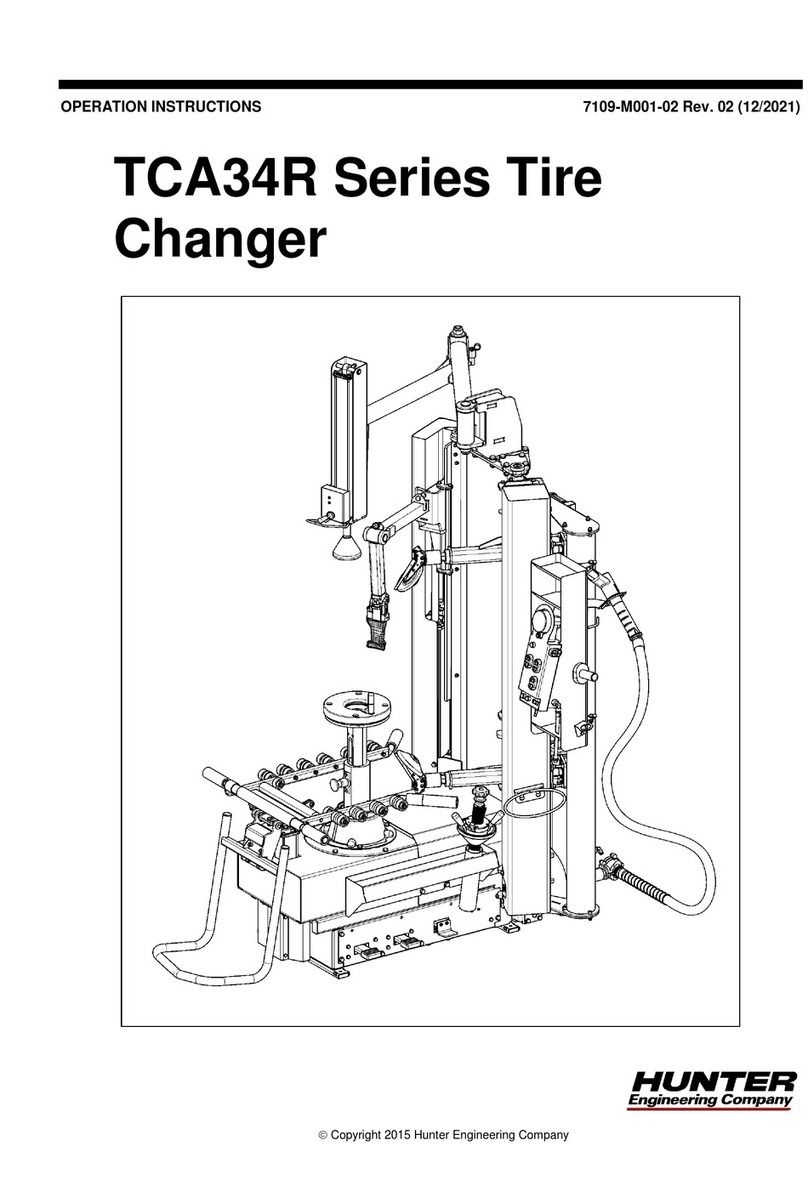
Hunter TCA34R Series Operation instructions
Ranger
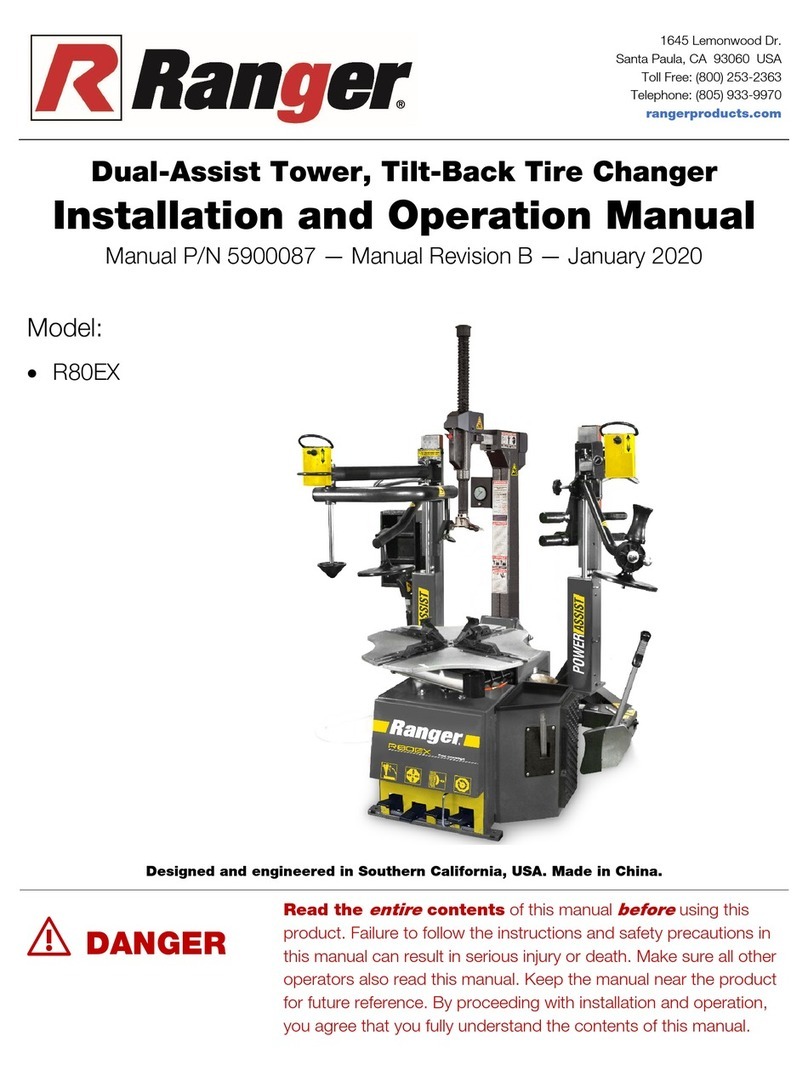
Ranger R80EX Installation and operation manual

pela tools
pela tools U-2011 manual

Glomstad Motor
Glomstad Motor GM-U221 PRO Use and maintenance manual

Corghi
Corghi HD 900 Operator's manual
