Hunter TCA34R Series User manual

Copyright 2015 Hunter Engineering Company
OPERATION INSTRUCTIONS 7109-M001-02 Rev. 02 (12/2021)
TCA34R Series Tire
Changer

OWNER INFORMATION
Model Number _____________________________________________________________________
Serial Number _____________________________________________________________________
Date Installed______________________________________________________________________
Service and Parts Representative ______________________________________________________
Phone Number_____________________________________________________________________
Sales Representative________________________________________________________________
Phone Number_____________________________________________________________________
Concept and Procedure Explanation
Safety Precautions Trained Declined
Warning and Caution Labels
Bead Roller
Maintenance and Performance Checks Trained Declined
Air Pressure Check
Checking Arm Calibration to Rims
Adjustment and Filling of Oiler
Oil Type/Lubrication Fittings
Wheel Clamping Trained Declined
Drop Center Identification
Standard Wheel
Reverse Drop Center Wheel
Large Pilot Hole Wheel
Bead Loosening Trained Declined
Standard Procedure
Tire Lubrication
Demounting Trained Declined
Standard Procedure
Installation and Removal of Bead Depressor Tail
Mounting Trained Declined
Low Profile Wheels with Use of Bead Depressor
Mounting of High Profile or Soft Sidewall Tires
Proper Bead Lubrication for Mounting Protection
Installation and Removal of Bead Depressor Tail
Matching Tire to Rim Trained Declined
Lubrication, Positioning, and Direction of Rotation
Inflation Trained Declined
Adjustment of Pre-Set Pressures
Lubrication and Removal of Valve Core

Individuals and Date Trained
___________________________________ ___________________________________
___________________________________ ___________________________________
___________________________________ ___________________________________
___________________________________ ___________________________________
___________________________________ ___________________________________
___________________________________ ___________________________________
___________________________________ ___________________________________
___________________________________ ___________________________________
___________________________________ ___________________________________
___________________________________ ___________________________________
___________________________________ ___________________________________
___________________________________ ___________________________________
___________________________________ ___________________________________

TCA34R Series Changer Operation Instructions Contents •
••
•i
CONTENTS
1. GETTING STARTED.......................................................................................1
1.1 Introduction.............................................................................................................1
1.2 For Your Safety.......................................................................................................1
Hazard Definitions..................................................................................................1
IMPORTANT SAFETY INSTRUCTIONS...............................................................2
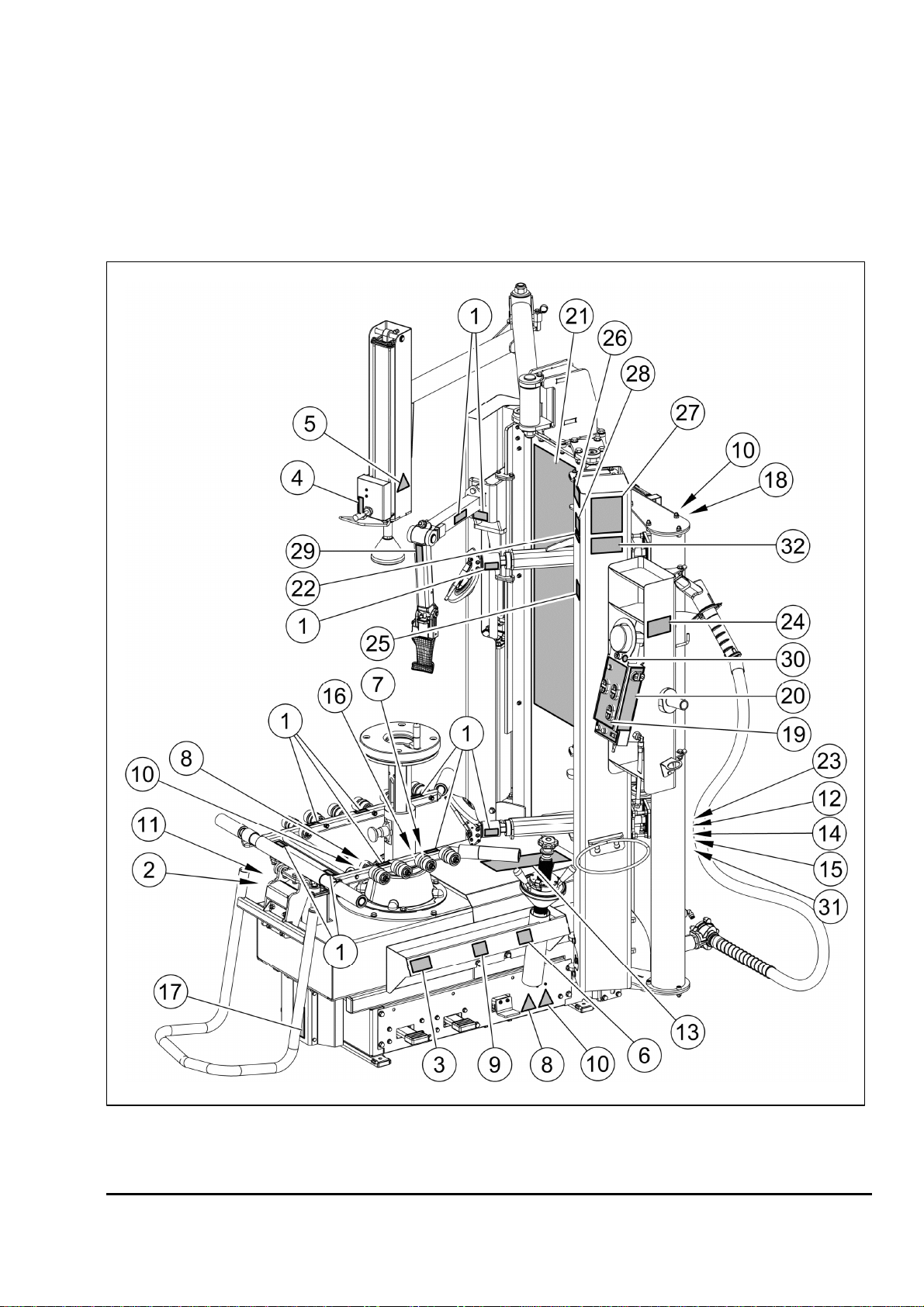
Decal Placement....................................................................................................3
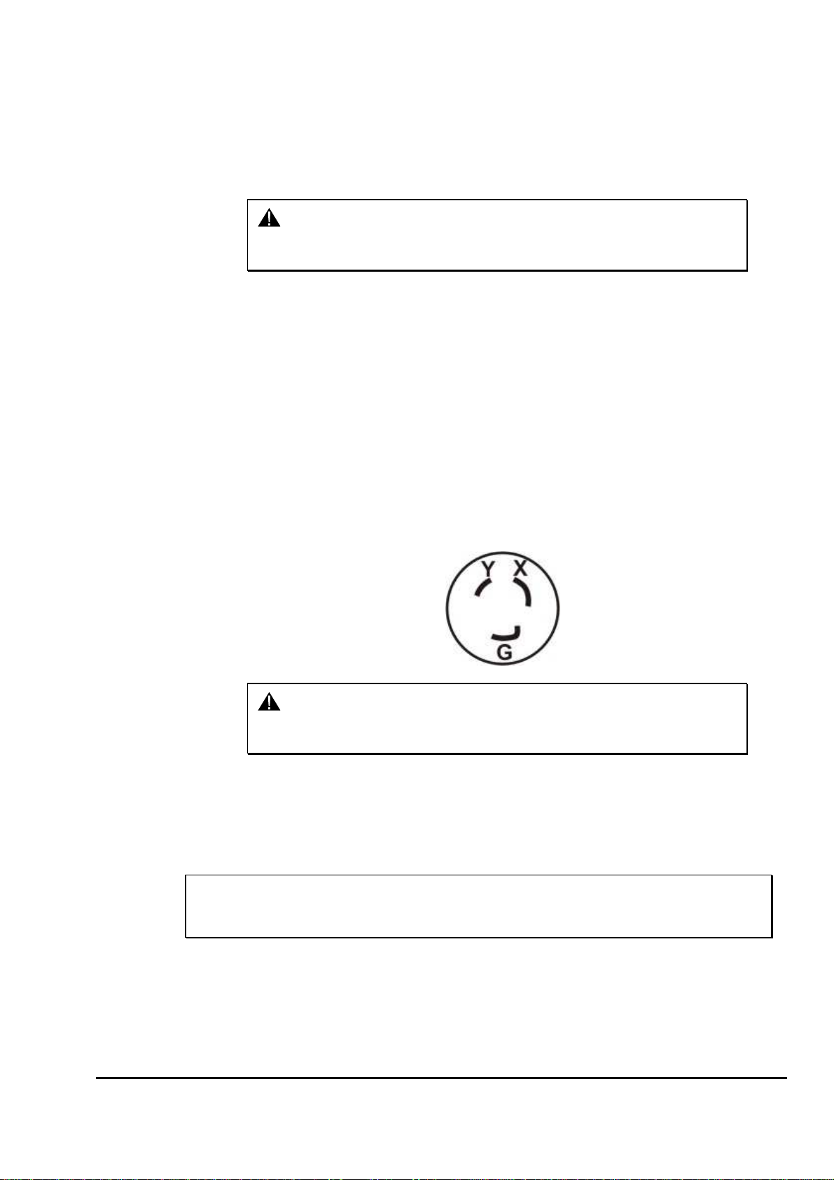
Electrical.................................................................................................................5
Specific Precautions/Power Source.......................................................................5
Turning Power ON/OFF.........................................................................................5
Re-starting..............................................................................................................5
Equipment Installation and Service........................................................................6
Equipment Specifications.......................................................................................6
Safety Summary.....................................................................................................6
1.3 Wheel Lift Pedal .....................................................................................................7
1.4 Wheel Rotation Pedal.............................................................................................7
1.5 Air Inflation Pedal....................................................................................................7
1.6 Inflator and Pressure Limiter ..................................................................................8
1.7 Bead Press Arm .....................................................................................................8
1.8 Push Button Controls..............................................................................................8
1.9 Equipment Components.........................................................................................9
1.10 Tool Head...........................................................................................................10
Tool Head Damage Prevention............................................................................10
2. BASIC PROCEDURES.................................................................................12
2.1 Placing Wheel on TC............................................................................................12
Wheel Support Plate Height Adjustment..............................................................12
Standard and High Offset Wheels.......................................................................13
Reverse Drop Center Wheels..............................................................................14
Large Pilot Hole Wheels ......................................................................................16
2.2 Bead Loosening....................................................................................................17
2.3 Demounting Tires from Rim .................................................................................18
2.4 Mounting Tire to Rim ............................................................................................20
2.5 Mounting Tough, Low Profile Tires.......................................................................24
2.6 Matching/Optimizing of Tire to Rim ......................................................................25
2.7 Head position memorization.................................................................................26
Head position memorization.................................................................................26
Recall the head position.......................................................................................26
Delete the memorized position.............................................................................26
Reset position ......................................................................................................27
2.8 Tire Inflation..........................................................................................................27
2.9 Removal of Wheel................................................................................................28
3. MAINTENANCE AND CALIBRATION ..........................................................29
3.1 Maintenance Schedule.........................................................................................29
3.2 Accessories Contained in the Packaging.............................................................30

TCA34R Series Changer Operation Instructions Getting Started •
••
•1
1. GETTING STARTED
1.1 Introduction
This manual provides operation instructions and information required to maintain the
TCA34R series tire changer.
The owner of the Tire Changer is solely responsible for arranging technical training.
The Tire Changer is to be operated only by qualified trained technicians. Maintaining
records of personnel trained is solely the responsibility of the owner and
management.
This manual assumes the technician has already been trained in basic tire changing
procedures.
“References”
This manual assumes that you are already familiar with the basics of tire changing.
The first section provides the basic information to operate the Tire Changer. The
following sections contain detailed information about equipment, procedures, and
maintenance. “Italics” are used to refer to specific parts of this manual that provide
additional information or explanation. For example, refer to “Equipment Components,”
page 9. These references should be read for additional information to the instructions
being presented.
The owner of the Tire Changer is solely responsible for arranging technical training.
The Tire Changer is to be operated only by a qualified trained technician. Maintaining
records of personnel trained is solely the responsibility of the owner or management.
1.2 For Your Safety
Hazard Definitions
Watch for these symbols:
CAUTION: Hazards or unsafe practices, which could result in minor
personal injury, or product or property damage.
WARNING: Hazards or unsafe practices, which could result in
severe personal injury or death.
DANGER: Immediate hazards, which will result in severe personal
injury or death.
These symbols identify situations that could be detrimental to your safety and/or
cause equipment damage.

2 •
••
•Getting Started TCA34R Series Changer Operation Instructions
IMPORTANT SAFETY INSTRUCTIONS
Read and follow all caution and warning labels affixed to equipment and tools.
Read and understand all instructions before operating this machine.
Misuse of this equipment can cause personal injury and shorten the life of the Tire
Changer.
To prevent accidents or damage to the Tire Changer, use only Hunter recommended
procedures and accessories.
Wear OSHA approved eye protection while operating the Tire Changer.
Wear non-slip safety footwear when operating the Tire Changer.
Do not wear jewelry or loose clothing when operating theTire Changer.
Wear proper back support when lifting or removing wheel from the Tire Changer.
Never stand on theTire Changer.
WARNING: Keep hands and clothing clear of moving parts. Keep
hands clear of upper roller when bead loosening or
rotating clamped wheel. Do not lean or reach over tire
when inflating.
WARNING: Do not exceed these pressure limitations:
SUPPLY LINE PRESSURE (from compressor) 175 PSI.
OPERATING PRESSURE (gauge on regulator) 115 PSI.
BEAD SEATING PRESSURE (gauge on hose) 40 PSI.
WARNING: Never mount a tire to a rim that is not the same diameter
(e.g., 16 1/2 inch tire mounting on a 16 inch rim).
WARNING: After loss of air line pressure ALWAYS raise the wheel
lift pedal to prevent the wheel lift from rising quickly
during first operation.
DANGER: Activate blast inflation nozzle only when seating bead.
CAUTION: Do not hose down or power wash electric tire changers.
Bleed air pressure from system before disconnecting supply line or other pneumatic
components. Air is stored in a reservoir for operation of the blast inflation nozzle. Air
pressure can be bled from the system by pulling up on the knob located on top of the
regulator, and then turning it counterclockwise.
Do not activate the blast inflation nozzle if the tire is not properly clamped.
Do not operate Tire Changer with worn rubber or plastic parts.
Wheels equipped with low tire pressure sensors or special tire and rim design may
require certain procedures. Consult manufacturer’s service manuals.
SAVE THESE INSTRUCTIONS

TCA34R Series Changer Operation Instructions Getting Started •
••
•3
Service and maintain machine regularly as outlined in “Maintenance and Calibration,”
on page 29. For further information contact:
Hunter Engineering Company
11250 Hunter Drive
Bridgeton, Missouri 63044
(314) 731-3020
http://www.hunter.com
Decal Placement

4 •
••
•Getting Started TCA34R Series Changer Operation Instructions
1 RP6-1541 DECAL-DANGER
2 128-279-2 DECAL-HUNTER
3 RP6-999916340 LIFTING DEVICE PEDAL PLATE
4 RP6-999914700 BEAD DEPRESSING CONTROLS PLATE
5 RP6-2166 BEAD BREAKER HAND DANGER INDICAT. PLATE
6 RP6-3691 DECAL-INFLATION
7 RP6-4221 GROUNDING PLATE
8 RP6-4244 DECAL-ROTATING PARTS DANGER INDICATING
9 RP6-710211210 DECAL-ROTATION DIRECTION
10 RP6-99990758 DECAL-ELECTRICITY DANGER
11 RP6-999915200 SERIAL NUMBER PLATE
12 RP6-1594 DECAL-INSTALLATION DATE
13 128-1241-2 DECAL-KEEP CLEAR
14 RP6-999916311 DECAL-RUBBISH SKIP
15 128-1345-2 DECAL-NEMA L6-20P
16 RP6-4182 DECAL-MOTOR SPECIFICATIONS
17 RP6-999916880 MAX. CAPACITY 80 KG (176 LBS) PLATE
18 RP6-999912430 230V 50HZ 1PH PLATE
19 RP6-999920960 CONTROL PANEL PLATE
20 128-1853-2 DECAL-TCA34R CONTROL PANEL
21 128-1854-2 DECAL-TCA34R NAMEPLATE
22 128-435-2 DECAL-REMOVE CLIP-ON WEIGHTS
23 128-285-2 DECAL-WARNING PRESSURE LIMITATIONS
24 128-1149-2 DECAL-WARNING AIR BLAST
25 128-323-2 DECAL-EYE PROTECTION
26 128-287-2 DECAL-WARNING INFLATION
27 128-284-2 DECAL-SAFETY INSTRUCTIONS
28 128-1213-2 DECAL-TCA TPMS SENSOR
29 128-1194-2 DECAL-ATTENTION TCA ARM
30 128-501-2 DECAL-MAN. TIRE BLEED VALVE
31 RP6-999923160 DECAL-WARNING PROP 65
32 128-286-2 DECAL-DANGER AIR BLAST

TCA34R Series Changer Operation Instructions Getting Started •
••
•5
Electrical
The Tire Changer is manufactured to operate at a specific voltage and amperage
rating.
Make sure that the appropriate electrical supply circuit is of the same voltage and
amperage ratings as marked on the Tire Changer.
WARNING: DO NOT ALTER THE ELECTRICAL PLUG. Plugging the
electrical plug into an unsuitable supply circuit will
damage the equipment.
Make sure that the electrical supply circuit and the appropriate receptacle is installed
with proper grounding.
To prevent the possibility of electrical shock injury or damage to the equipment when
servicing the Tire Changer, power must be disconnected by removing the power cord
from the electrical power outlet.
After servicing, be sure the Tire Changer ON/OFF switch is in the “O” (off) position
before plugging the power cord into the electrical power outlet.
Specific Precautions/Power Source
The Tire Changer is intended to operate from a power source that will apply 208-
230VAC, 1 phase, 15 amp 50/60 Hz, power cable includes NEMA 20 amp plug, L6-
20P, between the supply conductors of the power cord. The power cord supplied
utilizes a twist lock connector, NEMA L6-20P. This machine must be connected to a
20 amp branch circuit. Please refer all power source issues to a certified electrician.
Refer to “Installation Instructions for Tire Changer.
CAUTION: A protective ground connection, through the grounding
conductor in the power cord, is essential for safe operation.
Use only a power cord that is in good condition.
Turning Power ON/OFF
The ON/OFF switch is located on the back of the Tire Changer. To turn the Tire
Changer “ON,” press the “I” side of the ON/OFF switch. To turn the Tire Changer
“OFF,” press the “O” side of the ON/OFF switch.
IMPORTANT: After turning on the Tire Changer the user must wait 30 seconds for the
motor controller to “learn” the position of the rotation pedal before operating
the tire changer.
Re-starting
If a rotation issue is encountered, re-start the tire changer using the following
procedure:
1. Switch the tire changer power switch to the “off” position.

6 •
••
•Getting Started TCA34R Series Changer Operation Instructions
2. Wait 1 minute to discharge the drive system.
OR
Lift the rotation pedal (reverse) to discharge the drive system.
3. Do NOT touch the rotation pedal for 30 seconds. This will allow the pedal to
“learn” its new position.
4. Operate the tire changer normally.
Equipment Installation and Service
A factory-authorized representative should perform installation.
This equipment contains no user serviceable parts. All repairs must be referred to a
qualified Hunter Service Representative.
Equipment Specifications
Electrical
Voltage: 208-230VAC, 1 phase, 50/60 Hz, power cable includes
NEMA 20 amp plug, L6-20P
Amperage: 15 amperes
Wattage: 4200 watts (peak)
Air
Air Pressure Requirements: 115-175 PSI (8÷12 bar)
Approximate Air Consumption: 4 CFM (110 Liters/Minute)
Mechanical
Clamping System Rotating
Speed: CW – variable up to 15 rpm
CCW – 7rpm
Torque: 867 ft-lbs
Max. Tire Diameter: 54” in.
Max Bead Roller Opening Width:
15 in.
Diameter Range: 10÷34 in.
Bead Roller Power; Each Roller: 2645 lbs.
Safety Summary
Explanation of Symbols
These symbols may appear on the equipment.
Alternating current.
Earth ground terminal.

TCA34R Series Changer Operation Instructions Getting Started •
••
•7
Protective conductor terminal.
l ON (supply) condition.
OFF (supply) condition.
Risk of electrical shock.
Stand-by switch.
1.3 Wheel Lift Pedal
Press down on the wheel lift pedal to raise wheel lift. When the pedal is released the
wheel lift will lower.
CAUTION: The wheel lift may rise quickly during the first operation after
loss of air line pressure. This can be mitigated by first lifting
on wheel lift pedal before pressing down to operate wheel lift.
1.4 Wheel Rotation Pedal
The middle pedal on the Tire Changer base controls the rotation of the wheel. Refer
to “Equipment Components,” on page 9.
Step down on the pedal to rotate the wheel clockwise (variable speed).
Lift the pedal to rotate the wheel counterclockwise (fixed speed).
CAUTION: Keep hands clear of wheel, tire, and rollers during bead
loosening.
1.5 Air Inflation Pedal
The right-hand pedal on the Tire Changer base is a two-stage design. Refer to
“Equipment Components,” on page 9. The pedal controls the air going to the inflation
hose and the blast inflation nozzle.
CAUTION: Keep hands clear of wheel during sealing and seating of
bead.
CAUTION: When operating air inflation hose, do not lean over the tire.
Step down partially on the pedal to inflate tires through inflation hose.
Step down completely on the pedal to activate the blast inflator nozzle to seal tire
beads.
Refer to “2.8” on page 27 for complete inflation operation instructions.

8 •
••
•Getting Started TCA34R Series Changer Operation Instructions
1.6 Inflator and Pressure Limiter
As a safety device, the pressure limiter prevents the operator from using excessive
air pressure to seat the tire bead during tire inflation. Bead seating pressure should
never exceed 60 psi. If tires being mounted require more than 60 psi for inflation
pressure, the tire/wheel assembly should be removed from the tire changer, placed in
an inflation cage, and inflated per manufacturer’s instructions.
While inflating the tire, the pressure gauge will read zero until the inflation pedal is
released. At that time, the gauge will give the correct air pressure reading in the tire.
Refer to “2.8” on page 27 for complete inflation operation instructions.
1.7 Bead Press Arm
The bead press arm assists with tire mounting. The bead press arm moves in tandem
with the mount / demount head.
The controls on the bead press arm move the bead press up or down.
Refer to “Equipment Components,” on page 9.
1.8 Push Button Controls
The command unit governs all the movements necessary for complete bead roller
and tire tool operation. Refer to “Equipment Components,” on page 9.
The command unit is used to position both of the bead rollers and the tool head/ bead
press arm assembly independently. The manual controls are used in special
applications, such as PAX tires and wheels.

TCA34R Series Changer Operation Instructions Getting Started •
••
•9
1.9 Equipment Components

10 •
••
•Getting Started TCA34R Series Changer Operation Instructions
1.10 Tool Head
Tool Head Damage Prevention
NOTE: Always generously GREASE all
sides, including the bottom, of new
tool heads with tire lube paste
before first use.
If the tool head breaks near the middle the user was rotating the wheel and tire
assembly while pressing the “Tool Head Raise” button.
Use the following tips to prevent this type of tool head damage:
•DO NOT ROTATE while pressing the “Tool Head Raise” button.
•Ensure tool head cradles the rim edge before rotating during demount of
upper bead.
TOOL HEAD NOT CRADLED ON RIM TOOL HEAD CORRECTLY POSITIONED
Demounting

TCA34R Series Changer Operation Instructions Getting Started •
••
•11
If the tool head breaks at the mount/demount end the tire bead was not in the drop
center when mounting the upper bead.
Use the following tips to prevent this type of tool head damage:
•The bead MUST be in the drop center when mounting the upper bead.
•Use the bead press device and the upper roller to guide the bead into the
drop center.
•Ensure the bead is completely in the drop center on wheels where the
drop center is far from the bead seat.
BEAD NOT IN DROP CENTER BEAD FULLY IN DROP CENTER
Mounting
Bead not drop center.

12 •
••
•Basic Procedures TCA34R Series Changer Operation Instructions
2. BASIC PROCEDURES
2.1 Placing Wheel on TC
Wheel Support Plate Height Adjustment
The wheel support plate on the TC is height adjustable to allow a wide range of
wheels to be serviced.
Use the highest setting for most high offset wheels.
Standard wheels typically use the middle height.
Use the lowest height for most reverse drop-center wheels.
To adjust center support height, pull the knob outwards on center support and raise or
lower center support table to desired height.
LOCK/UNLOCK
KNOB

TCA34R Series Changer Operation Instructions Basic Procedures •
••
•13
Standard and High Offset Wheels
Adjust column and center support position to appropriate settings for the tire and
wheel combination to be serviced. This is typically the middle or highest setting.
Place the wheel, face up, on the center support. Ensure the anti-rotation pin enters a
lug hole in the wheel.
Insert wheel clamp, press down and twist clockwise 1/4 turn to lock into center
support.

14 •
••
•Basic Procedures TCA34R Series Changer Operation Instructions
The clamping shaft is equipped with a quick clamp cone to speed clamping. Simply
activate the Quick Clamp, drop the cone into place then hand tighten.
Reverse Drop Center Wheels
Adjust column and center support position to appropriate settings for the tire and
wheel combination to be serviced. This is typically the lowest setting.
Place anti-rotation pin protector and wheel protector pad on center support

TCA34R Series Changer Operation Instructions Basic Procedures •
••
•15
Place wheel, face-down, on center support ensuring anti-rotation pin inserts one lug
hole.
Insert wheel clamp, press down and twist clockwise 1/4 turn to lock into center
support.
The clamping shaft is equipped with a quick clamp cone to speed clamping. Simply
activate the Quick Clamp, drop the cone into place then hand tighten.

16 •
••
•Basic Procedures TCA34R Series Changer Operation Instructions
Large Pilot Hole Wheels
Adjust column and center support position to appropriate settings for the tire and
wheel combination to be serviced.
Place wheel on center support ensuring anti-rotation pin inserts one lug hole.
Place adapter cone on the wheel.
Insert wheel clamp, press down and twist clockwise 1/4 turn to lock into center
support.
Table of contents
Other Hunter Tyre Changer manuals

Hunter
Hunter TCX3000 User manual

Hunter
Hunter TC39 Series User manual

Hunter
Hunter TCX50H Series User manual

Hunter
Hunter Maverick Series User manual

Hunter
Hunter TCX56 User manual

Hunter
Hunter TCA28 User manual

Hunter
Hunter TC37 Series User manual

Hunter
Hunter TCX575 User manual

Hunter
Hunter TCX50 User manual

Hunter
Hunter TC33 Series User manual
Popular Tyre Changer manuals by other brands

Mondolfo Ferro
Mondolfo Ferro Super RM Series Operator's manual

Aston Global
Aston Global ATC-T5 Installation, operation and maintenance

Coats
Coats Rim Clamp APX80E operating instructions

foc.us
foc.us F640 user guide

Anova
Anova 99-556 Instruction and user's manual

Cormach
Cormach SUPER VIGOR 2450 Use and maintenance manual