B+K precision 865 User manual

User's Manual for
865
Universal 48-pindrive Programmer,
expandable up to 256.
866
Universal 48-pindrive Programmer with USB/LPT interface and ISP
capability
864
Universal 48-pindrive Programmer
844USB
Universal 40-pindrive Programmer with USB interface and ISP
capability
844A
Universal 40-pindrive Programmer with ISP capability
848
Universal Memory Programmer
848A
Universal Memory Programmer
849
MCS51 Series and Atmel AVR Microcontrollers Programmer with ISP
capability

COPYRIGHT ©1997 - 2005
B+K Precision Corporation
This document is copyrighted by B+K Precision, Yorba Linda -
California. All rights reserved. This document or any part of it may not
be copied, reproduced or translated in any form or in any way without
the prior written permission of B+K Precision
The control program is copyright B+K Precision, Yorba Linda -
California. The control program or any part of it may not be analyzed,
disassembled or modified in any form, on any medium, for any purpose.
Information provided in this manual is intended to be accurate at the
moment of release, but we continuously improve all our products.
Please consult manual on www.bkprecision.com .
B+K Precision assumes no responsibility for misuse of this manual.
B+K Precision reserves the right to make changes or improvements to
the product described in this manual at any time without notice. This
manual contains names of companies, software products, etc., which
may be trademarks of their respective owners. B+K Precision respects
those trademarks.
2

How to use this manual
This manual explains how to install the control program and
how to use your programmer. It is assumed that the user has
some experience with PCs and installation of software. Once
you have installed the control program we recommend you
consult the context sensitive HELP within the control program
rather than the printed User's Manual. Revisions are
implemented in the context sensitive help before the printed
Users Manual.
Note: Because this User's manual is common for more than
one B+K Precision programmers, read section(s) respective
programmer you have bought, please.
This manual contains two main sections:
Quick Start
Read this section if you are an experienced user. You will find
only specific information regarding installation of the control
program and use of your programmer. For more detailed
instructions you may read the Description in detail section or
the Troubleshooting chapter for the respective programmer.
Detailed description
Read this section for the respective programmer if you are a
less experienced user or if you need detailed information. You
may find some less relevant features of programmer described
here, but all programmer features are described in this section
along with details regarding installation of the control program.
Read this section to explore all of the features provided by your
programmer.
_____________________________________
Please, download actual version of manual from
B+K Precision WEB site (www.bkprecision.com), if current one
will be out of date.
3

Table of contents
How to use this manual.................................................................. 3
Introduction....................................................................................... 7
Products configuration ................................................................. 10
PC requirements.......................................................................... 10
Quick Start ...................................................................................... 12
Detailed description ....................................................................... 14
865.................................................................................................... 15
Introduction .................................................................................. 16
865 elements ............................................................................... 19
Connecting 865 to the PC............................................................ 20
Manipulation with the programmed device ..................................21
In-system serial programming by 865.......................................... 21
Self test and Calibration............................................................... 23
Technical specification................................................................. 23
866.................................................................................................... 29
Introduction .................................................................................. 30
866 elements ............................................................................... 32
Connecting 866 to the PC............................................................ 33
Manipulation with the programmed device ..................................34
In-system serial programming by 866.......................................... 34
Multiprogramming by 866 ............................................................ 36
Selftest and calibration................................................................. 36
Technical specification................................................................. 37
864.................................................................................................... 42
Introduction .................................................................................. 43
864 elements ............................................................................... 45
Connecting 864 to the PC............................................................ 46
Manipulation with the programmed device ..................................47
Self test and Calibration............................................................... 47
Technical specification................................................................. 48
844USB............................................................................................ 52
Introduction .................................................................................. 53
844USB elements........................................................................ 55
Connecting 844USB to PC .......................................................... 56
Manipulation with the programmed device ..................................56
In-system serial programming by 844USB .................................. 56
Selftest and calibration................................................................. 58
Technical specification................................................................. 58
844A................................................................................................. 63
Introduction .................................................................................. 64
844A elements............................................................................. 66
Connecting 844A to PC ............................................................... 67
Manipulation with the programmed device ..................................67
In-system serial programming by 844A ....................................... 68
Self test and calibration................................................................ 69
Technical specification................................................................. 70
848.................................................................................................... 74
Introduction .................................................................................. 75
848 elements ............................................................................... 76
4

Connecting 848 programmer to PC..............................................77
Manipulation with the programmed device...................................77
Self test and calibration................................................................78
Technical specification .................................................................78
848A .................................................................................................82
Introduction...................................................................................83
848A elements..............................................................................84
Connecting 848A programmer to PC ...........................................84
Manipulation with the programmed device...................................85
Technical specification .................................................................86
849....................................................................................................89
Introduction...................................................................................90
849 elements................................................................................92
849 elements................................................................................92
Connecting 849 programmer to PC..............................................92
Manipulation with the programmed device...................................93
In-System serial programming by 849..........................................93
Selftest and calibration.................................................................95
Technical specification .................................................................95
Software...........................................................................................99
The programmer software..........................................................100
File..............................................................................................102
Buffer..........................................................................................107
Device.........................................................................................113
Programmer................................................................................137
Options.......................................................................................142
Help............................................................................................146
Common notes..............................................................................149
Software .....................................................................................150
Hardware....................................................................................151
ISP (In-System Programming)....................................................152
Other...........................................................................................161
Troubleshooting and warranty ....................................................164
Throubleshooting........................................................................165
If you have an unsupported target device ..................................166
Warranty terms...........................................................................167
Appendix........................................................................................169
Appendix A - Device Problem Report form.................................170
Appendix C - AlgOR service.......................................................171
5

Conventions used in the manual
References to the control program functions are in bold, e.g.
Load, File, Device, etc. References to control keys are written
in brackets <>, e.g. <F1>.
Terminology used in the manual:
Device any kind of programmable integrated circuits or
programmable devices
ZIF socket Zero Insertion Force socket used for insertion of
target device
Buffer part of memory or disk, used for temporary data
storage
Printer port type of port of PC (parallel), which is
primarily dedicated for printer connection.
HEX data format - format of data file, which may be read with
standard text viewers; e.g. byte 5AH is stored as
characters '5' and 'A', which mean bytes 35H and
41H. One line of this HEX file (one record)
contains start address, data bytes and all records
are secured with checksum.
6

Introduction
7

This user's manual covers some B+K Precision programmers:
865, 866, 864, 844USB, 844A, 848, 848A and 849.
865 is a universal programmer and logic IC tester with 48
powerful pindrivers in base configuration, expandable up to
256. This design allows to easily adding new devices to the
device list. 865 provides very competitive price but excellent
hardware design for reliable programming. Best "value for
money" in this class.
866 is a fast universal USB/LPT interfaced universal
programmer and logic IC tester with 48 powerful pindrivers.
Using build-in in-circuit serial programming (ISP) connector the
programmer is able to program ISP capable chips in-circuit.
This design allows easily add new devices to the device list.
866 is a true universal and a true low cost programmer,
providing one of the best "value for money" in today's market.
864 is a universal programmer and logic IC tester with 48
powerful pindrivers. This design allows to easily adding new
devices to the device list. 864 is a true universal and a true low
cost programmer, providing one of the best "value for money"
in today's market.
844USB is a small, fast and powerful USB interfaced
programmer of all kinds of programmable devices. Using build-
in in-circuit serial programming (ISP) connector the
programmer is able to program ISP capable chips in-circuit. It
has design, which allows easily add new devices to the device
list. Nice "value for money" in this class.
844A is a small, fast and powerful programmer of all kinds of
programmable devices. Using build-in in-circuit serial
programming (ISP) connector the programmer is able to
program ISP capable chips in-circuit. It has design, which
allows to easily adding new devices to the device list. Nice
"value for money" in this class.
848 is a small and powerful EPROM, EEPROM, Flash EPROM
and serial EEPROM programmer and static RAM tester,
designed for professional mobile applications. In addition, 848
programmer with auxiliary modules support also
microprocessors (MCS48, MCS51, PIC, AVR), GALs, etc.
Programmer can work with 'true LV' device too - from 2V.
848A is a little and powerful programmer for EPROM,
EEPROM, Flash EPROM, NVRAM, serial EEPROM and static
RAM tester.
849 is little, powerful and very fast portable programmer for
MCS51 series and Atmel AVR Microcontrollers with ISP
8

capability. 849 enables also programming serial EEPROM with
interface types IIC (24Cxx), Microwire (93Cxx) and SPI
(25Cxx).
All our programmers work with almost any IBM PC Pentium
compatible or higher, portable or desktop personal computers.
No special interface card is required to connect to the PC,
since programmers use the parallel (printer) port or USB port.
All programmers function flawlessly on systems running
Windows 95/98/Me/NT/2000/XP.
All programmers are driven by an easy-to-use, control
program with pull-down menus, hot keys and online help.
Control program is common for all these B+K PRECISION
programmers (865, 866, 864, 844USB, 844A, 848, 848A and
849).
Advanced design, including protection circuits, original brand
components and careful manufacturing allows us to provide a
one-year warranty on parts and labor for these programmers
(limited 25,000 cycle warranty on ZIF socket).
Free additional services:
•free technical support (phone/fax/e-mail).
•free lifetime software update via Web site.
Free software updates are available from our
Internet address www.bkprecision.com
We also offer the following new services in our customer
support program: Keep-Current and AlgOR.
•Keep-Current is a service by which B+K PRECISION ships
to you the latest version of the control program for
programmer and the updated user documentation. A Keep-
Current service is your hassle-free guarantee that you always
have access to the latest software and documentation, at
minimal cost.
•AlgOR (Algorithm On Request) service allows you to receive
from B+K PRECISION software support for programming
devices not yet available in the current device list.
Note: We don’t recommend use programmers 864, 848 and
848A for In-circuit programming.
9

Products configuration
Before installing and using your programmer, please carefully
check that your package includes all next mentioned parts.
865
866
864
844USB
844A
848A
848
849
programmer ••••••••
LPT cable •••- ••••
USB cable - •- •- - - -
power supply ••••••••
diagnostic POD •••••- ••
ISP cable - •- ••- - •
ZIF anti-dust cover •••••- ••
User’s manual •••- •- - -
Quick Guide - - - •- •••
registration card ••••••••
shipping case ••••••••
If you find any discrepancy with respective parts list and/or if
any of these items are damaged, please contact your
distributor immediately.
PC requirements
Minimal PC requirements
•PC Pentium 166
•32MB RAM
•one CD drive
•HDD, 40 MB free space
•operating system Windows 95/98/Me/NT/2000/XP
•one parallel (LPT) port with nothing attached (for
programmers connected via LPT port)
•USB port ver. 1.1 or later (for programmers connected via
USB port)
Recommended PC requirements
•Pentium PC III 800 MHz or higher
10

•256 MB free RAM
•one CD drive
•HDD, 50 MB free space
•operating system: Windows XP
•LPT printer port supporting EPP/ECP modes (for
programmers connected via LPT port)
•USB port ver. 1.1 or later (for programmers connected via
USB port)
Note: For convenience, we suggest that you use a
supplementary multi I/O card to provide an additional printer
port (LPT2 for example), in order to avoid sharing the same
LPT port between printer and programmer.
11

Quick Start
12

Installing programmer hardware
•switch off the PC and programmer
•connect the communication port of programmer to a printer
port of PC using cable supplied
•switch on the PC
•connect the connector of the power supply adapter to the
programmer
Installing the programmer software
Run the installation program from the CD (Setup.exe) and
follow the on-screen instructions. Please, for latest information
about the programmer hardware and software see
www.bkprecision.com .
Using programmer software
Launch PG4UW.exe to enter the control program. The menu
Device contains the device manipulation commands. The
menu File contains commands for files and directories. The
menu Buffer is to be used for buffer manipulation.
Programming a device - the shortest way
Use the hot key <Alt+F5> to input the device name and/or
manufacturer to select the desired type of target device. If you
want to copy an existing device, insert it into the ZIF socket of
the programmer and then press key <F7>. If you want to
program a target device with data from a disk press key <F3>
and read the appropriate file into the buffer. Then insert your
target device into the ZIF socket. To check if the device is
blank - press key <F6>. Now you can program the device by
pressing key <F9>. After programming you may perform
additional verification by pressing key <F8>.
13

Detailed description
14

865
15

Introduction
865 is a new generation of Windows 95/98/Me/NT/2000/XP
based B+K PRECISION universal programmers built to meet
the rigorous demands of the leading engineers and
programming centers.
865 supports all kinds of types and silicon technologies of
programmable devices. It provides very competitive price but
excellent hardware design for reliable programming. Best
"value for money" in this class.
865 interfaces with the IBM PC Pentium compatible or higher,
portable or desktop personal computers. Programmer allows
you to directly connect to your PC through any standard
parallel (printer) port (no special interface card needed). We
recommend use parallel (printer) port on PCI bus, IEEE
1284 compatible (ECP/EPP). The 865 control program
support standard IEEE1284 also.
865 offer very fast programming due high-speed FPGA driven
hardware and support of ECP/EPP parallel port. Consequently
and due special protocol is communication between PC and
865 programmer fast and very reliable. The programming
AT29C040A takes about 28 seconds it is faster than most its
competitors. As a result, this programmer is optional solution
for middle quantities programming in production or
programming centers.
Scheme of 865 programming system
865, base configuration
•865, base unit
•865, DIL48 socket module
For following text, term 865 means 865 in base configuration.
16

865 has 48 powerful pindrivers in base unit, expandable up to
256 pindrivers using "pindriver expansion" modules. Advanced
pin drivers incorporate high-quality high-speed circuitry to
deliver programming and testing performance without
overshoot or ground bounce for all device technologies. Pin
drivers operate down to 1.8V so you'll be ready to program the
full range of today's advanced low-voltage devices.
Modular design of 865 allows adapting the programmer
according to customers needs either as very flexible universal
programmer for laboratory or high efficient multi-programmer in
production line. Multiprogramming capability for most of
supported devices is accomplished by using "multiple socket"
modules.
Powerful pindriver provides logic level, pull-up/pull-down, clock,
ground, one VCC supply and two programming supply and,
certainly read, on each of all 48 pins independently. This
advanced design give it the ability to program almost every
programmable device in DIL up to 48 pins without adapter or
family specific module. Support for today and tomorrow
programmable devices gives engineers the freedom to choose
the optimum device for new design.
865 isn't only programmer, but also tester of TTL/CMOS logic
ICs and memories. Furthermore, it allows generate of user-
definable test pattern sequences.
The programmer has on-board intelligence, comprise of
powerful Microcontroller system and support devices. 865 has
been designed for multitasking operating systems and is
able to perform time-critical programming sequences
independently of the PC operating system status and without
being interrupted by any another parallel process running on
the PC. Consequently, 865 works without any problem on
systems running Windows 95/98/Me/NT/2000/XP.
The programmer performs device insertion test (wrong or
backward position) and contact check (poor contact pin-to-
socket) before it programs each device. These capabilities,
supported by over current protection and signature-byte check
help prevent chip damage due to operator error.
Built-in protection circuits eliminate damage of programmed
device due to mains supply fluctuations, communication error
or if PC is frozen. In event of such errors Microcontroller in
programmer performs, independently on the PC, exactly
specified sequence of steps, so that programmed target device
remains intact. Programmer's hardware offers enough
resources for self test, that control program is any time be
able to check pindrivers, present and correct level of all
17

voltages, check the timing and communication between
programmer and PC.
An optimally designed printed circuit minimizes negative
programming effects at the socket (such as ground bouncing,
supply voltage instability). All the inputs of the 865
programmer, including the ZIF socket, connection to PC and
power supply input, are protected against ESD to protect the
programmer and programmed circuits against damage due
ESD.
865 performs programming verification at the marginal level
of supply voltage, which, obviously, improves programming
yield, and guarantees long data retention.
Various socket converters are available to handle device in
PLCC, SOIC, PSOP, SSOP, TSOP, TSSOP, TQFP, QFN
(MLF), SDIP, BGA and other packages.
Devices with more than 48 pins are supported by
•pindriver expansion module and universal single socket
module
•simple special package converters
865 programmer is driven by an easy-to-use control program
with pull-down menu, hot keys and on-line help. Selecting of
device is performed by its class, by manufacturer or simply by
typing a fragment of vendor name and/or part number.
Standard device-related commands (read, blank check,
program, verify, erase) are boosted by some test functions
(insertion test, signature-byte check), and some special
functions (autoincrement, production mode - start immediately
after insertion of chip into socket).
All known data formats are supported. Automatic file format
detection and conversion during load of file.
The rich-featured autoincrement function enables to assign
individual serial numbers to each programmed device - or
simply increments a serial number, or the function enables to
read serial numbers or any programmed device identification
signatures from a file.
The software also provide a many informations about
programmed device. As a special, the drawing of all available
packages are provided. The software provide also explanation
of chip labeling (the meaning of prefixes and suffixes at the
chips) for each supported chip.
It is important to remember that in most cases new devices
require only a software upgrade since the 865 has 48 true
18
pin drivers, which can perform as required under program
control. With our prompt service new devices can be added to
the current list within hours!
Advanced design including protection circuits, original brand
components and careful manufacturing allows us to provide a
one-year warranty on parts and labor for the 865 (limited
25,000-cycle warranty on ZIF socket).
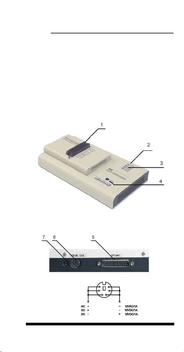
865 elements
DIL48 socket module with 48 pin ZIF socket
LED indicator power/sleep
LED indicators for work result
YES! Button
Connector for PC <-> 865 communication cable
Power supply connector
Internal use connector
Power supply connector
19

Note: Due to low power consumption of 865 in inactive mode,
it doesn't require power switch. When the power LED indicator
glows with a low intensity, the 865 is in inactive mode.
Connecting 865 to the PC
Switch off PC and programmer. Insert the communication
cable included with your 865 programmer package to a free
printer port on your PC. If your computer is equipped with only
one printer port, substitute the programmer cable for the printer
cable. Connect the opposite cable end to the programmer.
Screw on both connectors to counter-connectors. This is very
important. It may be uncomfortable to switch between printer
cable and programmer cable, though it is not recommended to
operate the 865 programmer through a mechanical printer
switch. Use of an electronic printer switch is impossible. But
you can install a second multi-I/O in your computer, thus
obtaining a supplementary printer port, says LPT2. So your
printer may remain on LPT1 while the programmer on LPT2.
Switch on the PC.
Connect the mains connector of the power supply (or the wall-
plug power supply itself) to a mains plug, and then connect the
mini-DIN connector to the programmer's connector labeled
"12VAC". At this time all 'work result' LEDs (and 'POWER'
LED) light up successive and then switch off. Once the
POWER LED lights with low brightness then the 865
programmer is ready to run.
Next run the control program for 865.
Caution! If you don't want to switch off your PC when
connecting the 865, proceed as follows:
•When connecting the programmer to the PC: FIRST insert
the communications cable and THEN the power-supply
connector.
•When disconnecting the programmer from the PC: FIRST
disconnect the power-supply connector and THEN the
communication cable.
From 865's point of view the connecting and disconnecting
sequence is irrelevant. Protection circuits on all programmer
inputs keep it safe. But think of your PC please.
Problems related to the 865
PC
interconnection, and their removing
If you have any problems with 865 PC interconnection,
see section Common notes please.
20
This manual suits for next models
7
Table of contents
Other B+K precision Motherboard manuals


