manuals.online logo
Brands
  1. Home
  2. •
  3. Brands
  4. •
  5. Renesas
  6. •
  7. Motherboard
  8. •
  9. Renesas RZ/A2M User manual

Renesas RZ/A2M User manual

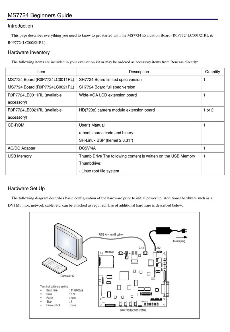
Quick Start Renesas Evaluation Board Kit
for RZ/A2M
Display Output
Board
User Switches
User LED
MIPI Camera
Header
Reset Switch
Debugger Header
Power LED
J-Link Lite
Debugger
Power Switch
CPU Board
Socket
CPU Board
Sub Board
MIPI 8MP
Camera Board
USB Power
(Mini USB)
USB Serial
(Micro USB)
NOTE: This Quick Start Guide covers installation of the e2studio IDE (available from https://www.renesas.com/e2studio
where version 7.3.0 or later is required). An active internet connection is requiredfor downloading the installer.
1. Installation
Do not connect the debugger module until the software support has been installed.
Internet access is required during the installation process.
1. Software for this Renesas Evaluation Board Kit is available for download from;
2. After download the installerwill run and displaythe Welcome dialog box. Follow theon-screen instructions to install
the IDE software, selectingthe RZ device family when prompted.This process will take several minutes.
Note:
Windows™10 / 8.1 / 8 / 7 users may see “User Account Control” dialog box. If applicable, enter the administrator
password and click ‘Yes’.
The Windows™driver signing dialog box may be displayed. Please accept the driver to continue.
Users may seea Renesastrust certificatedialog box. If applicable select the checkbox to trustthe certificate.
https://www.renesas.com/rza2mevb
2. Preparing the Evaluation Board Kit
3. Connect the CPUboardto the sub board usingthe 204-pin connector (note the keyslot isto the left of centre).
Orientate at approximately 45° fromhorizontal, inserting the edgeconnector fully into the socketbeforegently
rotatingthe CPUboarddown flat until the clampslock the board in place.
2
1
Sub Board
CN1
Actions for inserting CPU
Board in Sub Board CN1
4. Connect the Display Output Board to the display connector(CN15 LCD) onthe sub board. The centralkey ensures
correctorientation byaligning it with the slotin the socket.
5. Connect the Display Output Board to an external monitor capable of 800x600 resolution using a monitor cable (not
supplied).
6. Connect the camera module to the camera connector (CN2 MIPI) on the CPU board.
Open the connector bypulling up on the tagsat either side, then insert the camera’s ribbon cable. The correct
orientation is with the contacts on the ribbon cable facing the CPU, and the blue insulated rectangle to the outside.
To hold the cable firmly, push down on the top of the connectoruntilit clips inplace.
Pull tags to open
Push centre to close
7. Connect the J-Link LITE Segger debugger module to the debugger connector (CN5 Coresight 20) on the CPU
board usingthe ribbon cable.Ensure that pin 1 (red strand) mates with the triangle mark ► on the PCB silk screen.
8. Connect the debuggermodule to a USB port on the host PC. The green LED on the debuggerwillilluminate.
9. The debugger driverswillnow be installed. Note that,this may take up toa minute and administrator privileges will
be required.
Windows™ 7
Windows™ 8.1 / 8
Windows™ 10
“Device driver software installed
successfully” pop-up will appear in
the Windows™ Taskbar and
installation will complete.
An icon will appear in the Windows™
Taskbar and installation will
complete.
A Windows™ taskbar buttons of
“Device Setup” willappear in the
Windows™ Taskbar and installation
will complete.
10. Connect a USB cable between the micro USB Serial connector (CN5 UART) on the sub board and a USB porton
the hostPC. The board willenumerate inthe Device Manager underPorts (COM &LPT) Communications Port
(COMn) as “RZA USB Serial Port”. The micro USB Serial connector (CN5 UART) on the sub board may be used to
providea serialconsole forthe sample applications.
If you have not previously installed another Renesas kit with this virtual serial port driver, or if the boardenumerates
as an “Unknown device,”then disconnect the board and install the “RZ/A2M Evaluation Board Kit inf File for USB to
Serial Conversion IC” available from https://www.renesas.com/software/D6002724.html
a. Note: Windows™10 / 8.1 /8 / 7 usersmay see “User Account Control”dialog box. If applicable, enter
the administrator password and click ‘Yes’.
b. The Windows™driver signing dialog box may be displayed. Please accept the driver to continue.
11. Use any serial terminal (e.g.HyperTerminal, Tera Term orPuTTY), select the appropriate COMport and set the
baud-rate to 115200 bps,Databits to8, Stop bitsto 1,Parity to Noneand FlowasNone.
12. Connect a USB cable between the mini USB Power connector (CN13 USB-F) on the sub boardand a USB port on
the host PC.
13. Apply power by moving SW1 away from the power jack; the blue power LED will illuminate.
14. Power down the systemby moving SW1towards the power jack.
3. Preparing the e2studio development environment
Renesas e2 studio integrates various tools such as compiler, assembler, debugger and editor into a common graphical
user interface.
15. Start e2 studio:
Windows™ 7: Start Menu >All Programs > RenesasElectronics e2studio >e2 studio
Windows™ 8.1 & 8: From Apps View , RenesasElectronics e2studio > e2 studio
Windows™ 10: Start Menu > All Apps > Renesas Electronics e2studio > e2 studio
16. In the ‘Select aworkspace’folderthat appears,browse a suitable locationand foldername to save yournew
workspace to. Click ‘OK’ to continue.
17. In the ‘Toolchain Registry’dialog box select Renesas Toolchains and ensure that ‘GCC ARM Embedded
6.3.1.20170620’ is selected. Click ‘Register’. A dialog box will appear "Selected Toolchains were successfully
integrated with e2 studio". Click ‘OK’.
18. If the ‘Code GeneratorRegistration’dialog box is shown, click ‘OK’ and follow the on-screen instructions to restart
e2studio. Thisis requiredbefore the Code Generatorcan be used.
19. To learn more onhow touse e2 studio, openthe program’s help filesby using Help> Help Contents.
4. Next Step
20. In the e2 studio Welcome screen, click the ‘Workbench’ arrow icon, on the farright.
You are ready to download and program an application from the RZ/A2M Simple Applications Package
(R01AN4494EJ).
21. Select one of the available application notes, and follow the instructions in the readme files,ensuring the correct
switch and jumpersettingsare made before applying power. Recommendations:
● If you have a display supporting 800x600 input,accessthe camera_display_sample (R01AN4477EJ).
● If you want to quickly check the kit’s operation, access the blinky_osfree_sample (R01AN4321EJ).
5. GNU ARM Compiler
The version of the compilerprovided with this evaluation board kit is fully functional.
6. User Manuals
The user manuals for this product are available at: https://www.renesas.com/rza2mevb
This includes, but not limited to:
● RZ/A2 Group User’s Manual: Hardware (R01UH0746EJ)
● CPU Board User’s Manual (R20UT4397EJ)
● Sub Board User’sManual(R20UT4398EJ)
7. Support
Online technical support and information is availableat: https://www.renesas.com/rza2mevb
Technical Contact Details
America: techsupport.america@renesas.com
Europe: https://www.renesas.com/eu/en/support/contact.html
Global & Japan: https://www.renesas.com/support/contact.html
© 2018-2019 Renesas Electronics Europe Limited. All rights reserved.
© 2018-2019 Renesas Electronics Corporation. All rights reserved.
Website: https://www.renesas.com/
D016404_11_S01_V02
R20UT4399EJ0200, 28-JAN-2019

Other Renesas Motherboard manuals

Renesas US082-OB1203EVZ User manual

Renesas

Renesas US082-OB1203EVZ User manual

Renesas ZSPM4121 Operating and installation instructions

Renesas

Renesas ZSPM4121 Operating and installation instructions

Renesas EK-RA6M1 User manual

Renesas

Renesas EK-RA6M1 User manual

Renesas CCE4510 User manual

Renesas

Renesas CCE4510 User manual

Renesas R0K572167 User manual

Renesas

Renesas R0K572167 User manual

Renesas RTK7FPA2E1S00001BE User manual

Renesas

Renesas RTK7FPA2E1S00001BE User manual

Renesas ZMOD4410 User manual

Renesas

Renesas ZMOD4410 User manual

Renesas RTKA211835DE0010BU User manual

Renesas

Renesas RTKA211835DE0010BU User manual

Renesas EK-RA6E2 v1 User manual

Renesas

Renesas EK-RA6E2 v1 User manual

Renesas ISL85003EVAL2Z User manual

Renesas

Renesas ISL85003EVAL2Z User manual

Renesas M3A-HS71 User manual

Renesas

Renesas M3A-HS71 User manual

Renesas ISL68201-99140DEMO1Z User manual

Renesas

Renesas ISL68201-99140DEMO1Z User manual

Renesas RA2 Series Installation and operation manual

Renesas

Renesas RA2 Series Installation and operation manual

Renesas S3A1 User manual

Renesas

Renesas S3A1 User manual

Renesas US082-FS1015EVZ User manual

Renesas

Renesas US082-FS1015EVZ User manual

Renesas RL78 Series User manual

Renesas

Renesas RL78 Series User manual

Renesas RA9530-R User manual

Renesas

Renesas RA9530-R User manual

Renesas ISL29501-ST-EV1Z User manual

Renesas

Renesas ISL29501-ST-EV1Z User manual

Renesas RA6 Series User manual

Renesas

Renesas RA6 Series User manual

Renesas QB-V850ESHG3-TB User manual

Renesas

Renesas QB-V850ESHG3-TB User manual

Renesas 8T49N240 User manual

Renesas

Renesas 8T49N240 User manual

Renesas RTK00V2XRC7746SFS User manual

Renesas

Renesas RTK00V2XRC7746SFS User manual

Renesas PEB383 QFN User manual

Renesas

Renesas PEB383 QFN User manual

Renesas RX23T Series User manual

Renesas

Renesas RX23T Series User manual

Popular Motherboard manuals by other brands

ASROCK FM2A58M-VG3+ user manual

ASROCK

ASROCK FM2A58M-VG3+ user manual

AXIOMTEK PICO312 user manual

AXIOMTEK

AXIOMTEK PICO312 user manual

Gigabyte Z490 VISION D user manual

Gigabyte

Gigabyte Z490 VISION D user manual

Asus Z9NH-D12 user manual

Asus

Asus Z9NH-D12 user manual

Avalue Technology EAX-Q67 user manual

Avalue Technology

Avalue Technology EAX-Q67 user manual

MSI MS-6301 manual

MSI

MSI MS-6301 manual

Intel DG41AN Product guide

Intel

Intel DG41AN Product guide

Intel DQ43AP Product guide

Intel

Intel DQ43AP Product guide

ASROCK E35LM1 R2.0 Quick installation guide

ASROCK

ASROCK E35LM1 R2.0 Quick installation guide

Freetech 586F52 user manual

Freetech

Freetech 586F52 user manual

Commell LV-67I user manual

Commell

Commell LV-67I user manual

Feig Electronic OBID i-scan ID ISC.LR.I/O-A Montage, installation

Feig Electronic

Feig Electronic OBID i-scan ID ISC.LR.I/O-A Montage, installation

Asus H110M-D instruction manual

Asus

Asus H110M-D instruction manual

Texas Instruments CC2530EMK quick start guide

Texas Instruments

Texas Instruments CC2530EMK quick start guide

AOpen MK33M(A) Easy installation guide

AOpen

AOpen MK33M(A) Easy installation guide

Wintech MV018 user manual

Wintech

Wintech MV018 user manual

Gigabyte GA-EP35-DS3 user manual

Gigabyte

Gigabyte GA-EP35-DS3 user manual

JETWAY JBC390F841VGU Technical manual

JETWAY

JETWAY JBC390F841VGU Technical manual

manuals.online logo
manuals.online logoBrands
  • About & Mission
  • Contact us
  • Privacy Policy
  • Terms and Conditions

Copyright 2025 Manuals.Online. All Rights Reserved.