BPS PRESTIGE 2 User manual

HEAD OFFICE :
VIA BIBAN 56 ( Z.I. )
31030 CARBONERA
TREVISO - ITALIA
TEL. ++39 0422 445363
FAX ++39 0422 398646
PLEASE NOTE :
THE INSTRUCTIONS GIVEN HEREIN APPLY ONLY TO THE COUNTRY MARKED
ON THE PLATE STUCK ON THE APPLIANCE.

1
TECHNICAL FEATURES
MODEL NO. PRESTIGE 2 PRESTIGE 4
CERTIFICATION NO. CE 1312BP4187
NOMINAL THERMAL INPUT
kW
2
4
NOMINAL THERMAL OUTPUT
kW
1.8
3.6
THERMAL EFFICIENCY µ
%
90 90
METHANE
G20 (9.45 kW) 0.22 0.42 0.42
CONSUMPTION METHANE
G25 (8.12 kW)
0.22 0.45 0.5
at + 15°C PROPANE
G31 (12.8 kW)
0.24 0.5 0.31
BUTANE
G30 /13.8 kW) 0.15 0.31 0.29
TREATED AIR DELIVERY at +
20°C mc/h 0.14 0.29 105
65 105 145
THERMAL JUMP 85 145 84 / 55
TANGENTIAL FANS Number of revolutions/1’ 64 / 45 84 / 55
1 1
VOLTAGE RATING
220
–
240 V/AC 50
-
60 Hz
INSTALLED ELECTRIC POWER Watt 80 100
NOISE LEVEL AT 3 m.
IN STANDARD INSTALLATION dB (a) 36 38
WEIGHT
Kg.
19
26
COMBUSTION AIR REQUIRED
VOLUME
mc/h 4 8
SMOKES MASS OUTPUT gr./ sec. 1.46 2.92
FEEDING PRESSURE - mbar
COUNTRY CATEGORY
G 20 G 25 G 30 G 31
ITALY II 2H3+ 20 30 37
FRANCE II 2Er3+ 20 25 28 37
BELGIUM I 2ErB/I3+ 20 25 28 37
SPAIN II 2H3+ 20 28 37
HOLLAND II 2L3B/P 25 30 30
PORTUGAL II 2H3+ 20 30 37
GERMANY II 2ELL3B/P
20 20 50 50
GREECE I 3+ 28 37
AUSTRIA II 2H3B/P 20 50 50
SWITZERLAND II 2H3B/P 20 50 50

2
P R E S T I G E 2 GLOBAL VIEW
Pict.1

3
PRESTIGE 4 GLOBAL VIEW
Pict.2

4
HOW TO INSTALL PRESTIGE 2 and PRESTIGE 4
”L” SIZE
Minimum = 300 mm
Maximum = 800 mm
SUPPLIED PIPE L = 500 mm
OPTION PIPE L = 800 mm
“L” SIZE
Minimum = 50 mm
Maximum = 300 mm
- WALL INSTALLATION -
SMOKES EXHAUST & AIR SUCTION DIRECT
TO & FROM OUTSIDE
- WALL INSTALLATION -
SMOKES EXHAUST & COMBUSTION AIR
SUCTION THROUGH THE OUTLET WINDOW
Pict.3

5
HOW TO INSTALL PRESTIGE 2 and PRESTIGE 4
- WALL INSTALLATION -
90° HORIZONTAL SMOKES EXHAUST &
COMBUSTION AIR INSIDE THE WALL
- WALL INSTALLATION -
90° HORIZONTAL SMOKES EXHAUST &
COMBUSTION AIR CROSSING TWO WALLS
Pict.4
The heaters of the “PRESTIGE” series are independent forced air convectors, fitted with
atmospheric burner and fan, expressly designed for room heating.
These “C 13” type appliances are sealed with respect to the room where they’ve been
installed in, with concentric combustion air suction pipes and smokes exhaust pipes, wall
outlet (Pict.3-4).
They are: PRESTIGE 2 and PRESTIGE 4.
INSTRUCTIONS

6
•Please carefully read all the instructions given in this booklet, as these are very useful for
both safe installation and proper use & maintenance.
•Installation to be carried out always strictly complying with the current standards of the
country where the device is going to be used, as well as following the instructions given
by the maker, of course. Only professionally qualified operators and authorized assistance
centers will be entitled to carry out installation. Should any wrong installation cause harm
to people or damage things, in no case the manufacturer will be held responsible for it.
•Please carefully check package and its contents before starting operating. If any doubt,
don’t use generator but ask the supplier.
•
Always keep package parts away from children reach, as those may be harmful.
•
Keep suction grids clear.
•In case of breakdown or failure: turn generator off, do not try to repair it on your own, call
operator.
•In order to ensure appliance correct working, have yearly checking and cleaning carried
out by qualified technical people only, following directions supplied by maker.
•If you’re going to leave convector off for a long time, please ensure that in no way this
would be harmful to anyone in any w
ay.
•This convector is to be used for heating purposes only. Any different use is not allowed as
it might be dangerous.
•
Always keep this handbook near convector.
•In case convector was placed in houses where disabled people and/or children live, then
place it safely away from their reach. Please note that temperature, on top of appliance,
can reach 100°C!
•In case of gas break-off, the appliance getting blocked, it would be necessary to make a
new start again ( see Start & Use chapter).
•In case of “flame checking hole” glass break, do not start the appliance. Call assistance
service.
INSTRUCTIONS for QUALIFIED INSTALLING OPERATORS
INSTALLATION
Inside the package you will find all the tools required for a correct installation, and at the end
of this manual you’ll see (page ?) the pattern required to mark holes on the wall for fixing
points and smokes outlet .
1. Mark fixing points & smokes exhaust outlet holes, depending on the heater, stay
minimum 100 mm up the floor.
2. Make holes.
3. Once you know wall width , add respectively 2 cm to the Ø 60 pipe and 4,5 cm. to the Ø
35 pipe. Connect the pipes to the heater and fix the Ø 60 pipe by the special screws
supplied.
4. Fix the heater to the wall by the plugs supplied, after having tested by a level the correct
position of the heater compared to the floor.
5. Fix the wind-proof terminal top outside by its special screws. Its smokes exhaust slots
must compulsorily be horizontal compared to the floor, while its combustion air suction
slots must be in the perpendicular way, always compared to the floor.
Fig.2 - Make holes.

7
6. Now assemble the shell, fix the side screws.
7. Connect the heater to the gas supply, by adopting a detecting tap
8. Connect the heater to the power mains. Check the ground connection.
POWER CONNECTION
This convector has been duly manufactured in compliance with the CEE 73/23 rule.
Connection to be made by means of a H05 RR-F, 3 pole cable, section must be minimum 0,75
sq. mm. or wider. Connect through the terminal panel (Ref.19 on Pict.17), by strictly attaining
to the directions given.
= Compulsory ground connection (yellow
-
green wire)
N
= Neutral phase connection (light blue wire)
L1
= Active phase connection ( brown wire)
VERY IMPORTANT : Neutral-phase connection must necessarily be most accurate.
Wrong polarities may cause the whole machine stop, in case of phase/phase net with
high passive capacity values or serious insulating faults between line conductors and
earth. In order to ensure safe working, an insulating transformer must be used. In this
case, call assistance service.
We recommend to make connection preferably in the permanent way by means of a bi-polar
switch with contacts being at least 3 mm. far from each other. Please remember : the ground
conductor must never be cut off. In case the connection is made by means of a reverse plug,
then inform the user that the connection cannot work if the plug is turned upside down.
N.B. : ROTATE THE PLUG TO GET THE CORRECT CONNECTION,
THEREFORE THE CORRECT WORKING OF THE HEATER !
GAS CONNECTION
The heater is provided at the gas inlet point with an ISO 7/1 R1 ⅜” or G S ISO 228 ⅜” thread
male nipple, depending on the country where the heater is working. The link must be made by
metal connections, complying with the current installation standards. Pay attention not to
force the nipple when making the link. At the end of the work check that it is actually sealed.
GAS TECHNICAL FIGURES
METHANE
(G20)
METHANE
(G25 – FRANCE/BELGIUM)
MODEL : PRESTIGE
2 PRESTIGE
4
MODEL : PRESTIGE
2 PRESTIGE
4
Ø of injectors in
mm.
1.2r
1.7r
Ø of injectors in
mm.
1.2r 1.7r
No. of injectors
1 1
No. of injectors
1 1
Pressure to the
injectors
in mbar
10
10
Pressure to the
injectors
in mbar
15
15
METHANE (G25)
(GERMANY – HOLLAND)
BUTANE/PROPANE
(G30/31)
MODEL : PRESTIGE
2 PRESTIGE
4
MODEL :
PRESTIGE
2 PRESTIGE
4

8
Ø of injectors in
mm. 1.3 r 1.85 r
Ø of injectors in
mm. 0.8 r 0.7r
1.1r 1r
No. of injectors 1 1
No. of injectors 1 1 1 1
Pressure to the
injectors
in mbar
10
10
Pressure to the
injectors
in mbar
30/
37
50 30/
37
50
GAS LINE INSTALLATION DIAGRAM
The diagrams here below show both those parts being supplied along with the appliance and
those to be supplied by the installer.
G20/G25 Gas Line DIAGRAM
TO BE
ASSEMBLED BY
THE INSTALLER:
1. gas tap
2. gas filter
3. vibration-free joint
ALREADY
ASSEMBLED: 4. safety double electro-
valve in class B
G30/G31 Gas Line DIAGRAM
TO BE
ASSEMBLED BY
THE INSTALLER:
1. gas tap
2. gas filter
3. vibration-free joint
4. pressure adjuster
ALREADY
ASSEMBLED:
5. safety double electro-
valve in class B
Pict.5
APPLIANCES BELONGING TO THE 1
st
CATEGORY
(APPLIANCES BEING ADJUSTED FROM THE MANUFACTURING STAGE, IN THE
FACTORY - pls. refer to the label).
BURNER
BURNER

9
-
No intervention is required. However we recommend to do as follows :
1. METHANE APPLIANCES (G20) (G25)
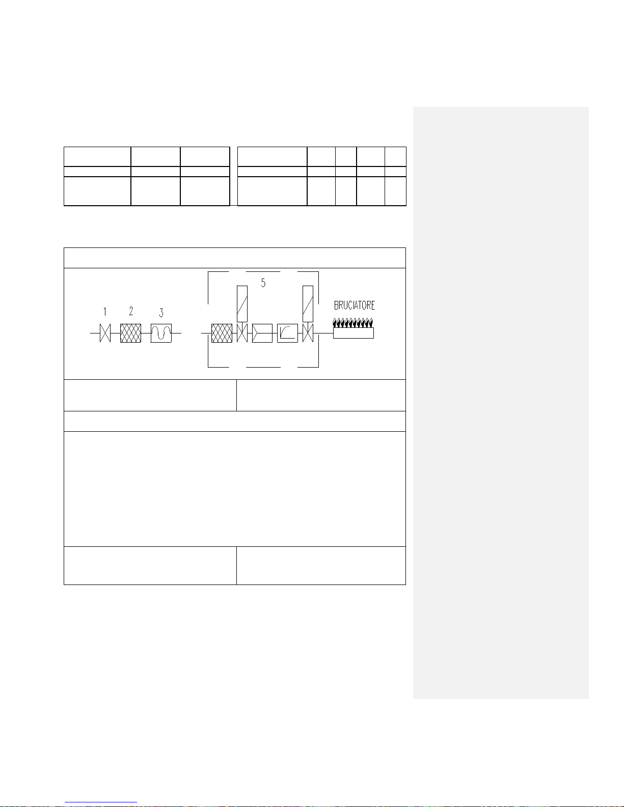
By a manometer on the “PV” point (Pict.6) compare the pressure value to the value stated on
the label. Should there be found a difference exceeding ±2 mbar, remove protection from
"RP" adjusting screw (Pict.6) and turn clockwise to increase, anti-clockwise to decrease,
bringing the "PV" (Pict.6) pressure value back to the values stated on the label.
2. BUTANE-PROPANE APPLIANCES (G30-31)
By a manometer on the “PV” point (Pict.7) compare the pressure value to the value stated on
the label. Should there be found a difference exceeding ±2 mbar, check the adjuster outside
the plant or have the gas mains Supplying Agency do it for you.
APPLIANCES BELONGING TO THE 2
nd
CATEGORY
(GAS TRANSFORMATION BY THE USER)
- Transformation From Original Adjusted Gas To A Different Type :
a) Remove outer shell by unscrewing the 2 side screws.
b) Unscrew the three piece pipe union placed beyond the gas electro-valve.
c) By a screwdriver remove injector placed inside the and replace it by the one supplied
with the heater, marked in advance according to the technical data table, always checking
the correct assembling and sealing.
d) Check and adjust the feeding pressure and write down on the label all data referring to
the change of gas that you’ve just made. Replace the label by a new one (that you’ll find
in the papers envelope) where you’ll have to specify the new working gas.
e) Pressure changes, depending on the type of gas:
-Type G20/G25 (methane) = lift the safety top from the "RP" adjusting screw (Pict.
6), turn the screw until finding the mbar figure on the "PV" pressure point (Pict. 6), as
stated on the Technical Data table (page 1).
-Type G30/31 (butane / propane) = lift the safety top from the "RP" (Pict.6) adjusting
screw, tighten well the screw and see if the figure on the "PV" pressure point (Pict.6)
corresponds to the value stated on the Technical Data table. Should there be found a
difference exceeding ± 2 mbar, you’ll have to check the adjusting device outside the
plant or have the gas Supplying Agency do it for you.
f) When the transformation is done, write down new settings on plate.
IMPORTANT FOR THE USER :
CAUTION - The appliance is provided with a maximum temperature hand reset thermostat
“24” (Pict.7), which will make the appliance block up in case of overheating of the heater.
You can reset it only after discovering and removing the reason of the trouble : only technical
operator or assistance service people will be entitled to do this.
FIRST IGNITION
Before first ignition, do as follows:
-Open the gas tap and let air leak out from the main pipeline - Warning : This
operation may cause gas escape !
-Place a manometer on the pressure point “PV” (Pict.6) of the electro-valve.
-Give voltage to the appliance.
-Set the room thermostat temperature a few degrees higher than the real one.

10
-Bring green switch “4” to 1
st
position (Pict.7)
Please note : the blockage red light will stay on for about 20 seconds before the
burner’s start, however this doesn’t mean that there is a blockage but it just depends
on the electronic board. Should the blockage light stay on longer, take current off for
just a few seconds and then give current again. By doing so, you will cancel any alarm
signal that the electronic board might have put on. After a safety time, the electronic
board “20” (Pict.7) will feed the ignition device “6” (Pict.7) and the gas electro-valve
“7” (Pict.7). It may happen that because of air still left inside the piping, the electronic
board “20” (Pict. 7) blocks up. In this case it will be necessary to start up again the
appliance by clicking on the release button .
-When the burner is working, test the gas pressure value on the manometer and, if
necessary, bring this figure back to the label value, by turning either pressure
adjusting screw “RP” (Pict.6) of the electro-valve with G 20 / G 25 gas and on the
pressure reducer on the top of the appliance with G 30 / 31 gas.
-Make sure that gas consumption figure as you now can read from the gas meter is the
same as stated in the Technical Data table here above.
-Cut off the burner by clicking on the key “4” on the control board (Pict.7).
-Remove the manometer and carefully tighten well the pressure point screw “PV” in
order to avoid gas escape (Pict.6).
… AND NOW THE UNIT IS READY TO WORK.
LEGENDA :
PV = DOWNSTREAM
PRESSURE (INJECTOR)
RP = PRESSURE ADJUSTER
WHITE-RODGERS
25M42S
ELECTRO-
VALVE SET
Pict.6
TROUBLESHOOTING
MALFUNCTIONS - CAUSES & REMEDIES
In case of malfunctions in the hot air generator, first check the following points:
Electric power must be connected.
Should a rush of current occur, this mustn’t exceed +10% / -15%.

11
Fuses must be in order.
There must be enough gas available.
Gas pressure and capacity values must be exactly as stated in the Technical Data here
above.
Here below please find the following troubleshooting list, where we explain also the reasons
and remedies to restore the correct performance of the heater.
MALFUNCTION POSSIBLE REASON REMEDY
The burner does
not start
Voltage failure Check main switch position
Check line
Check connections
Check fuses
Chokes in the smokes exhaust and the
combustion air suction pipes
Remove chokes.
Smokes pulling fan working in the
wrong way or damaged
Repair or replace it.
“LIMIT” or “RESET” thermostat
damaged
Replace it
“ROOM” thermost
at damaged
Replace it
Obstructed air inlet
Clear it.
The burner doesn’t
start, yet staying
blocked all the time
Electronic board damaged Replace it
The burner doesn’t
start, getting
blocked again after
safety time
Electronic board damaged Replace it
Air in the piping Clear it off
Electro
-
valve coil damaged or broken
Replace it
Electro
-
valve electronic card broken
Replace it
Starting electrode placed in the wrong
way or touching the burner
Take it 3 mm. away from burner
–
or replace it.
After the safety time
the burner gets
blocked again after
ignition
Phase-neuter polarity problem Change power connection or
reverse plug socket
No ground connection Make ground connection.
Detecting electrode somehow touching
the burner or placed in the wrong way
or no electric connection to the electric
panel
Place it in the right position, i.e.
2 cm. away from burner,
replace it or re-establish electric
connection.
The flame does not become stable
because of too short gas pressure
Adjust gas pressure.
The burner does
not restart after a
short rest time
Overheating in the exchanger due to
too much of gas capacity
Reset limit thermostat
Adjust values to find the correct
plate values
Adjust gas pressure
Air fan out of work
Check and remove it if broken.
See before Sudden choke in the air fan or top
slots
Remove it and clean.
Hand reset thermostat is interfering Reset it
Room thermostat damaged Replace it

12
The burner gets off
during normal
working even
when temperature
getting below
scheduled figure
The thermal power of the heater is not
enough powerful to heat the whole
place.
Replace heater by another one
having suitable thermal power.
The heater works
no-stop, yet the
temperature is not
as high as required
Gas consumption lower than
recommended in the technical data
table
Adjust it
Dirty exchanger Clean it
The heater makes
steam and gets
dirty
Too short gas consumption Adjust sizes – see installation
details.
Smokes exhaust pipe is too long Make it shorter.
The fan doesn’t
start
Broken engine Replace
Fan thermostat damaged
Replace it
USE
This appliance has been designed to be used on trade buildings, artisan workshops,
industrial plants, leisure & sport places as well as for private houses, etc.. Never use it in
open-air, subject to atmospheric agents.
WORKING
To start up burner, put switch “4” in the “I” position (Pict.7), then rotate room thermostat
knob “1” in the positions 1, 2 or 3 as desired to obtain 15, 20 or 25°C, always a few degrees
over the actual room temperature. Now all the functions of the heater (start / stop) become
fully automatic, to get the desired room temperature.
To set the burner off, just turn room thermostat knob to “0”.
The air fan “11” (Pict.7) has got 2 speeds, being operated by the switch “2” (Pict.7). The
heater can be supplied with a timer (upon request) “5” (Pict.7), that can set working time as
desired, as follows:
a) Set the small lever on the 0 position : always off.
b) Set the small lever on the I position : always on.
c) Set the small lever on the centre of the slot : you’ve set the timer on.
d) Set working time by setting sliding staples as desired.
MAINTENANCE & CLEANING
a) Shut off gas supply.
b) Make sure that electrical power is actually disconnected.
c) Remove shell “17” (Pict.7), by unscrewing “A” fixing screws from the side of it.
d) Clean fans “8” and “11” (Pict.7), by means of a paint-brush. Remove dirt from blades.
e) Every new season, make sure that smoke exhausting and air intake pipes are thoroughly clean and
clear.
f) Once every two years (at least) call a technician to make a full check-up to the heater and, if
necessary, ask for the cleaning of the exchanger “16” (Pict.7).
P R E S T I G E G L O B A L V I E W

13
LEGENDA
1. ROOM THERMOSTAT
2. SWITCH
3. BLOCKAGE LIGHT
4. ON-OFF SWITCH
5. TIMER (OPTION)
6. ELECTRODES
7. ELECTRO-VALVE
8. COMBUSTION FAN
9.
GAS PIPE
10. GAS 3/8” NIPPLE
11. FAN
12. ROOM THERMOSTAT
BULB
13. INSIDE COMBUSTION
AIR BAFFLE
14. BURNER
15. EYE CHECKING HOLE
16. EXCHANGER
17. SHELL
18. BAFFLE
19. TERMINAL PANEL
20. ELECTRONIC BOARD
21. CHIMNEY
22. REAR PANEL
23. AIR COLLECTOR
24. RESET ROOM
THERMOSTAT
25. AIR FAN THERMOSTAT
Pict.7
W I R I N G D I A G R A M

14
F
= Rapid Fuse 5 x 20 2A EV
= Gas electro-valve
MI
= Inside Terminal panel BR
= Atmospheric burner
TM
= Maximum thermostat EF
= Smokes pulling fan
TF
= Fan thermostat MV
= Fan engine
TA
= Room thermostat
IMT
= Line switch
DV
= 2 speed shunt switch
To be installed by customer :
EA
= Ignition electrode IMT
= Magneto-thermal switch
EI
= Ionization electrode
Pict.8
W I R I N G D I A G R A M W I T H T I M E R
Commento [B1]:

15
F
= Rapid Fuse 5 x 20 2A EI
= Ionization electrode
MI
= Inside Terminal panel EV
= Gas electro-valve
TM
= Maximum thermostat BR
= Atmospheric burner
TF
= Fan thermostat EF
= Smokes pulling fan
TA
= Room thermostat MV
= Fan engine
IMT
= Line switch ORP
= Timer
DV
= 2 speed shunt switch
To be installed by customer :
EA
= Ignition electrode IMT
= Magneto-thermal switch Pict.9
Commento [B2]:

16
Pict.10
This manual suits for next models
1
Table of contents
Popular Heater manuals by other brands

Hornbach
Hornbach 10530119 operating manual

EINHELL
EINHELL WW 2000 R operating instructions

Dimplex
Dimplex GFP 100EW Installation and operating instructions

Claudgen
Claudgen HE6502 Installation, operation and maintenance instructions

flowair
flowair LEO EL S BMS Technical documentation operation manual

Atlantic
Atlantic F129 Design CMG-BD 1 operating manual