2BORÅS Tel +46 (0)33 - 23 67 80 STOCKHOLM Tel +46 (0)8 - 54 55 12 70
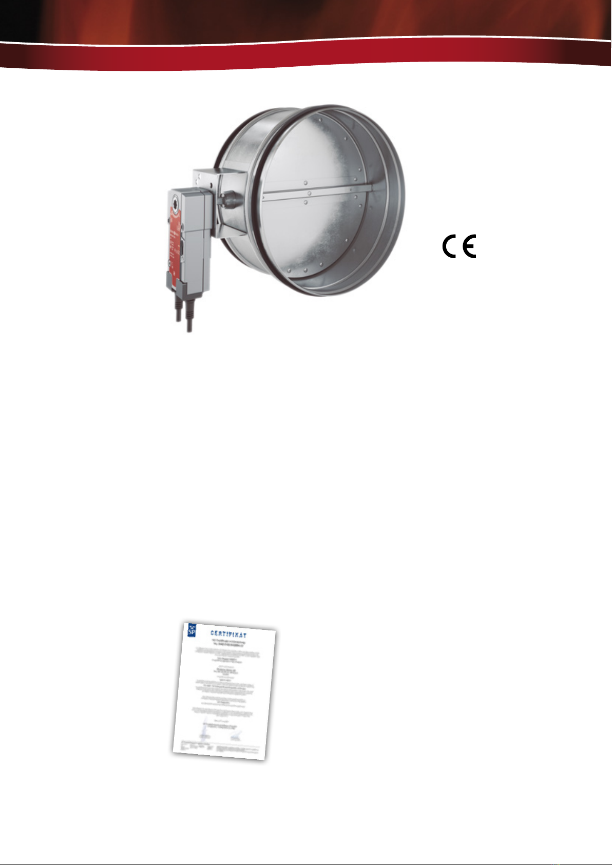
Fire damper RABC E60 / E120
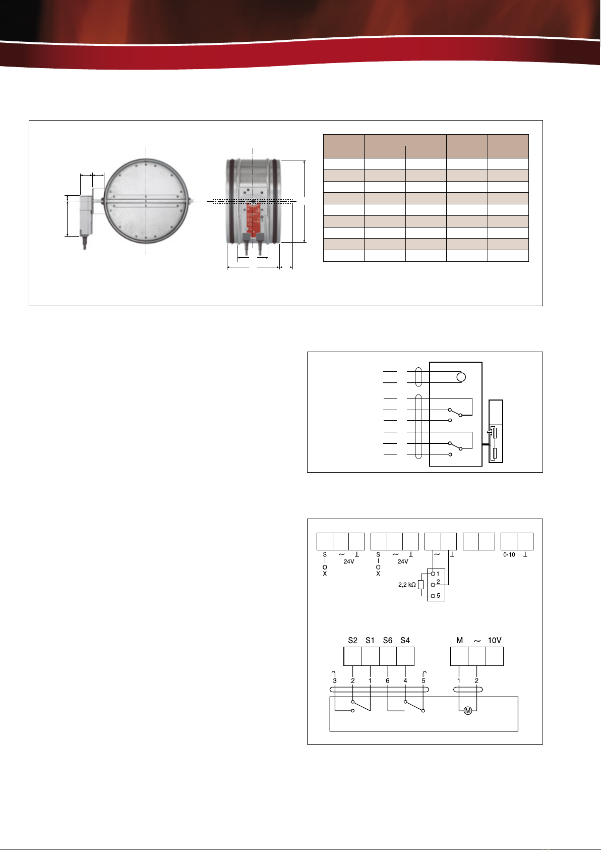
Installation
RABC is installed in horizontal or vertical ducts that pass
through fire cell separating building elements, according to
the adjoining installation instructions.
Actuator
RABC is always supplied with an electric safety actua-
tor with spring return complete with thermal sensor with
pushbutton for local manual operating test. The sensor
disconnects the power to the actuator if the temperature
exceeds 72°C inside or outside the damper. 24V actuators
are always used in connection with the MRB monitoring
system. Dampers can also be supplied with electric actua-
tor 230V.
Note that the RABC damper is always supplied with an
actuator.
Activation
According to Boverket’s Building Regulations smoke de-
tectors must be verified according to SS-EN 54-7 to acti-
vate dampers. The mandatory thermal sensor closes the
damper at 72 °C according to ISO 10294-4.
Control and monitoring
When the damper is used to prevent the spread of fire and
combustion gases it must be closed via impulses from the
smoke detector. This must be fitted in the ventilation duct
in the proximity of the damper or in another suitable loca-
tion. Smoke detectors are monitored by means of Rasch’s
MRB system or the like. The MRB monitoring system also
performs automatic operating checks on the damper every
48 hours and is designed so that faults are indicated im-
mediately and the damper closes.
See www.bevent-rasch.se for further details.
Quick facts
• Fire resistance class E60/E120S
• Sizes from 100 mm to 630 mm
• Prefitted safety actuator 24V or 230V
• Installation in ducts
• Available in MagiCAD
• CE-marked building product according to 15650:2010
Use
Damper in combination with walls or joist systems for
fire separation of heating, ventilation and air conditioning
installations in buildings. In accordance with the harmo-
nised European standard EN 15650:2010. In designs ac-
cording to associated documents, installation instructions
and when the damper is used in combination with smoke
detectors and monitoring system (MRB), or the like, the
spread of combustion gases is prevented. No further ac-
tion against the spread of combustion gases is required.
Performance
EC certificate according
to EN 15650:2010
402-CPD-SC0058-13
Classification of fire resistance
according to EN 13501-3
E120 (ve i <–> o) S*)
E120 (ve ho i <–> o)*)
E60 (ve ho i <–> o)
For complete classification,
see the Declaration of Performance.
*)Fire class E120 shall be specified when ordering.