Bradman Lake HS User manual

HS Former
- 1 -
MANUAL CONTENTS
1.0 ABOUT THIS MANUAL 4
1.1 Aftersales Support 5
2.0 INTRODUCTION 6
3.0 SAFETY FIRST 7
3.1 Put Safety First!!! 7
3.2 Local Safety aspects 7
3.3 Essential Do’s & Don’ts 8
3.4 Safety Rules 9
4.0 SPECIFICATIONS/DIMENSIONS 10
4.1 System Overview 10
4.2 Typical Machinery Layout 10
5.0 DESCRIPTION OF ASSEMBLIES 11
5.1 Plunger Slide Assembly 11
5.2 Plunger Head Assembly 11
5.3 Forming Head Assembly 12
5.4 Carton Feed Assembly 13
5.5 Feed Bar Ass’y & Feed Bar Drive Linkage 13
5.6 Vacuum Feed Assembly 13
5.7 Gate & Hopper Assembly 14
5.8 Drive Assembly 15
5.9 Drive Motor 15
5.10 Gearbox 16
5.11 Hand wheel 16
5.12 Drive Linkage 16
6.0 DESCRIPTION OF CONTROLS 16
6.1 Operator Interface 16
6.2 Logo Screen 17
6.3 Run Screen 18
6.4 Recipe Screen 19
6.5 Main Menu 20
6.6 Engineering Menu 21

HS Former
- 2 -
6.7 PLC Inputs Slot 1-2 22
6.8 PLC outputs Slot 3-4 22
6.9 Production Statistics 23
6.10 Current Alarm Screens 24
6.11 Alarm Statistics Screen 25
6.12 Machine Settings Screen 26
6.13 Changeover Screen 27
6.14 Setup Screen 1 28
6.15 Setup Screen 2 29
6.16 Main drive Speed 30
6.17 Clock Set Screen 31
7.0 OPERATING INSTRUCTIONS 32
7.1 Warning 32
7.2 Caution 32
7.3 Powering up the Machine 32
7.4 Pre-Start Checks 32
7.5 Starting the Machine 32
7.6 Jogging the Machine 33
7.7 Stopping the Machine 33
7.8 Turning Off the Main Supply 33
7.9 Safety Note 33
8.0 FAULT DIAGNOSIS/TROUBLESHOOTING 34
8.1 Troubleshooting 34
8.2 Vacuum System Diagnostic Chart 35
9.0 MACHINE ADJUSTMENT 36
9.1 Hopper Adjustment 36
9.2 Hopper Gate Frame Adjustment 37
9.3 Feed bar Adjustment 37
9.4 Plunger Adjustment 38
10.0 ROUTINE MAINTENANCE/CLEANING 39
10.1 Cleaning 39
10.2 Maintenance Schedule 39-40
10.3 Recommended Lubricants 41
11.0 INSTALLATION OF CHANGE PARTS 42
11.1 To Install A Forming Tool 42
11.2 To Install & Center The Plunger 42
11.3 To Set Corner Folders 43
11.4 To Set The Carton Blank To The Forming Tool & Plunger 43

HS Former
- 3 -
11.5 To Fit To The Frame Gate 44
11.6 To Fit The Hopper Back Plate 44
11.7 To Fit The Agitator Rods 44
11.8 To Fit The Guide Rods 44
11.9 To Change The Vacuum Cup Assembly & Feed Bar 44
11.10 To Renew The Vacuum Cups 45
11.11 To Change The Plunger & Forming Tools 45
11.12 To Change The Hopper Gate 46
12.0 GUIDELINES FOR CARTONS 47
12.1 Introduction 47
12.2 Manufacture Of Top Load Cartons 47
12.3 Handling & Storage Of Cartons 48-49
12.4 Packing Carton Blanks For Transit 50
APPENDIX
Recommended Spares List
Mechanical Assembly Drawings
Electrical Schematics

HS Former
- 4 -
1.0 - ABOUT THIS MANUAL
CONTINUOUS IMPROVEMENT POLICY
Bradman-Lake, Inc has a policy of continual research and improvement and we reserve the
right to make such modifications and design changes as are considered necessary in the
light of experience. For this reason illustrations and particulars given in this Manual may differ
in detail from machines in current production.
This manual is designed to help operators, maintenance personnel and engineers get the
best from the packaging machine.
Note: Please ensure that all operators and engineers read this manual in
its entirety before using the machine. Following the operating and
maintenance instructions will keep the machine operating at its maximum
efficiency and prolong its life.
The manual provides information on:
Routine maintenance
Machine operation
Safety
Cleaning
Troubleshooting
Changeover
The manual also gives a logical course of action and diagnosis for use in the event of a fault
occurring. The location and function of various components are illustrated and described to
enable personnel to understand and become familiar with the machine.

HS Former
- 5 -
1.1 AFTERSALES SUPPORT
Please call our dedicated Aftersales Team on: +1 704 588 3301
Or by e-mail: [email protected]
Our dedicated Aftersales Team exists to ensure that you get the best from your Bradman Lake
machine throughout its life. We aim is to ensure that your machine keeps running efficiently in
your production environment. We provide:
Spares Size Parts
Service Exchange Units Service & Support
Modifications & Upgrades Operator/Engineer Training
As the original machine manufacturer, we offer you the reassurance of expert service and
advice, providing the best solution to suit your needs.
Steve Privette
After sales Manager
Direct Dial: +1 704-940-1454
Mobile: +1 704-560-3277
E-mail: steve.privette@bradmanlake.com
Sarah Taylor
Spares Sales Engineer
Direct Dial: +1 704-940-1436
Mobile: : +1 704-661-1434
E-mail: bradmanlakespares@bradmanlake.com

HS Former
- 6 -
2.0 - INTRODUCTION
The Erector is an electrically operated, automatic, carton-erecting machine. It is powered
from an external 240 VAC supply and has a self-contained venturi vacuum system, which
forms part of the carton feed system.
Location of the machine relative to other equipment, such as conveyor systems, is assisted
by four wheels on the base of the cabinet. Jacking bolts near the wheels are used to stabilize
and level the machine after it has been positioned. An inclined hopper located at the back of
the machine is hand loaded with a stack of carton blanks. The feed system lifts them one at
a time from the end of the stack and places them on a forming tool ready for the erecting
operation. The hopper can be safely refilled without the need to stop the machine.
Mechanically agitated support rods in the hopper, acting in conjunction with a gravity
operated stack pusher, ensures consistent movement of the blanks along the hopper
towards the feed mechanism.
The forming head, onto which the carton blanks are fed, is mounted behind hinged guard
doors on the front of the machine. The forming head remains stationary while a sliding
plunger slides vertically through it, pushing the blank through the tool and folding it to form
the erected carton. The machine can be fitted with dedicated forming tools to produce
different sizes and / or styles of cartons.
Vacuum cups, mounted on a feed bar assembly and connected to the venturi vacuum
generator, grip each carton blank as it reaches the gate in the hopper and transfers it onto
the forming tool. A cam operated valve then vents vacuum system, releasing the carton
blank and the feed bar assembly then returns to the hopper gate to pick up the next carton
blank.
The electrical system components are housed in an enclosure mounted on one side of the
machine. Access to the enclosure is provided by a hinged panel fitted with an isolator switch
which interrupts power to the machine when the panel is unlocked. This is a safety feature
that ensures that the electrical supplies are isolated whenever the panel is opened. The
machine controls and an operator interface keypad are mounted on the side of the erector.
Mechanical safety switches are fitted to the transparent polycarbonate guards on the front of
the machine. If a guard is opened when the machine is operating, the electrical supply to the
motor is switched off and the motor brake is applied.

HS Former
- 7 -
3.0 - SAFETY FIRST
3.1 - PUT SAFETY FIRST:
The machinery described in this manual has been designed for the sole purpose of
packaging the specified product. Any other products must be approved beforehand by
Bradman-Lake Inc. Packaging of unsuitable products could result in damage to the
machinery and injury to the operator.
Suitable doors, guards and electrical safety devices are fitted to all Bradman-Lake
machines. These protective features are designed for the safety of the operator and are
tested in our plant before the machine is shipped.
The design of the guards and safety devices all follow the recommendations of OSHA and
satisfy the requirements of the Machinery Directive. The functions of the components must
not be altered in any way and they must not be replaced by alternative items.
3.2 - SAFETY ASPECTS OF LOCAL OPERATING INSTRUCTIONS:
Before delivery of your machine, prepare general operating instructions for the use of the
machine. The operating instructions must meet any requirements for:
Compliance with local safety regulations and codes.
Protection of employees against bodily injury, e.g. hard hats, gloves, safety glasses,
hearing protection etc. as required for local conditions.
Protection of employees against hazards such as hot surfaces etc.
Maintaining clear visibility of DANGER, WARNING and CAUTION notices and
labels.
Advisory indicating systems to alert employees near the machine that it is ready to
be started.
Piping all vents on pressure equipment to a safe location.

HS Former
- 8 -
Instructing operators how to deal with any foreseeable mishandling of the machine.
Although Bradman-Lake tries to guard against every possible misuse of the machine, there
are some circumstances where additional warning labels may be needed. Pinch Point
warning labels are positioned on the machine to warn operators/engineers of areas of
concern where fingers may get caught if misused. These are warning labels and therefore
must be kept visible at all times and must not be removed.
3.3 - ESSENTIAL DO’S AND DON’TS FOR SAFETY:
DO NOT operate the machine unless all guards are securely and correctly fitted.
DO NOT put your hands or fingers into the machine when it is running. If debris
needs removing ALWAYS stop the machine and open a guard door before
removing any obstructions.
DO NOT obstruct or remove any DANGER, WARNING or CAUTION notices /
labels that may be on the machine.
DO NOT use the machine if you have not received the necessary training.
DO check the security of all nuts and bolts, screws etc. After the machine has been
operating for a while.
DO keep the area around the machine clean and tidy.
DO disconnect any power supply when needing to work on the electrical system or
when cleaning the machine.
DO MAKE SURE YOU ARE AWARE OF WARNING SIGNS AND THEIR PURPOSE

HS Former
- 9 -
3.4 SAFETY RULES:
No one should operate this equipment unless they have read the service manual
and have been instructed on safety and operation of the machine.
All guards must be in their proper place before starting machine.
The operator should look to insure that the machine is clear before start-up, and
call a warning, “CLEAR”, to alert other personnel that the machine is being
started.
Do not reach into the machine until it has come to a complete stop.
Activate an EMERGENCY STOP prior to clearing jams and reaching into the
machine.
Turn the main power disconnects OFF and attach a padlock to assure that the
power to the machine remains OFF when performing maintenance on the machine.
Do not wear loose clothing or jewelry when operating this machine.
Personnel should be familiar with the location and function of the EMERGENCY
STOP SWITCHES on the machine.
GENERAL SAFETY INFORMATION
This machine has been guarded for the safety of all personnel that are involved with the
production process through the machine. When operating this equipment, all guards must be
in place. Guards, safety switches, and interlocks should not be bypassed for any reason.
Any change or modification to the safety equipment of this machine may produce a
hazardous condition that could cause injury to persons working with the machine. Electrical
cabinets and boxes should not be opened unless power has been disconnected.
WARNING: DISCONNECTING OR BYPASSING THIS MACHINE’S
SAFETY EQUIPMENT WILL VOID THE MANUFACTURER’S
WARRANTY.

HS Former
- 10 -
4.0 SPECIFICATIONS/DIMENSIONS
4.1 SYSTEM OVERVIEW
The HS Former is an electrically operated, automatic, carton erecting machine. It is powered
from an external power supply and has a self-contained vacuum system which forms part of
the carton feed system. The machine is designed to form cartons or trays from a supply of
specially profiled, flat, carton blanks.
Carton blanks are manually loaded into the Inclined Hopper in a vertical format. The blanks
are individually picked by vacuum cups on the Feed Bar, and placed onto the dedicated
Forming Tool for that specific product. The Plunger then descends, driving the carton blank
thru the Forming Tool causing the side flaps to be plowed, locked and closed. The Forming
Head continues to descend, finally discharging the formed carton onto a Product Conveyor.
The system uses a carton make on demand Photocell to control the formed carton supply to
the downstream conveyors.
4.2 TYPICAL MACHINERY LAYOUT
Figure 4.1- Machine Dimensions
Optional Vacuum Pump
HS Former
- 11 -
5.0 - DESCRIPTION OF ASSEMBLIES
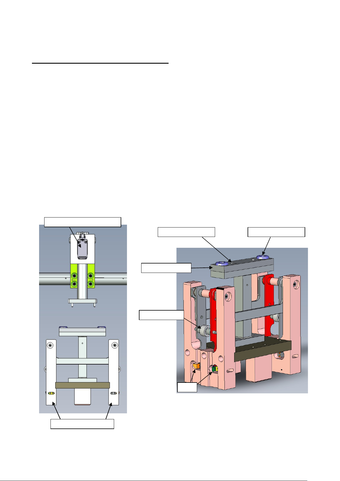
5.1 - PLUNGER SLIDE ASSEMBLY:
The plunger slide assembly comprises of two interconnected plunger slide castings, each
having an upper and lower bearing block bolted to it. The bearing blocks slide vertically on
two fixed pillars, one either side of the cabinet. A split clamp, integral with each plunger slide
casting, grips a transverse cross bar to which the plunger head mounting brackets are
attached again by an integral split clamp. An aligning plate is attached to the plunger head
mounting bracket and the plunger head assembly is secured to the aligning plate.
Grease nipples are fitted to the bearing blocks for routine lubrication. If it becomes necessary
to renew the bushes in the bearing blocks, this must be done without removing the bearing
blocks from the slide casting.
5.2 - PLUNGER HEAD ASSEMBLY:
This carries the forming block about which the carton is erected and is unique to each carton
size. The assembly is hung from the plunger mounting bracket.
The plunger head is a ' Change part ' and a component of the forming tool assembly.
TIP’S
ALIGNMENT SCREW
B
ALIGNMENT SCREW A
ALIGNMENT PLATE
CAM FOLLOWER
TIP ADJUSTING SCREWS
PLUNGER OVERLOAD SENSOR

HS Former
- 12 -
5.3 - FORMING HEAD ASSEMBLY:
This assembly forms the ' die ' which shapes the carton. It is mounted across the front of the
former, directly below the plunger head. Four curved plates form a rectangular aperture
conforming to the outside of the erected carton. The upper horizontal surfaces act as a
platform for the carton blank. Register pins locate the carton blank accurately in position. The
complete assembly is a ' Change part '.
STRIPPER SPRING STRIPPER FINGERS
SPRING HOOK
CROSSBAR SPRING
REGISTER PINS
REAR FORMING PLATE
FRONT FORMING PLATE
CROSS BAR ASSEMBLY
CROSS BAR ADJUSTER
RETAINING BOLT
HS Former
- 13 -
5.4 - CARTON FEED ASSEMBLY:
Two feed arms are mounted on the oscillating feed shaft. The feed shaft is driven by the
adjustable link connected to the pivot shaft. At the end of each feed arm is a pivoting block.
These two pivot blocks carry the square section feed bar assembly.
Two round section guide rods are freely suspended from fixed points either side of the
machine. Each rod is a sliding fit in a hole bored through their operating arc, the guide rods
cause the pivot blocks ( and feed bar assembly ) to rotate. This ensures that at each end of
the stroke the vacuum cups are presented at the correct angle to the hopper gate, or forming
head as appropriate. Vacuum control is via the encoder signal timing setting on the HMI to
control the suction cups. Suction is applied as the cups approach the carton blank in the
hopper gate and cut off when the carton is placed over the forming tool. The position of the
cam on the shaft is adjustable.
5.5 - FEED BAR ASSEMBLY & feed bar drive linkage:
The feed bar is the square section bar fastened to the two pivot blocks.
Clamped to this bar are the two suction cup arms. Positioning and clamping of the cup arms
is part of the initial setting up procedure. Once set, the feed bar assembly is dedicated to that
particular carton and is therefore regarded as a ' change part '.
The feed bar drive linkage has two adjustments, one to position the feed bar relative to the
hopper gate, the other to alter the length of the stroke. Feed bar position is adjusted by
unlocking and turning the link rod to alter the length of the rod. Stroke length is altered by
loosening the nut and bolt at the lower end of the link and sliding the bolt along the slot in the
drive shaft lever to shorten or lengthen the effective arc of the lever.
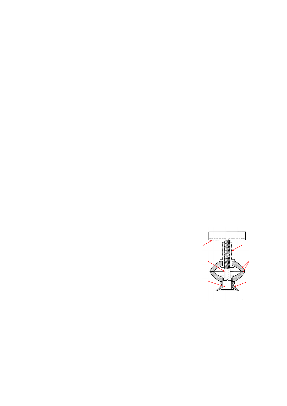
5.6 - VACUUM FEED SYSTEM:
The vacuum is generated by an electrical vacuum pump or an
air driven venturi pump. This vacuum operates through the
suction cups on the feed bar via a valve trigger by encoder
settings set on the HMI.
TEE PIECE
BL 054
BELLOWS SCREW
BL 039
BELLOWS
SLEEVE
BL 051
BELLOWS
CONNECTOR
BL 052
BELLOWS CUP
VCC0050
VACUUM CUP
VCC0051
VACUUM CUP ARRANGEMENT
HS Former
- 14 -
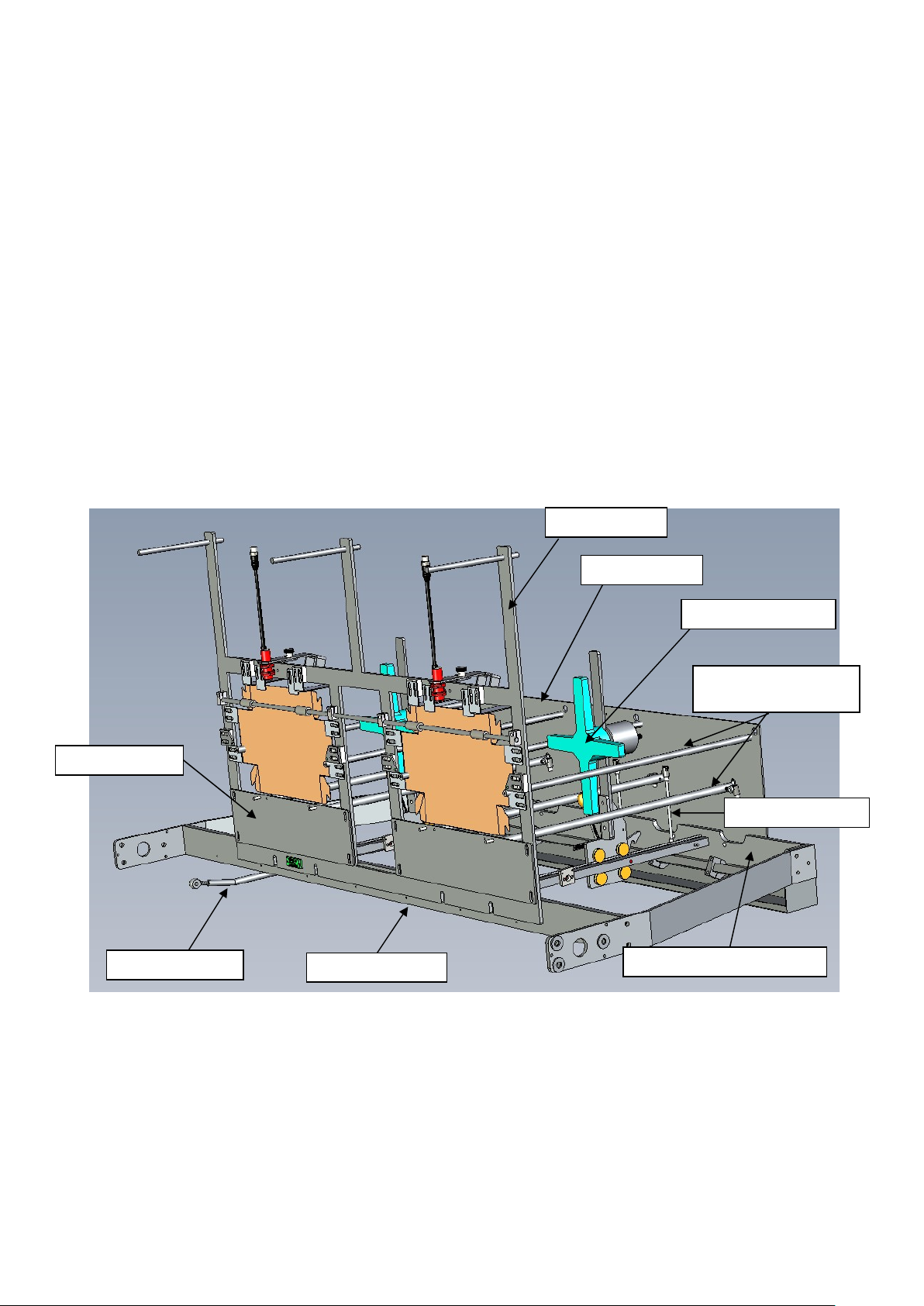
5.7 - GATE AND HOPPER ASSEMBLY:
This assembly comprises of a gate frame secured to a transverse mounting bar at the rear of
the machine, adjacent to the feed shaft. From the gate frame, rods extend rearwards to the
hopper back plate, which is mounted on a hopper support bar. These rods provide support
and guidance for the carton stack. There is a central bar parallel to the carton stack which
acts as a rail for the sliding stack pusher. The hopper assembly is inclined at an angle and
the stack pusher being weighted acts upon the carton stack to ensure an even and constant
presentation of carton blanks to the suction cups.
The hopper is fitted with a photo-sensor which stops the machine when the carton stack gets
to low and needs replenishing. The stack guide is fitted with a clamping knob to lock it to the
rear when fresh carton blanks are being loaded. Adjustable tabs are provided on the gate
frame to act as supports for the carton blanks. The two lower rods on which the stack rest are
connected to agitator links which oscillate to ensure an even and constant presentation of
cartons and is driven from the feed shaft. The gate frame, back plate and agitator links are all
' Change parts '.
DOUBLE GATE ASSEMBLY
GATE FRAME
BACK PLATE
HOPPER SUPPORT BAR
AGITATOR BAR
AGITATOR LINK
MOUNTING BAR
SIDE AND BOTTOM
HOPPER ROD
FRONT PLATE
CARTON PUSHER
HS Former
- 15 -
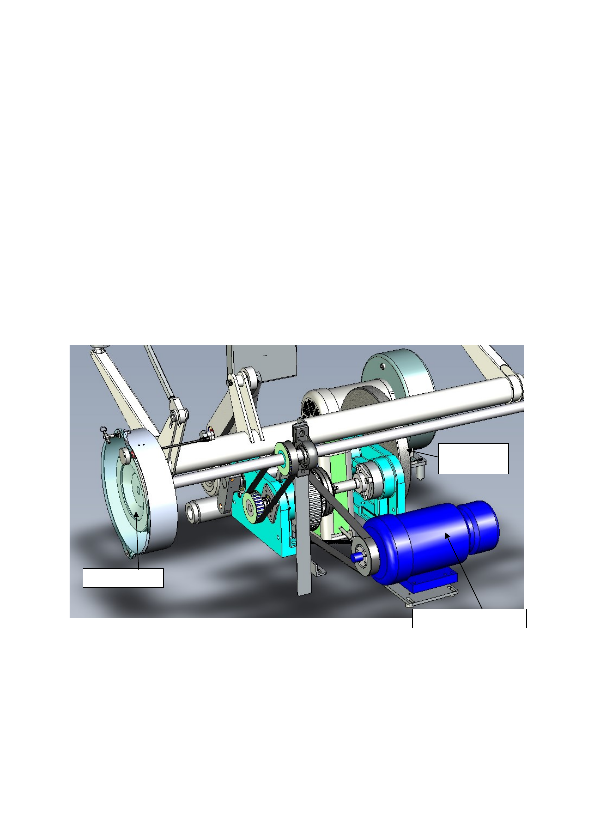
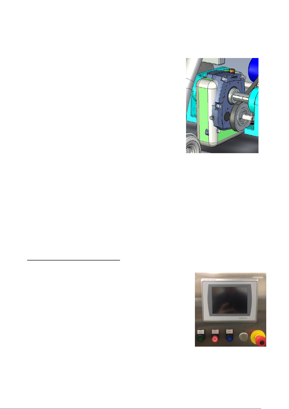
5.8- DRIVE ASSEMBLY
The drive unit consists of an AC motor mounted on a slide base. The motor drives the torque
limiter shaft by means of a timing belt on the motor shaft and a driven pulley on the torque
limiter shaft. A timing belt drive is taken to the Hand wheel shaft from the torque limiter shaft.
A timing belt drive is taken to the input shaft of the shaft mounted reduction gearbox. The
timing belt pulley on the torque limiter shaft is mounted in the torque limiter (slipping clutch
type) to protect the machine. This clutch should be set at a minimum torque value, such that
the machine will run with no signs of slippage. An adaptor bolted to the torque limiter hub
carries the pulley. The torque value is set by an adjuster nut, threaded onto the hub, which
acts against a disc spring to pre-load the friction linings against the pulley face.
The torque limiter shaft is supported at one end by a pillow block bearing mounted on a
mounting bracket. The mounting bracket can be removed to facilitate easy removal of the
timing belts.
The reduction gearbox is mounted on the main crankshaft. A flywheel is mounted on one
end of the main crankshaft to balance the drive. A sprocket is mounted to the crankshaft to
drive the Product Loading Conveyor and Top Loader
5.9- DRIVE MOTOR
The motor is a totally enclosed fan cooled unit fitted with an integral automatic brake, which is
spring loaded to stop the motor immediately when the electrical supply is terminated. While
the supply to the motor is uninterrupted, the brake is energized to the released position.
Manual release of the brake is provided by engaging the brake override key switch.
MAIN MOTOR DRIVE
HAND WHEEL
WEIGHTED
FLYWHEEL
HS Former
- 16 -
5.10- GEARBOX
The gearbox is of the shaft-mounted type. An anchor is fixed
to the main base frame to restrain the gearbox. The anchor
length is adjusted to give the correct tension to the timing belt
to the gearbox.
5.11- HANDWHEEL
The handwheel is at one end of the handwheel shaft and can be located on the outside of
the Former. A pulley on this shaft is connected via a timing belt, to the pulley on the torque
limiter hub. An arrow on the handwheel guard shows operating rotation. When clearing
jams, rotate handwheel in counter clockwise direction.
5.12 DRIVE LINKAGE
A crank arm keyed to the gearbox output shaft is linked by a connecting rod to an oscillating
pivot shaft. Two arms, one on either end of the shaft, carry the plunger links, which are
connected to the vertically moving plunger slide assemblies. Another link on the pivot shaft is
connected to the oscillating feed shaft, which in turn, carries the carton feed assembly. All
links are adjustable by means of threaded rod ends.
6.0- DESCRIPTION OF CONTROLS
6.1- OPERATOR INTERFACE
The Operator Interface consists of (4) Manual pushbuttons and
an Allen-Bradley PanelView Plus 700 Touchscreen.
1. Start - Starts machine after power is on & faults have
been cleared.
2. Stop- Stops machine; press Run to return to operation.
3. Reset- Resets machine after fault(s) are cleared.
4. E-Stop- Shuts down machine in safe mode; pull out to
reset for running.

HS Former
- 17 -
6.2 - LOGO SCREEN
This is the first screen that appears after the machine is powered up.
Figure 6.2.1- Logo Screen
Pushing Shut Down shuts down the machine. (This prompt is only visible if the engineering
password is used.)
HS Former
- 18 -
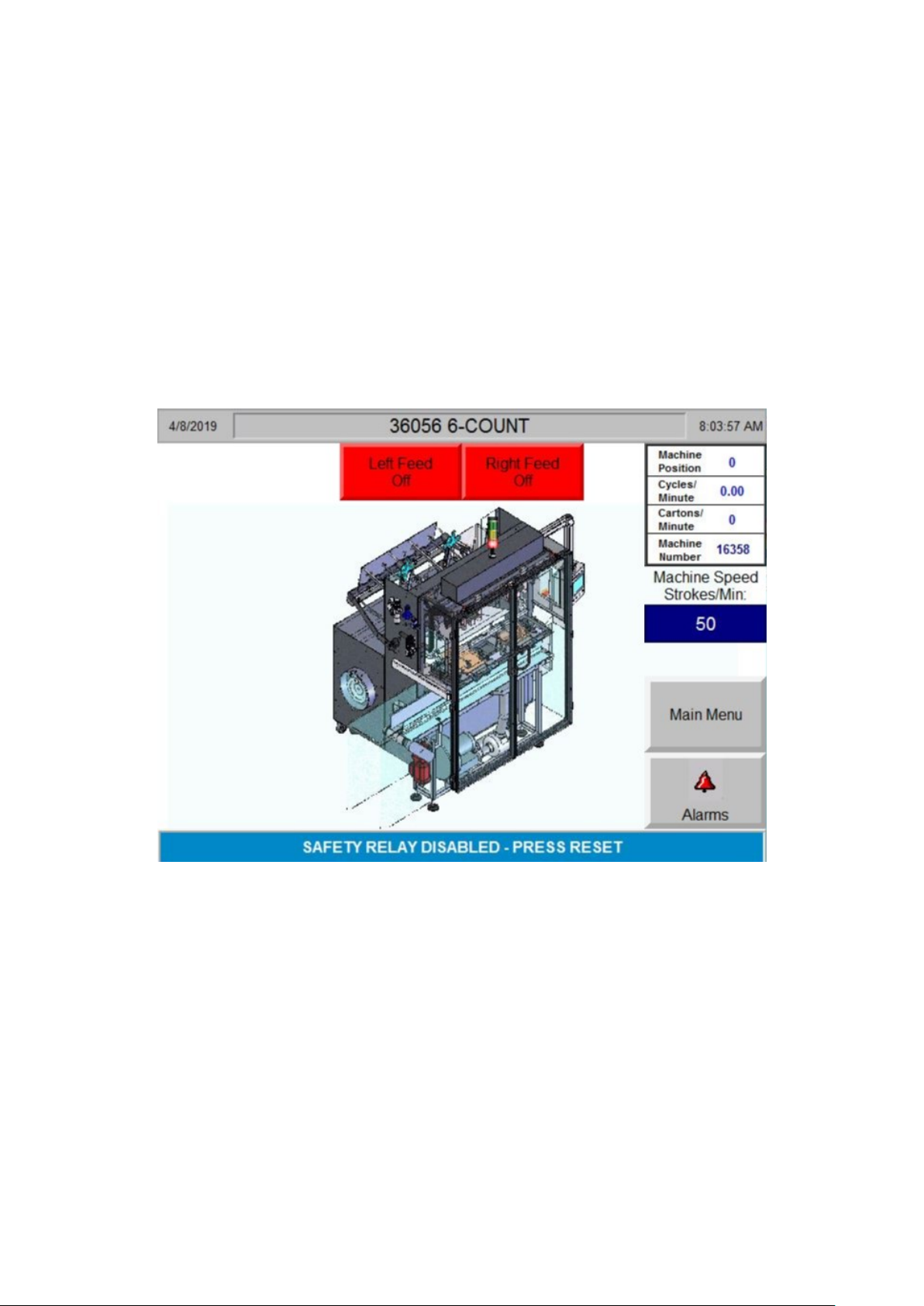
6.3 - RUN SCREEN
This screen provides an overview of the machine using a status bar and graphical
representation of certain faults i.e. an open guard door will alarm in the status bar and the
corresponding door will flash red and yellow on the machine graphic.
The status bar will indicate if the machine is ready to run, needs resetting or has a fault that
needs clearing.
Basic machine speed outputs are displayed for example cycles per minute and cartons per
minute are shown.
Figure 6.2.2- Run Screen
Use the following Function Buttons to bring up the respective screens:
1. Left Feed On/Off- Toggles the vacuum feed on that side.
2. Right Feed On/Off- Toggles the vacuum feed on that side.
3. Machine Speed- Displays the erecting rate in machine cycles/min.
4. Main Menu- Returns to the Main Menu.
5. Alarms- displays the alarms screen, from which you can access alarms statistics.
HS Former
- 19 -
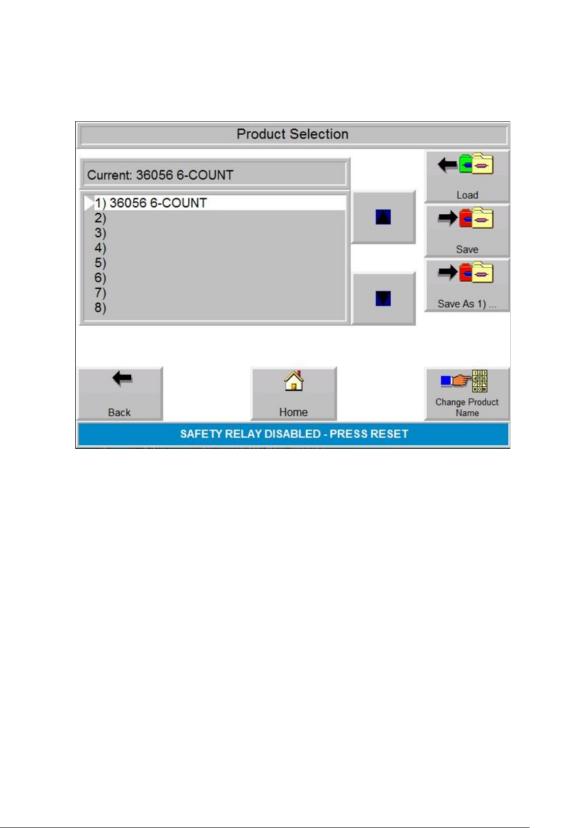
6.4 - RECIPE SCREEN
Figure 6.4.1 - Recipe Screen
The Recipe screen allows the operator or engineer to create, load and rename recipes
specific to individual products.
If you have a new product similar to an existing one, then you can modify the existing
program and save as thus reducing the amount of input to create a new product.
1. Back- Returns to the last screen (Run or Settings Screens).
2. Home- Displays the Run Screen.
3. Load- Loads the highlighted recipe into memory.
4. Save as- Copies the highlighted recipe settings to another recipe.
5. Change Product Name- Allows the user to change the name of the highlighted
recipe.
HS Former
- 20 -
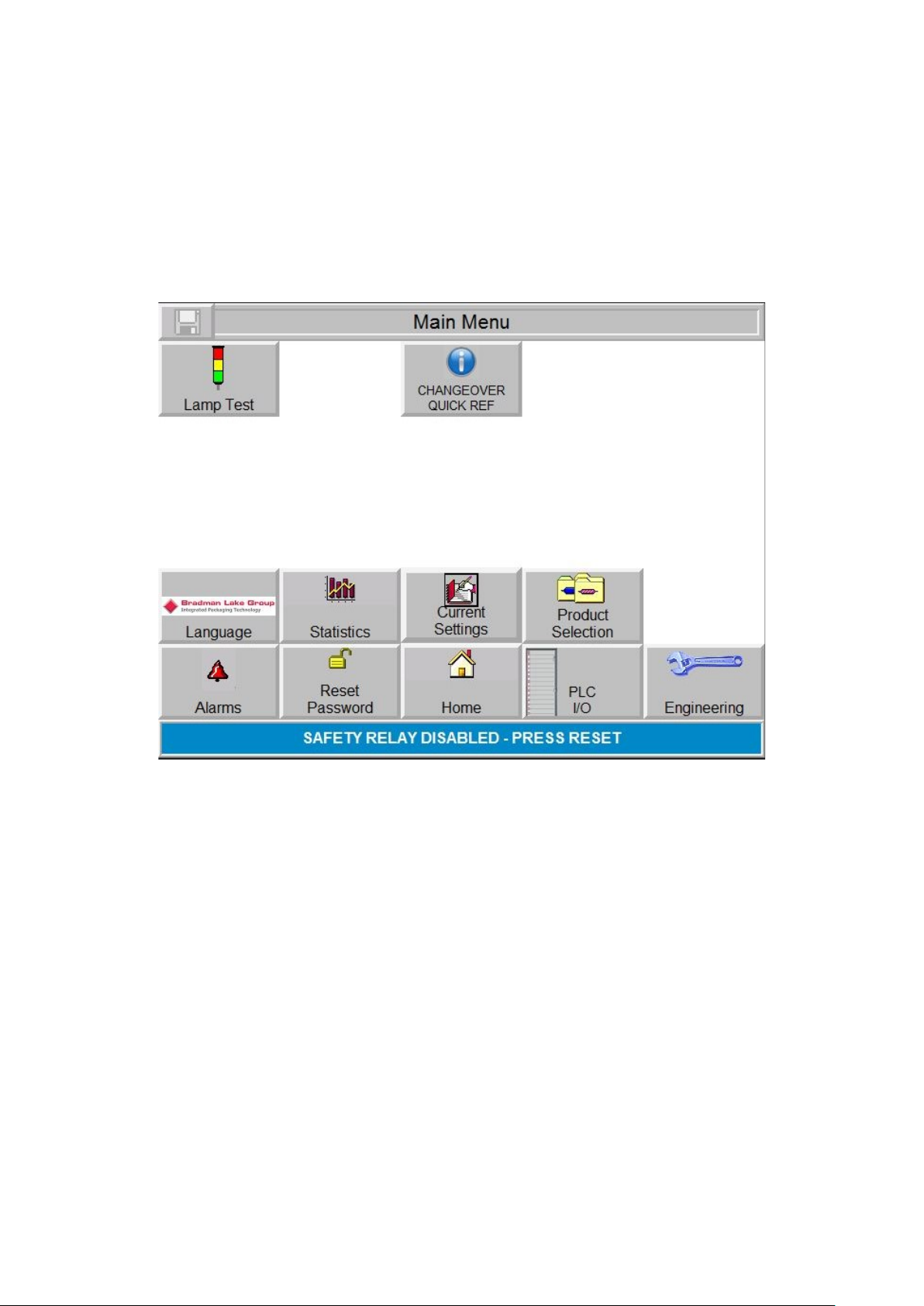
6.5 - MAIN MENU
The main menu screen is accessed from the Run screen. There are both operator and
engineer specific selections, engineering is usually password protected and may be
configured to have multiple levels of access.
6.5.1- Main Menu Screen
Figure 6.5.1- Main Menu Screen
Pushing the following functional buttons will access the indicated parameters:
1. Lamp Test- Tests the lamps for proper operation.
2. Machine Illumination- Turns on/off the machine lighting, if equipped.
3. Quick Changeover Ref- Displays the Changeover Screen.
4. Language- if multiple HMI translations are present then you can select here.
5. Statistics- Displays the Data Screen.
6. Product Selection-Displays the Product Selection Screen.
7. Alarms- Displays the Alarm Screens.
8. Password Reset- Allows the user to reset the password if the original is known.
9. Home- Displays the Run Screen.
10. Current Settings- this screen displays the current recipe settings, (display only)
11. Engineering- Displays the Engineering Menu.
12. PLC I/O- Displays a graph of all PLC inputs and outputs with real time on/off
illumination.
This manual suits for next models
1
Table of contents


