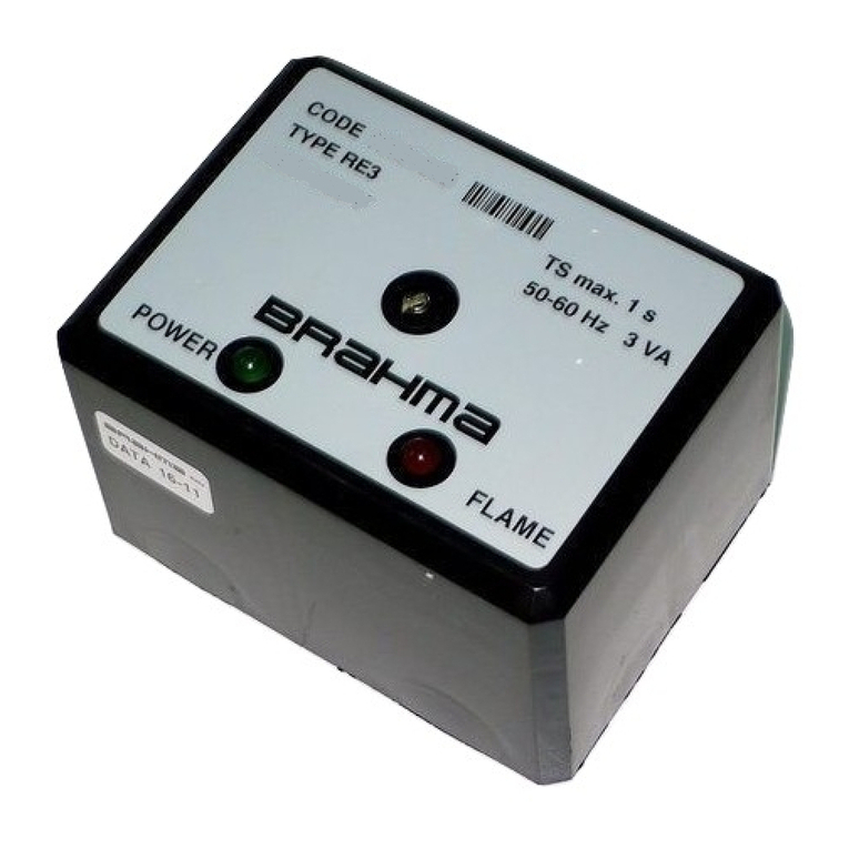
BRAHMA TC340 User manual

14698_r00 1/18
DIGITAL TEMPERATURE
ADJUSTMENT SYSTEMS
Type TC340
DIGITAL IGNITION AND FLAME CONTROL
SYSTEMS FOR HOT AIR GENERATORS (TYPE
TC340A – TC340P) AND FOR MODULATING
PREMIX BURNERS (TYPE TC340P1)
DESCRIPTION
These systems are specifically designed for safety cycle control
and temperature adjustment in hot air generators equipped with
automatic-ignition fan-assisted gas burners and in modulating
premix burners.
GENERAL FEATURES
The systems are provided with the following important features:
− compliance with EN 298:2003-09 (European standard for
automatic gas burner control and flame monitoring systems);
− CE approval according to Gas Appliance Directive 90/396/EEC
and following amendments (Directive 93/68/EEC);
− suitable for both phase-phase and phase-neutral power supply
systems;
− non-polarized flame signal amplifier (the power supply polarity
may not be respected even in case of a phase-phase power
supply network);
− control of the hot air convector blower (FAN) by means of a
phase-cut driver;
− control of the burner motor by means of a phase-cut driver (for
fan-assisted gas burner appliances) or through a PWM signal
(for premix gas burner appliances equipped with brushless fan
with integrated management electronics);
− two independent safety contacts for driving the EV1 main
solenoid gas valve;
− inbuilt capacitive-discharge ignition transformer (version for fan-
assisted appliances);
− output for the control of an auxiliary electronic ignition
transformer;
− prearranged for the control of the EV2 second valve stage by
means of two independent contacts taking the power supply
from the EV1 first valve stage (version for fan-assisted
appliances);
− burner power modulation by means of a current modulator
(version for fan-assisted appliances) or through a PWM signal
(version for premix appliances);
− possible interfacing with a BRAHMA digital chronothermostat
type ENCRONO GA1 through OpenTherm™ communication
protocol, or with a power-free contact room thermostat;
− possible interfacing with additional TC340 devices for
“cascade" applications (OpenTherm™ communication
protocol);
− summer ventilation function (only in connection with BRAHMA
chronothermostat type ENCRONO GA1);
− control of a BRAHMA double NTC temperature probe type
ST16 with outlet air temperature adjustment and safety
functions;
− control of a BRAHMA double NTC temperature probe type
ST08 with outlet air temperature adjustment functions;
− possible control of a safety thermostat;
− prearranged to control a BRAHMA NTC temperature probe
type ST07 with room or outside temperature adjustment
functions;
− possible connection to a fire damper contact (optional);
− possible application in modulating premix burners equipped
with three-point adjuster or adjustment thermostat;
− possible application in appliances provided with 0÷10V
analogue signal adjustment (e.g. PLC);
− on-board manual reset push-button;
− operation status and failure signalling by a two-colour LED;

2/18 14698_r00
− prearranged for the remote connection of the manual reset and
status displaying signals through a BRAHMA module type 865
(containing a two-colour LED and a reset push-button);
− communication interface type RS-232 for diagnostic and set-up
functions (through BRAHMA serial interface type 810 and
management software);
− inbuilt EMC filter;
− two fuses provided with removing tool to protect the power
supply network on both potentials;
− connections for on-board safety earthing.
TECHNICAL DATA
Nominal supply voltage: 220÷240V
AC
@ 50/60 Hz
Power consumption: 20 VA
Operating temperature range: -20 °C ÷+60 °C
Humidity: 95% max. @ +40 °C
Protection rating: IP00
IP40 with box (upon
request)
Internal fuse rating: 6.3 A slow-blow
for TC340P1:
3.15 A slow-blow
External fuse rating (recommended): 6.3 A fast-blow
1
for TC340P1:
3.15 A slow-blow
1
Max. total weight: 250 gr. approx.
EC type certificate: CE0051-PIN0051BU3887
NOTES
1)
The external protection fuse rating should be selected considering the max.
load consumption in the most unfavourable operation stage and conditions.
Classification codes according to EN 298:
TC340A.**.** F T C L X N
TC340A.**.** opt. V F T L L X N
TC340A.**.** opt. E F T C V X N
TC340A.**.** opt. V E F T V V X N
TC340P.**.** F M C L X N
TC340P.**.** opt. V F M L L X N
TC340P.**.** opt. E F M C V X N
TC340P.**.** opt. V E F M V V X N
Times:
Pre-purge time (TP): 0 … 60 s
Safety time (TS): 3 … 120 s
Response time in case of flame failure: < 1 s
Post-purge times
- on burner motor (EF) (t
POST
):
- on hot air blower (FAN) (t
FS
):
2
0 … 1200 s
0 … 1200 s
Delay time on FAN activation (t
FA
):
2
0 … 1200 s
Inter-waiting or inter-purge time: 1 … 240 s
Waiting time for modulation start (t
RP1
): 1 … 240 s
Lockout delay for extraneous light (opt.
Knn): 0 … 60 s
Lockout for insufficient air flow (opt.
Qnn)
3
: 3 … 120 s
Pre-ignition time (opt. Jnn): 1 … 60 s
Recycling attempts (opt. Ynn): 1 … 10
Varnishing / Box: upon request
NOTES
2)
This parameter will be described in detail in the “Heating mode (FAN
function)” section. It can be modified through BRAHMA serial interface type
810 and management software.
3)
If the air pressure switch remains in “no-air-flow” position (fan-assisted
versions) or if the burner motor revolutions per minute are insufficient in
case a brushless fan is used (premix versions).
4)
This parameter can be modified through BRAHMA serial interface type 810
and management software.
Max. contact rating (@ 240V - 50Hz):
Hot air blower (FAN): 3.5 A cos ϕ≥0.4
Burner motor (EF): 0.5 A cos ϕ≥0.4
Remote ignition device (ACC1): 0.8 A cos ϕ≥0.4
First valve stage (EV1): 0.4 A cos ϕ≥0.4
6
Second valve stage (EV2): 0.4 A cos ϕ≥0.4
6
Current modulator:
≤170 mA
DC
@ 24 V
DC 5
NOTES
5)
The limit can be increased up to 350mA upon request.
6)
The valve load power supply is available on two independent connectors
(J7 and J8). In case both connectors are used, the max. rating for each
output should be considered equal to 0.2 A cos ϕ≥0.4 approx.
Max. cable length for external components:
OpenTherm™ interfaces: 50 m
Ignition device (high voltage cables): 2 m
Any other cable (load power supply cables, user
interface connection cable, …): 1 m
Inbuilt ignition transformer (ACC2):
7
Peak voltage:
8
upon request:
15 kV
18 kV
Peak current: 800 mA
Spark repetition rate:
9
upon request:
25 Hz
1 … 50 Hz
Recommended spark gap: 2 ÷ 4 mm
Power consumption: 2.5 VA
Spark energy: 20 mJ
NOTES
7)
For appliances equipped with fan-assisted burner only.
8)
Value measured with 30 pF load.
9)
ATTENTION: the ignition device output is not safe to touch if the spark
repetition rate is higher than 25Hz; in this case the appliance will have to
be provided with further protection.
Flame monitoring
The flame detection device exploits the rectification property of the
flame.
An important safety aspect to note is that the control unit is more
flame-sensitive at start-up or during the waiting/pre-purge time
(negative differential switching).
Min. ionization current: upon request:
0.5 µA
1.2 µA
Recommended ionization current: 3 ÷ 5 times the
min. one
Min. insulation resistance of detection
cable and electrode to earth: ≥50 MΩ
Max. electrode stray capacitance: ≤1nF
Max. short-circuit current: < 200µA
AC
System adjustment temperatures:
Manual reset limit temperature (T
L
):
10
100 °C
Switch-off temperature (T
OFF
):
11
70 °C
Re-ignition temperature (T
ON
):
11
50 °C
Ventilation temperature (T
V
):
11
30 °C
Ventilation-stop temperature (T
SV
):
11
10 °C
NOTES
10)
Available in versions using BRAHMA safety probe type ST16.
11)
This parameter can be set up on customer's request and modified through
BRAHMA serial interface type 810 and management software.

14698_r00 3/18
System temperature probes
The BRAHMA system type TC340 is provided with several inputs
to control different temperature probes used for both temperature
adjustment and safety related functions. The characteristics and
functions of each probe are described in detail below.
- Heating circuit probe (SR)
The heating circuit probe has the purpose to measure the heat
exchanger temperature and is mainly used in the FAN heating
function (see description in “OPERATION” section).
This probe can be of three types:
1) with double NTC sensor (standard version): in this case the
probe has a double function, as it enables to avoid mounting a
safety limit thermostat. This probe will therefore be used for
both temperature adjustment and safety functions (e.g. safety
shutdown due to system overtemperature).
To this purpose, a BRAHMA temperature probe type ST16 is
required.
J10
BRAHMA
type
ST16
BROWN
BLACK
BLUE
Fig. 1 – Connection of a double NTC probe
2) with single NTC sensor with contact safety thermostat (opt. T)
:
in this case the probe is provided with temperature adjustment
functions only, and any system overtemperature will have to be
controlled by a contact safety limit thermostat.
To this purpose, a BRAHMA temperature probe type ST08 is
required.
J10
BRAHMA
type
ST08
Safety limit
thermostat
Fig. 2 - Connection of a single NTC probe
3) with single NTC sensor without contact safety thermostat (opt.
NT)
: in this case the probe is provided with temperature
adjustment functions only, and any system overtemperature will
have to be controlled by an external safety device.
To this purpose, a BRAHMA temperature probe type ST08 is
required.
- Room temperature probe (SA)
This (optional) probe can be used when the remote temperature
adjuster (BRAHMA chronothermostat type ENCRONO GA1) is not
directly mounted in the room requiring temperature adjustment, or
when this temperature adjustment should be related to the external
environment temperature. For further details about the functions of
this probe, please see the
"OPERATION"
section.
To this purpose, a BRAHMA temperature probe type ST07 (for
local room temperature detection) or type SSE (for outside
temperature detection) is required.
Fire damper (STF)
This input (option S) enables to check the status of the fire damper
contact: in case this contact is open (anomaly condition), the
ignition cycle is interrupted and the device goes to stand-by
position signalling the failure through a LED. The behaviour of the
device in case the fire damper contact is open can be customized
upon request.
Overall dimensions
Fig. 3 shows the overall dimensions of this type of control units. All
dimensions are expressed in millimetres.
Fig. 3 – Overall dimensions
INSTALLATION DIRECTIONS
−
Respect the applicable national and European standards
regarding electrical safety (e.g. EN 60335-1/ EN 50165),
bearing in mind that ignition and flame control systems are
safety devices: the manufacturer's responsibility and guarantee
are invalidated in case of Customer's tampering with the
product;
−
before the first start-up, make sure that the loads are well
connected to avoid any dangerous situation or failure in the
appliance. Particular attention should be paid to earth
connections: make sure that all loads (fans, gas solenoid
valves, ignition transformer, …) are connected to the appliance
safety earth, using for example the connector on board;
−
the system is designed to stay in running status for less than
24h (system for non-permanent operation). Reaching this limit
causes a regulation shutdown to enable the unit to check its
own efficiency;
−
connect and disconnect the control unit only after switching off
the power supply;
−
the unit can be mounted in any position;
−
avoid exposure to dripping water;
−
a ventilated installation environment and a suitably low
temperature ensure the longest life of the control system;
−
before installing or replacing the unit, make sure that the type,
code and times are correct;
−
the appliance in which the control systems are installed should
provide adequate protection against the risk of electric shock
(at least IP20);
−
keep signal cables and power cables as far from each other as
possible;
−
use heat resistant detection cables and electrodes, and make
sure that they are well insulated to the ground and protected
from possible moisture or water in general;
−
keep the ignition cable as short and straight as possible and
place it far from other conductors to reduce the emission of
electromagnetic interference (max. length <2m and insulation
voltage >25kV).
71
65
67,5
Ø4
145
136
145
60
80,1
40
TWO-
COLOUR
LED
RESET
P/BUTTON

4/18 14698_r00
!
!!
!
IMPORTANT NOTE
In order to further reduce irradiated interference and increase the immunity of the
control unit, it is strongly recommended to mount a wire-wound power resistor with
a value from 1kΩto 4.7kΩbetween the high voltage cables and the related
discharge electrodes.
CHECKING AT START-UP
Check the control system before the first start-up, after any
overhaul and after a long period of non-operation. Before any
ignition attempt make sure that the combustion chamber is free
from gas, then check the following:
−
if the start-up attempt occurs without gas supply, the control
system should go to lockout at the end of the safety time;
−
when stopping the gas flow while the control system is running,
the power supply to the gas valves should be interrupted within
1s, and the control system should proceed to lockout after a
recycling attempt (or more than one up to 10 depending on the
settings);
−
operating times and sequence should correspond to those
declared for the type of control unit you are using;
−
the level of the flame signal should be high enough (see Fig. 4);
−
the ignition probes should be adjusted in the most stable way
for a spark gap between 2-4 mm;
−
the intervention of limiters or safety devices should cause the
lockout or safety shutdown of the control unit according to the
type of application and the procedure provided for.
Microammeter
A
+
-
J2
I
ION
Fig. 4 – Flame signal measuring method
TC340(A-P) - OPERATION
The following description refers to the standard operating cycle of
BRAHMA control units type TC340A and TC340P. The operating
cycle can be modified both using the available options and
according to particular customer's requirements.
- First start-up
At the first start-up, the device carries out a “
self-test
” to verify that
all the conditions required at the beginning of the ignition cycle are
respected.
At the end of this stage, the system goes on checking the type of
heat demand used in the appliance (power-free contact or
OpenTherm™ connection to BRAHMA chronothermostat type
ENCRONO GA1 or to an additional TC340 unit): in this stage,
lasting about 30 seconds, the SL LED signal flashes with green
light indicating the stand-by status.
At the end of this diagnostic phase, the unit is ready to receive the
heat demand and start the ignition cycle.
- Ignition cycle
The ignition and flame control cycle starts on receipt of the heat
demand, which can occur in three ways:
-
through a BRAHMA chronothermostat type ENCRONO GA1;
-
through a power-free contact with room thermostat function;
-
through an additional BRAHMA device type TC340 in case of
cascade systems.
The control unit starts the ignition cycle by checking the air
pressure switch status (fan-assisted version) or the number of
revolutions per minute of the EF burner motor (premix version). In
case no signal is detected, the system starts the EF fume extractor
at its max. speed; as soon as the air pressure switch goes to “air-
flow” position (fan-assisted version) or the necessary number of
revolutions per minute is reached (premix version), the pre-purge
time (TP) begins.
In premix applications, a few seconds before the beginning of the
safety time (about 3 seconds, customizable upon request), the
system reaches a stage of the pre-purge time in which the EF
combustion motor speed can be decreased (TP2): this function
enables to carry out the burner soft-start, if necessary, starting the
burner at an (adjustable) lower power than the first running stage
(RP1).
At the end of the pre-purge time the device is ready to perform the
safety time (TS) and activate the following:
-
the inbuilt ignition transformer;
-
the auxiliary electronic ignition transformer;
-
the EV1 first valve stage;
-
the modulator (if available) at the power level requested for
ignition.
If a flame signal is detected, the unit will go to running position; if
no flame signal is detected, the system will proceed to lockout due
to ignition failure at the end of the safety time.
- First running stage (RP1)
At the end of the safety time and in case of flame signal detection,
the control unit goes to running position. According to a delay
customizable upon request (waiting time for modulation start t
RP1
),
the system ignores all modulating parameters giving max. power to
the appliance in order to ensure a suitable heating of the heat
exchanger; in this stage, in fan-assisted versions, the EV2 second
valve stage is kept operating and the current modulator is kept
supplied at max. power.
At the end of this time the device enters the second running stage,
where the burner combustion power depends on the modulating
parameters provided by the temperature adjustment system.
- Second running stage (RP2)
In the second running stage the control unit can perform
temperature adjustment functions depending on the type of heat
demand used in the appliance, which can be:
-
an OpenTherm™ connection (to a BRAHMA chronothermostat
type ENCRONO GA1 or to an additional TC340 unit);
-
a contact room thermostat.
The behaviour of the control unit in the two above-mentioned
cases will be shortly described hereunder.
OpenTherm™ connection available
In this case, temperature adjustment will be carried out according
to four variables:
1)
room temperature (T
A
)
: which can be measured both through a
chronothermostat or through an SA room temperature probe (if
available);

14698_r00 5/18
2)
set-point temperature (T
I
)
: this is the temperature set up on the
chronothermostat by the user, i.e. the required room
temperature;
3)
thermal differential (d)
: the modulating power, on a percentage
basis, is calculated according to the T
A
room temperature and
the T
I
set-point temperature. In case the room temperature is
lower than or equal to (T
I
- d), the percentage of modulating
power is at its highest level (100%); in case the room
temperature is higher than or equal to T
I
, the percentage of
modulating power is zero (0%: heat demand OFF), as the
required temperature has already been reached/exceeded; in
case the room temperature is comprised between (T
I
- d) and
T
I
, the percentage of modulating power is calculated by means
of a specific formula which will be described later on;
4)
thermal hysteresis (i)
: any T
A
room temperature values next to
the T
I
set-point may generate a repeated sudden switch-on /
switch-off of the heat demand. The thermal hysteresis
parameter helps avoiding such unwanted occurrences: during
the T
A
increasing stage the burner switches off as soon as the
T
I
threshold is reached, while during the T
A
decreasing phase
the heat demand is activated again if the room temperature
drops below (T
I
- i);
5)
outside temperature (t
e
)
: if the system is equipped with an
outside temperature probe, this temperature value will influence
the final power percentage as shown in Fig. 5;
6) design min. outside temperature (t
ep
):
if the system is equipped
with an outside temperature probe, the design min.
temperature, i.e. the min. outside temperature that can be
reached by the system, will influence the final power
percentage as shown in Fig. 5.
The type of temperature adjustment performed by the control unit
can be LOCAL, REMOTE or assisted by an outside temperature
probe: in the first case, an SA room temperature probe is used and
the temperature adjustment is totally managed by the control unit,
while the remote adjuster is only used to establish the set-point
temperature; in the second case, no SA room temperature probe is
connected and the temperature adjustment is totally controlled by
the chronothermostat type ENCRONO GA1; in the third case, an
outside temperature probe is used and the final power percentage
is influenced by this parameter.
The calculated/acquired modulation percentage affects the power
supplied to the EF fume extractor, to the FAN hot air blower and to
the current modulator(s) according to the min. and max. pre-set
values.
Fig. 5 shows the three types of temperature adjustment available in
the system.
Outside temp.
probe (SE)
available?
Temperature adjustment by an OUTSIDE
PROBE
The system type TC340 directly manages the
temperature adjustment by calculating the required
percentage of modulation power through the
following parameters:
- the T
I
; set-point temperature;
- the T
A
room temperature (measured by
an SA room temperature probe or a
chronothermostat type GA1);
- the T
ep
design min. temperature (for further
details refer to the data sheets of the BRAHMA
remote adjuster type ENCRONO GA1);
- the T
e
outside temperature.
Room temp.
probe
(SA) available?
LOCAL temperature adjustment
The system type TC340 directly manages the
temperature adjustment by calculating the required
percentage of modulation power through the
following parameters:
- the T
I
; set-point temperature;
- the T
A
room temperature (measured by
an SA room temperature probe);
- the d
L
local thermal differential (adjustable
through serial interface);
-
the i
L
local thermal hysteresis (adjustable
through serial interface).
REMOTE temperature adjustment
The chronothermostat directly provides the system
type TC340 with the percentage of power to use for
the temperature adjustment, by using:
- the T
I
set-point temperature;
- the T
AR
room temperature directly measured;
- the d
R
thermal differential set up through
BRAHMA ENCRONO GA1 (remote thermal
differential);
- the i
R
thermal hysteresis set up through
BRAHMA ENCRONO GA1 (remote thermal
hysteresis).
Fig. 5 – Types of temperature adjustment
In case an outside temperature probe is used, the TC340 device
calculates the percentage of modulation power through the
following formula:
T-T )T-T(F+)T-T(
*100=P epI
AICeI
%
NOTE: the FCcoefficient (corrective factor) is a parameter which varies according to the
Teoutside temperature and is directly calculated by theTC340 device.
To better understand the behaviour of the system type TC340 in
running status in case no outside temperature probe is connected,
please refer to the diagram of figure 6, assuming a set-point
temperature of 22°C, a thermal hysteresis of 0.4°C (in this way, in
case of room temperature decrease, the system re-ignition
threshold will be 21.6°C) and a thermal differential of 2.0°C (in this
way, the modulation area starting threshold will be 20°C). The
thermal hysteresis and differential can be of local or remote type
YES
NO
YES
NO

6/18 14698_r00
depending on the availability of the SA room temperature probe, as
shown in the diagram of figure 6.
-10
0
10
20
30
40
50
60
70
80
90
100
110
19,8 20 20,2 20,4 20,6 20,8 21 21,2 21,4 21,6 21,8 22 22,2
Fig. 6 – Parameter-based modulation diagram
Based on the room temperature value, three conditions can occur:
1)
T
AMB
room temperature lower than (T
I
– d)
: in this case the
percentage of modulation power will always be equal to 100%
(max. heat demand) and the second EV2 valve stage will be
activated;
2)
T
AMB
room temperature between (T
I
– d) and T
I
: in this case the
percentage of modulation power will be calculated according to
the following formula:
100*
d
T-T
=P
AMBI
%
3)
T
AMB
room temperature higher than T
I
: in this case the
modulation power will always be equal to zero (a condition
corresponding to the absence of heat demand).
The
thermal hysteresis
parameter takes effect on the modulation
only in case the room temperature exceeds the T
I
set-point value
and then decreases. In these conditions the percentage of
modulation power will remain equal to zero (no heat demand) until
the T
AMB
room temperature will reach the threshold (T
I
- i), below
which the formula on point 2 will be respected again.
Contact room thermostat
In this case, the modulation power depends on the status of the
adjustment thermostat only, i.e.:
-
TA thermostat closed (ON):
in this case the modulation power
will always be equal to 100% (max. heat demand) and the
EV2 second valve stage will be activated;
-
TA thermostat open (OFF):
in this case the modulation power
will always be equal to zero (a condition corresponding to the
absence of heat demand).
- Heating mode (FAN function)
The introduction of hot air into the environment is carried out by
means of a hot air blower (FAN). The operation of this type of load
is dependent upon different factors:
-
the operation status of the system (pre-purge time, first running
stage, …);
-
the heat exchanger (outlet) air temperature measured by
means of the SR heating circuit probe;
-
switch-on and switch-off delay times.
The FAN function begins when the system enters the first running
stage (RP1). As already described above, this phase of the cycle
enables a suitable heating of the exchanger: in fact, hot air can be
introduced into the environment only if its temperature is high
enough.
From the RP1 first running stage entering, the system guarantees
a waiting time (delay time on FAN activation) which is considered
to be necessary to enable an appropriate heating of the exchanger:
at the end of this time, hot air can be introduced into the
environment and the FAN hot air blower can therefore be
activated. If the heat exchanger temperature exceeds the T
V
(ventilation temperature) threshold during the switch-on delay time,
the activation of the FAN hot air blower will be anticipated, as the
system will have already reached suitable conditions for the
environment heating.
A similar operation is carried out during the heat exchanger cooling
phase: in case the control unit leaves the running status (due, for
example, to heat demand failure), the FAN hot air blower remains
activated at its max. speed for a time which can be set up on
request (post-purge time on FAN hot air blower); if before the end
of the cooling phase the temperature measured by the SR heating
circuit probe is lower than the T
SV
(ventilation-stop temperature)
threshold, the FAN hot air blower will be switched off and the post-
purge stage interrupted.
The device is prearranged for the (electrically parallel) connection
of two blowers.
- Summer ventilation
This function enables to use the FAN hot air blower for summer
ventilation. The FAN blower can be activated even in case the
control unit is in lockout status.
!
!!
!
IMPORTANT NOTE
The summer ventilation function can be activated only if a BRAHMA
chronothermostat type ENCRONO GA1 is used. For further details please refer to
the data sheets of this device. If this remote adjuster is not available, summer
ventilation will have to be managed externally by supplying the FAN hot air blower
as described hereunder.
J6
FAN
1 2 3 4 5 6 7 8 9
LINE
Fuse
Switch
TC340
- Manual reset limit temperature, switch-off temperature and
re-ignition temperature
The operation of the system also depends on three additional
temperature thresholds of the heat exchanger: the manual reset
limit temperature (T
L
), the burner switch-off temperature (T
OFF
) and
the re-ignition temperature (T
ON
).
The T
L
manual reset limit temperature is used in the versions
equipped with double NTC heating circuit probe (standard version)
and represents the threshold above which the control unit goes to
lockout. In the versions equipped with single NTC heating circuit
probe, this threshold corresponds to the contact safety thermostat
switch-on temperature: when the heat exchanger temperature
drops to acceptable values for a correct operation, the burner does
not restart automatically, but needs the manual reset of the control
unit by the user.
The T
OFF
burner switch-off temperature represents the threshold
above which the normal burner operation is stopped without
system lockout: in fact, the control unit will go to stand-by position,
while the FAN hot air blower will remain activated at its max. speed
to enable an appropriate cooling of the heat exchanger.
T
AMB
[°C]
P
[%]
OFF
MODULATION AREA
(T
I
– d)
(T
I
– i)
T
I

14698_r00 7/18
Once the heat exchanger has been suitably cooled (temperature
measured by the SR heating circuit probe lower than the T
ON
re-
ignition temperature), the system can start operating normally
again.
- Destratification gradient
Spacious rooms can be subject to air stratification phenomena: hot
air tends to rise above creating a considerable temperature
difference between the comfort zone and the room ceiling.
Higher temperature
Lower temperature
Comfort zone
Fig. 7 – Air stratification phenomenon
If the hot air generator is installed in a high position and an SA
local room temperature probe is used, the following directions will
have to be observed for a correct room temperature adjustment:
1) place the SA probe next to the comfort zone for a correct
room temperature detection (fig. 8a), or
2) use the
destratification gradient
(0
÷
10°C), which will be
deducted from the temperature measured where the hot
air generator is installed in order to calculate the
temperature of the comfort zone (fig. 8b).
Comfort zone
8a
Generator
Probe (SA)
Comfort zone
8b
Generator
Probe (SA)
Destratification
gradient
Fig. 8 – Solutions for a correct temperature adjustment
The destratification gradient factory setting is zero (0°C): different
parameter values can be set up on request.
!
!!
!
IMPORTANT NOTE
This parameter can be modified through BRAHMA serial interface type 810 and
management software.
- Outside temperature probe function
As already mentioned before, the outside ambient temperature can
contribute to the system temperature adjustment process: in fact,
through a remote controller it is possible to reserve the SA input of
the control unit no. "n" (in case of a cascade system) to this
function, enabling all units to adjust the modulation power
according to the outside temperature measured.
TC340(P1) - OPERATION
In this case, the device is used for the ignition, the flame control
and (if available) the modulation of premix burners equipped with
fan with PWM control.
To better understand the operation of the system, please refer to
the operating cycle diagrams in the next pages.
At the first start-up, the device is in stand-by status and the fan
control is disabled (point 1).
In case of heat demand (TC boiler thermostat closing, point 2), the
device performs the start-up cycle, carrying out the TP pre-purge
time at TP1_speed and then the TP2 second pre-purge time and
the TS safety time at start-up speed (TP2_TS_speed, point 3).
In case of flame signal failure at the end of the safety time, the
system goes to lockout; else, the system goes on (point 4) carrying
out the modulation delay time lasting for DELAY_RP_STAB at
RP_STAB_speed in order to settle the burner flame.
At the end of this phase (which can be set up to "0" if it is not
necessary), the device enters the real operation stage (point 5,
running position), setting up the fan speed to the RP_speed value,
which can be increased (point 7) or decreased (point 9)
dynamically through the IN(+) and IN(-) adjustment inputs within a
range limited by the RP_MAX_speed and RP_MIN_speed values
(as soon as these two values are reached, as shown on points 8
and 10, the adjustment inputs do not affect the PWM output signal
value).
In running status, the output modulation power can be increased to
a predetermined RP_T2_speed value by means of the T2
adjustment input (point 6): this function can be used if the burner is
provided with two flame stages or if you wish to obtain a temporary
modulation “boost”.
As soon as the heat demand stops (point 11), during operation the
system can:
−
go to stand-by position;
−
proceed to post-purge at POST_speed (in case of option P or
PT).
The following table shows the modulation parameters of the
device, which can be pre-set and modified through serial interface.
Upon request it is possible to mount a vertical module with
microcontroller technology which enables to set up three of the
above-mentioned modulation parameters through a trimmer; these
parameters can be factory-set and can be modified through serial
interface and management software.
No. Parameter Range Description
1 TP1_speed 1
÷
100 %
PWM percentage during the first pre-purge time (TP1)
2 TP2_TS_speed 1
÷
100 %
PWM percentage during the second pre-purge time (TP2) and the safety time (TS)
3 RP_STAB_speed 1
÷
100 %
PWM percentage during the flame settlement time
4 RP_STAB_delay 0
÷
255 s
Flame settlement time duration
5 RP_speed 1
÷
100 %
PWM percentage during operation (RP), further to a flame settlement delay
6 RP_MIN_speed 1
÷
100 %
Min. suppliable PWM percentage in case of decrease through the IN(-) input in running status
7 RP_MAX_speed 1
÷
100 %
Max. suppliable PWM percentage in case of increase through the IN(+) input in running status
8 VARIATION_delay 0
÷
255 s
Modulation ramp time to vary the PWM from 0% to 100% during operation
9 RP_T2_speed 1
÷
100 %
PWM percentage during operation (RP) in case of T2 closing (boost function)
10 POST_speed 1
÷
100 %
PWM percentage during the post-purge time (if available)
11 POST_delay 0
÷
255 s
Post-purge time duration

8/18 14698_r00
RESETTING THE CONTROL UNIT
Non-volatile lockout (manual reset)
If the control unit goes to non-volatile lockout, to reset the system
press the reset push-button (mounted on board or on the BRAHMA
chronothermostat type ENCRONO GA1) till the lockout signal
switches off.
Volatile lockout (electrical reset)
In case of volatile lockout, the control unit can be reset by cutting
off and then restoring the power supply. It is not possible to reset
the system by switching off the heat demand device.
OPERATING CYCLE VARIATIONS
Followings are the available operating cycle variations of the
control units:
− Option 9 (“K”, “Knn”): lockout due to extraneous light
If extraneous light is detected at start-up or during the waiting/pre-
purge time, the control unit will proceed to lockout immediately
(option “K”) or with a delay (expressed in seconds) settable upon
request (option “Knn”).
− Option 10 (“Qnn”): insufficient or no air flow at start-up
If insufficient or no air flow is detected or the pre-heater thermostat
does not switch at start-up or during the waiting/pre-purge time, the
control unit will go to lockout within 3
÷
120 seconds (the time is
settable upon request).
− Option 11 (“R”): insufficient or no air flow in running status
In case of air failure in running status, the ignition and flame control
unit proceeds to immediate lockout.
− Option 12 ( “V”): flame failure in running status
In case of flame failure in running status, the control unit proceeds
to immediate lockout.
− Option 13 (“Pnn”, “PTnn”): post-purge time on EF burner motor
The control unit carries out a post-purge action on the EF
combustion motor fan (the time is settable upon request).
With option “Pnn”, post-purge is carried out regardless of the heat
demand status; with option “PTnn”, post-purge can be interrupted
by restoring the heat demand and having a new ignition cycle start.
− Option 14 (“Ynn”): recycling attempts
The control unit performs multiple recycling attempts in case of
burner ignition failure (the number of attempts is settable upon
request).
!
!!
!
IMPORTANT NOTE
The indication “nn” corresponds to the max. allowed number of recycling attempts
and is not therefore the total number of ignition cycles carried out in case of heat
demand switching on.
For example, a system with option Y2 can carry out a max. of 2 recycling attempts,
but the total number of ignition cycles starting from the heat demand switching on is
3 (1 ignition cycle + 2 recycling attempts).
− Option 15 (“Inn”): inter-waiting or inter-purge time
A waiting or pre-purge time (expressed in seconds) is performed
after a failed ignition attempt and before the next recycling attempt.
− Option 16 (“G”, "GP"): air pressure switch checking
Option "G", available in the devices type TC340A, enables the
control unit to start the ignition cycle without checking the air
pressure switch; option "GP", available in the devices type TC340P
and TC340P1, allows the air pressure switch checking during the
pre-purge stage and at start-up only.
− Option 17 (“Jnn”): pre-ignition time
The transformer is switched on at the end of the waiting/pre-purge
time and before the beginning of the safety time, for a time settable
upon request.
− Option 29 (“QS”): QuickStart function
This function enables to carry out a short pre-purge in case the
heat demand is restored before the end of a post-purge phase (for
this reason, this function can only be requested in case the PT
function is available), in order to perform the ignition as soon as
possible by exploiting the portion of post-purge already
accomplished.
To better understand this function, please refer to figure 9,
representing an example with a control unit having a pre-purge
time and a post-purge time of 10 seconds: if the heat demand (HR)
is restored, for example, 6 seconds after the beginning of the post-
purge, the device will carry out a pre-purge equal to 10 - 6 = 4
seconds, i.e. the difference between the nominal pre-purge time
and the performed post-purge time.
Fig. 9 – QuickStart function
SIGNALLING DURING OPERATION
The system can signal its operation status or the presence of any
anomalies by a two-colour LED. The following figure represents the
main standard displays of the unit, which can be modified upon
request.
Stand-by
Pre-purge
Ignition
Waiting time before running status (RP1)
Running status (RP2)
STF contact opening
General lockout
Lockout due to overtemperature
Extraneous light / SR probe failure
Fig. 10 – Main LED displays
In case the control unit is not installed in frontal position next to the
hot air generator panel, both the light signals and the reset signals
can be remoted by using, for example, a BRAHMA interface
module type 865. Otherwise, if requested, the SL2 outputs of the
J4 connector (see
"Wiring diagrams"
section) can be used to
manage any external auxiliary devices (e.g. a BRAHMA device
type 343).
COMMUNICATION INTERFACE
The BRAHMA system type TC340 can communicate with a
personal computer through RS-232 communication protocol. The
communication interface enables to:
-
check the operation status of the unit and carry out some
diagnostic functions to locate any anomalies or errors in the
system;
-
programme the “open" parameters of the unit (e.g. the motor
speed in different modulation stages, the switch-on delay time
and the post-purge time of the FAN blower, the T
ON
and T
OFF
intervention thresholds, …).
The serial interface of the system can be used by means of the
BRAHMA interface device type 810 and dedicated management
software.

14698_r00 9/18
PART REFERENCES
Type
TC340
(1)
.
(2)(3)
.
(4)
.
(5) option (6) (7) (8) (9) (10) (11) (12) (13) (14) (15) (16) (17) (18) (19) (20) (21) (22) (23) (24) (25) (26)
Type description
Type of application
A: device for fan-assisted hot air generators
P: device for premix hot air generators
(1)
P1: device for premix burners with or without modulation
(2)
Customer's identification letter(s)
(3)
Progressive number identifying the type of board for a specific customer
(4)
Revision number of the microcontroller software with safety functions
(5)
Revision number of the microcontroller software with temperature adjustment functions
Options description
Ignition mode
No letter: the ignition spark operates for the whole TSP (TS-1) time. Standard mode
A: the ignition spark operates for the whole TS time
(6)
B: the ignition spark switches off as soon as a flame signal is detected
Ignition voltage of the inbuilt ignition transformer
No letter: 15 kV for TC340A; not available for TC340 (P-P1). Standard mode
(7)
H: 18 kV
Spark repetition rate of the inbuilt ignition transformer
No number: 25 Hz. Standard mode
(8)
nn: see “Inbuilt ignition transformer” section in “
TECHNICAL DATA”
paragraph
Lockout due to extraneous light
No letter: not available (the unit remains in permanent waiting/pre-purge status). Standard mode
K: immediate lockout
(9)
Knn: lockout with delay settable upon request (see
“OPERATING CYCLE VARIATIONS”
paragraph)
Insufficient or no air flow at start-up
No letter: the unit remains in stand-by status. Standard mode
(10)
Qnn: lockout with delay settable upon request (see
“OPERATING CYCLE VARIATIONS”
paragraph)
Insufficient or no air flow during ignition or in running status
No letter: recycling without lockout. Standard mode
(11)
R: immediate lockout (see
“OPERATING CYCLE VARIATIONS”
paragraph)
Flame failure in running status
No letter: recycling. Standard mode
(12)
V: immediate lockout
Post-purge of the burner motor (EF)
No letter: no post-purge. Standard mode
Pnn: the post-purge is settable upon request and cannot be interrupted in case of heat demand restoration (see
“OPERATING CYCLE VARIATIONS”
paragraph)
(13)
PTnn: the post-purge is settable upon request and can be interrupted in case of heat demand restoration (see
“OPERATING CYCLE VARIATIONS”
paragraph)
Recycling attempts after an ignition failure
No letter: single ignition cycle after a safety shutdown. Standard mode
(14)
Ynn: multiple recycling attempts upon request (see
“OPERATING CYCLE VARIATIONS”
paragraph)
Inter-waiting or inter-purge time
No letter: no inter-waiting or inter-purge time. Standard mode
(15)
Inn: inter-waiting or inter-purge time settable upon request (see
“OPERATING CYCLE VARIATIONS”
paragraph)
Air pressure switch checking
- For TC340A versions:
No letter: air pressure switch checking available. Standard mode
G: no air pressure switch checking (see
“OPERATING CYCLE VARIATIONS”
paragraph)
Note:
option “G” is available for the control units designed for special applications where checking the air flow is not required by the reference
standard.
- For TC340 (P – P1) versions:
No letter: no air pressure switch checking. Standard mode
(16)
GP:
air pressure switch checking at start-up and during pre-purge
Pre-ignition
No letter: no pre-ignition. Standard mode
(17)
Jnn: pre-ignition settable upon request (see
“OPERATING CYCLE VARIATIONS”
paragraph)
Safety thermostat
No letter: function carried out by BRAHMA double NTC safety probe type ST16. Standard mode
T: device with contact safety thermostat control
(18)
NT: device without safety thermostat control

10/18 14698_r00
Options description
Type of lockout
No letter: non-volatile lockout. Standard mode
(19)
E: volatile lockout
Fire damper input (STF)
No letter: input not used. Standard mode
S1: input used for air damper control
S2: input used for the management of 0
÷
10 V analogue signals (PLC applications)
(20)
Sxx: for future applications
Flame signal detection mode
No letter: double-electrode configuration (separate ignition electrode and flame detection electrode). Standard mode
(21)
M: single-electrode configuration (one electrode with both ignition and flame signal detection functions)
EV1 gas valve
No letter: gas valve with 220-240V power supply. Standard mode
C1: use of BRAHMA gas valve type VCM01* S [0/P] [0/P] 24VDC (valve with pressure sensor)
(22)
C2: use of BRAHMA gas valve type VCM01* [0/P] [0/P] 24VDC (valve without pressure sensor)
EV2 gas valve (in case of standard EV1 only)
No letter: not available. Standard mode
D: with flame signal on
X: at the end of the safety time
(23)
Wnn: during operation, after “nn” seconds from the end of the safety time
FAN hot air blower switch-on delay (
t
FA
, for TC340A and TC340P versions only
)
(24)
RAnn: hot air blower switched on after “nn” seconds from the end of the safety time
FAN hot air blower switch-off delay (
t
FS
, for TC340A and TC340P versions only
)
(25)
RSnn: hot air blower switched off after “nn” seconds from burner stop
Waiting time for modulation start (
t
RP1
for TC340A and TC340P; RP_STAB_delay for TC340P1
)
(26)
RPnn: delay of “nn” seconds from the end of the safety time before modulation start
SR heating circuit probe:
No letter: available (BRAHMA type ST08 or ST16 depending on option 18). Standard mode
(27)
NS: system not provided with heating circuit probe
Current modulator (with reference to TC340P and TC340P1 versions only. In TC340A version this is always available):
No letter: not available. Standard mode
(28)
MD: available
QuickStart function (in combination with “PT” function)
No letter: not available. Standard mode
(29)
QS:
QuickStart
function available (see
“OPERATING CYCLE VARIATIONS”
paragraph)

14698_r00 11/18
WIRING DIAGRAMS
The following wiring diagrams refer to the most complete device versions.
WIRING DIAGRAM FOR BRAHMA DEVICES type TC340
A
.**.**.**
J12
J11
J10
JP1
J9
J8
J7 J6
J3
J5
J4
J2
STF
GA1
EX
APS
SA
SR
MOD
EV2
EV1
EF
FAN
ACC1
PS
N
L
PE
ACC2
SL
RESET
ION
J1
J13 J14
MARRONE
NERO
BLU
2
4
3
2
1
4
3
2
1
5
4
3
2
1
5
6
1
2
3
4
5
6
7
1
2
3
4
5
6
1
1 2 3 4
1 2 3 4
1 2 3 4 5 6 7 8 9
F1
F2
2
1
2
1
PE
FAN2
PE
Key to symbols
GA1 Chronothermostat type ENCRONO GA1 SR Heating circuit probe
EF Burner motor SA Room temperature probe (optional)
FAN Hot air blower APS Air pressure switch
FAN2 Second hot air blower STF Fire damper
ACC1 Remote auxiliary ignition transformer SL LED signalling
ACC2 Inbuilt ignition transformer RESET Reset push-button
EV1 First valve stage JP1 LPG/GAS selection jumper
EV2 Second valve stage EX Connection for cascade appliances
MOD Gas valve current modulator ION Ionization electrode

12/18 14698_r00
WIRING DIAGRAM FOR BRAHMA DEVICES type TC340
P
.**.**.**
J12
J11
J10
J8
J7 J6
J3
J5
J4
J2
STF
GA1
EX
SA
SR
EV1
FAN
ACC1
PS
N
L
PE
SL
RESET
ION
J1
J13 J14
EF
+24V
RPM
PWM
GND
MARRONE
NERO
BLU
4
3
2
1
4
3
2
1
5
4
3
2
1
5
6
1
2
3
4
5
6
7
1
2
3
4
5
6
1 2 3 4
1 2 3 4
1 2 3 4 5 6 7 8 9
F1
F2
2
1
2
1
PE
FAN2
PE
Key to symbols
GA1 Chronothermostat type ENCRONO GA1 STF Fire damper
EF Burner motor SA Room temperature probe (optional)
FAN Hot air blower SL LED signalling
ACC1 Remote auxiliary ignition transformer RESET Reset push-button
EV1 First valve stage EX Connection for cascade appliances
SR Heating circuit probe ION Ionization electrode

14698_r00 13/18
WIRING DIAGRAM FOR BRAHMA DEVICES type TC340
A
.**.**.** opt.
C1 / C2
J12
J11
J10
J19
J8
J7 J6
J3
J5
J4
J2
STF
GA1
EX
APS
SA
SR
EV1
EF
FAN
ACC1
PS
N
L
PE
ACC2
SL
RESET
ION
J1
J13 J14
V
out
+5V
GND
SP (Nota 1)
+
-
MARRONE
NERO
BLU
4
3
2
1
4
3
2
1
5
4
3
2
1
5
6
1
2
3
4
5
6
7
1
2
3
4
5
6
1 2 3 4
1 2 3 4
1 2 3 4 5 6 7 8 9
F2
F1
2
1
2
1
2
3
1
FAN2
PE
PE
Key to symbols
GA1 Chronothermostat type ENCRONO GA1 SA Room temperature probe (optional)
EF Burner motor APS Air pressure switch
FAN Hot air blower STF Fire damper
ACC1 Remote auxiliary ignition transformer SL LED signalling
ACC2 Inbuilt ignition transformer RESET Reset push-button
EV1 BRAHMA valve type VCM01* # (0/P) (0/P) 24VDC EX Connection for cascade appliances
SP VCM01 valve pressure sensor ION Ionization electrode
SR Heating circuit probe
NOTES
1. Connector and wiring not available in C2 version.

14/18 14698_r00
WIRING DIAGRAM FOR BRAHMA DEVICES type TC340
P1
.**.**.** opt. G NT NS
J12
J11
J7 J6 J5
J4
J2
EV1
N L
SL
RESET
ION
J1
J14
+24V
RPM
PWM
GND
4
3
2
1
5
4
3
2
1
5
6
1
2
3
4
5
6
7
1 2 3 4 1 2 3 4 5 6 7 8 9
F1
F2
2
1
2
1
N1
FUSE
EF
ACC1
ACC2
JP2
T2 TC
P1 P2 P3
+ -
J3
M (Nota 2)
PE
PE
J13
IN(+)
IN(
-
)
Key to symbols
TC Heat demand room thermostat N1 Three-point adjuster
T2 Adjustment thermostat / BOOST function SL LED signalling
EF Burner motor RESET Reset push-button
ACC1 Remote auxiliary ignition transformer EX Connection for cascade appliances
ACC2 Inbuilt ignition transformer ION Ionization electrode
EV1 First valve stage
NOTES
2. Vertical module for setting up 3 of the 11 modulation parameters (available upon request).

14698_r00 15/18
WIRING DIAGRAM FOR THE CASCADE CONNECTION OF SEVERAL DEVICES THROUGH OpenTherm™
Nota 1
N
L
PE
J12
J12
J12
MASTER
SLAVE 1
SLAVE 2
SLAVE “n”
~ ~
~ ~
NOTES
1. The cascade connection is possible also by a contact chronothermostat. This configuration is not used in TC340P1 versions.

16/18 14698_r00
TYPES OF CONNECTION
All connections available in the system are listed below.
Reference Description Type of connector
J1 Functional earth (flame monitoring) Female fast-on 6.3 mm
J2 Flame detection electrode Female fast-on 4.8 mm
ACC2 Ignition electrode Female fast-on 2.8 mm
J3 Load safety earth connection Female fast-on 6.3 mm (7 pins)
J4 Earth connection input 2-pin screw terminal board for cables Ø 2.5 mm
2
J5 Power supply input 2-pin screw terminal board for cables Ø 2.5 mm
2
J6 Power supply for FAN hot air blower, EF burner
motor, auxiliary electronic ignition transformer and
modulation increase/decrease inputs
9-pin connector type MOLEX® 3001 series
(terminals type MOLEX® 2478 series)
J7 – J8
(note 1)
Power supply for EV1 first valve stage and EV2
second valve stage 4-pin connector type MOLEX® 3001 series
(terminals type MOLEX® 2478 series)
J9 Modulator (MOD) power supply connector 2-pin connector type LUMBERG® 3114 series
(terminals type LUMBERG® 3111 01 L series)
J10 Heating circuit probe (SR) and room temperature
probe (SA) 6-pin connector type LUMBERG® 3114 series
(terminals type LUMBERG® 3111 01 L series)
J11 Air pressure switch (APS) or PWM control brushless
fan low-voltage signals 7-pin connector type LUMBERG® 3114 series
(terminals type LUMBERG® 3111 01 L series)
J12 Opentherm® communication and fire damper input 6-pin screw terminal board for cables Ø 2.5 mm
2
J13 Serial communication type RS-232 for diagnostic
software interfacing 4-pin connector type LUMBERG® 3517 04 K series
J14 LED status signals and reset signal remoting
connector 5-pin connector type LUMBERG® 3517 05 K series
J19 Pressure sensor 3-pin connector type LUMBERG® 3114 series
(terminals type LUMBERG® 3111 01 L series)
NOTES
1. The J8 connector is mounted in parallel to the J7 connector, i.e. from the same position it is possible to take the same output signal.
This connector is useful for appliances equipped with double-coil gas valves.

14698_r00 17/18
OPERATING CYCLE DIAGRAMS
TC340(A-P) – Standard operating cycle using BRAHMA chronothermostat type ENCRONO GA1
TC340(A-P) – Standard operating cycle using a contact room thermostat
NOTES
− the EV2 second valve stage, if available, depending on option no. 23 may be activated in a different moment in comparison to what appears in the
diagrams (in these specific cases, option X);
− the modulation circuit may not be available depending on the type of device and on option no. 28;
− at the end of the heat demand, a post-purge on the EF burner motor may be performed depending on option no. 13.

18/18 14698_r00
OPERATING CYCLE DIAGRAMS
TC340P1 – Standard operating cycle
ATTENTION: Company BRAHMA S.p.A. takes no responsibility for any damage resulting from Customer's tampering with the device.
NOTES ABOUT PRODUCT DISPOSAL
The device contains electronic components and cannot therefore be disposed of as normal household waste. For the disposal
procedure, please refer to the local rules in force for special waste.
BRAHMA S.p.A.
Via del Pontiere, 31
37045 Legnago (VR) - ITALY
Tel. +39 0442 635211 - Fax +39 0442 25683
http://www.brahma.it
E-mail: brah[email protected]
19/11/10 Subject to amendments without notice
Table of contents
Other BRAHMA Security Sensor manuals
Popular Security Sensor manuals by other brands

DAKOTA ULTRASONICS
DAKOTA ULTRASONICS DFX-7 Operation manual
Heico
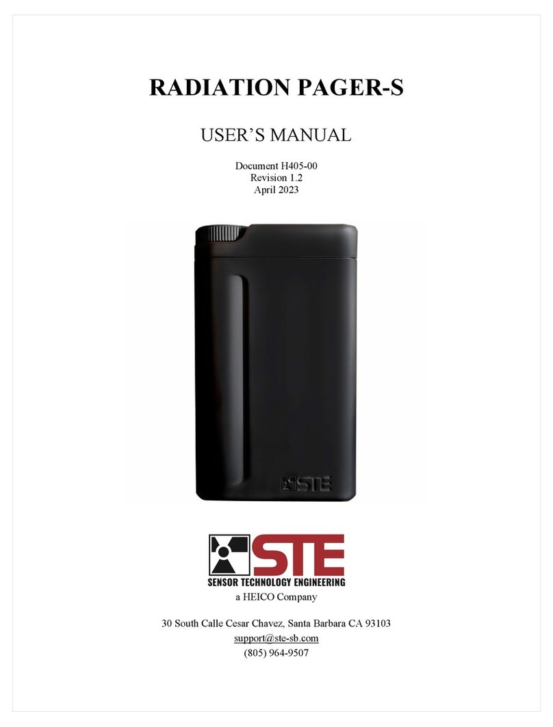
Heico STE RADIATION PAGER-S user manual

Essence Smartcare
Essence Smartcare Care@Home MDsense Getting started
HIK VISION
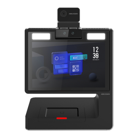
HIK VISION DS-K5032-3XFD quick start guide
Homematic IP
Homematic IP HmIP-SMI55-A Mounting instruction and operating manual
AMC
AMC MOUSE GS Installation
KPS
KPS DETELUX 180IP 110V instruction manual
UE Systems
UE Systems ULTRAPROBE 2000 instruction manual
Field Controls
Field Controls Gas Spillage Sensing Kit GSK-250M instruction manual
Watts
Watts AMES Deringer 40G Installation, operation and maintenance manual
Tecnar
Tecnar accuraspray CS Quick setup guide

Toshiba
Toshiba RBC-AIP1 installation manual
