BrakeBuddy Vantage User manual
INSTALLATION MANUAL
311-0288-053 Rev. A 11/05
FIG. 2
FIG. 1
©2004 Hopkins Manufacturing Corporation Printed in U.S.A
Move seat back.
antage
antage
Phone (800) 470-2287
www.brakebuddy.com
antage
antage
Congratulations on the purchase of your new BrakeBuddy! The
BrakeBuddy was designed and built as an auxiliary braking
system to operate in conjunction with the existing braking
system in your towed vehicle.
Use of the BrakeBuddy in a manner inconsistent with these
instructions may result in damage to your vehicle, serious injury
or death. You must read and understand these instructions
prior to the use of this product.
If you have any questions after reading these instructions, please
call BrakeBuddy customer service at 1-800-470-2287.
1. Remove the BrakeBuddy and components from the shipping
carton. The complete system consists of:
Main BrakeBuddyUnit
Breakaway System
Clevis Assembly
Remote Alert System
2. Install the breakaway system by following the step-by-step
instructions included with the breakaway kit.
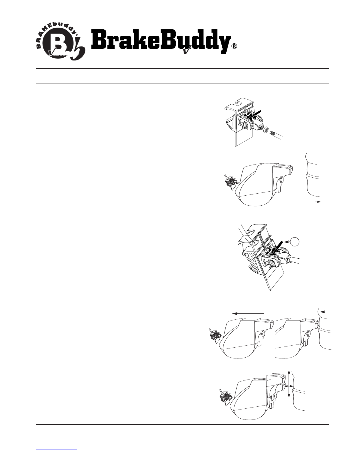
3. Attach the lock nut and clevis assembly to the air cylinder (Fig.1).
4. Adjust the driver’s seat to the far back position (Fig. 2). Place the
BrakeBuddy on the floorboard between the seat and the brake
pedal. Slide the BrakeBuddy back against the seat for maximum
working room.
5. With the notched end of the clevis facing up, attach the clevis to
the top of the towed vehicle’s brake pedal (Fig. 3). Angle the
brake pedal clevis so the upper portion of the clevis grabs the top
of the towed vehicle’s brake pedal. Pull down on the air cylinder
rod (or lower portion of the clevis) to extend the clevis under the
bottom of the towed vehicle’s brake pedal. Pull back on the red
locking tab (A)until secure (tab should not go all the way down).
6. Move the BrakeBuddy forward until the air cylinder rod is fully
retracted (Fig. 4). Make sure the brake pedal is not being
pressed.
7. Adjust the driver’s seat forward until it touches the handle on the
back on the BrakeBuddy (Fig. 5).
8. Adjust the BrakeBuddy handle (Fig. 6). Loosen the adjustment
knob on the back center portion of the BrakeBuddy and adjust the
height of the handle so it contacts the seat at the lowest position
possible without sliding under the seat. (NOTE: the lower on the
seat, the firmer the support). Tighten the adjustment knob to
secure handle.
FIG. 3
A
Move BrakeBuddy forward. Move seat forward.
FIG. 4 FIG. 5
FIG. 6 Adjust handle
up or down to fit
seat at lowest
point.
Lighter
INSTALLATION MANUAL
FIG. 8
FIG. 7
311-0288-053 Rev. A 11/05 © 2004 Hopkins Manufacturing Corporation Printed in U.S.A
Plug into 12-volt
accessory
receptacle.
antage
antage
Phone (800) 470-2287
www.brakebuddy.com
antage
antage
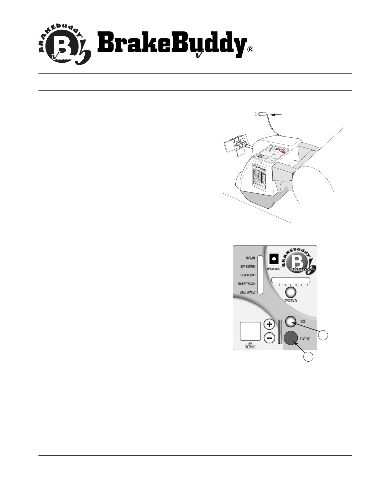
9. Power the BrakeBuddy (Fig. 7). To power the BrakeBuddy,
plug the unit into a 12-volt receptacle in the towed vehicle.
When powered, the air compressor will fill the air tank in 30-40
seconds. If a 12-volt power supply is not available in the
towed position (or the 12-volt power remains off in the ignition
off position), a 12-volt Battery Direct Kit is available (part
number 39305). At a minimum, a 15-amp 12-volt power supply
is required to operate the BrakeBuddy. NOTE: The red
“bleed brakes” light will be lit until completion of step 10.
10. Push the red AUTO START button located on top of the
BrakeBuddy (Fig. 8). The arm will automatically extend / cycle
5times. This will remove any vacuum stored in the brake
vacuum reservoir of the towed vehicle as well as diagnose
any errors in the system startup (B).
NOTE: While the arm is activating, look at the brake lights
on the rear of the towed vehicle. The brake lights will
fluctuate on and off as the BrakeBuddy is pressing on
and off the brake pedal. If the brake lights remain on, the
BrakeBuddy unit is too close to the brake pedal.
NOTE: After Auto Startcycle is complete, the red “bleed
brakes” light will go out and the green “normal” light will
be on.
NOTE: The test button (Fig. 8 / C)is a manual (one time)
arm activation test. The test button can be used to
confirm the unit is in the correct floor position.
WARNING:
Any time the towed vehicle’sengine has been started
(e.g., running through gears, charging battery, etc.)
You Must
push the Auto Start after shutting the towed vehicle’s engine
off. This removes the vacuum out of the vehicle’s brake system.
Failure to drain the towed vehicle’s brake vacuum will result in
excessive tire wear.
11. Make final seat adjustments. If there is a gap between the
seat and handle, adjust the seat forward to close the gap.
B
C
OPERATION INSTRUCTIONS
FIG. 9
VEHICLE WEIGHT FORMULA
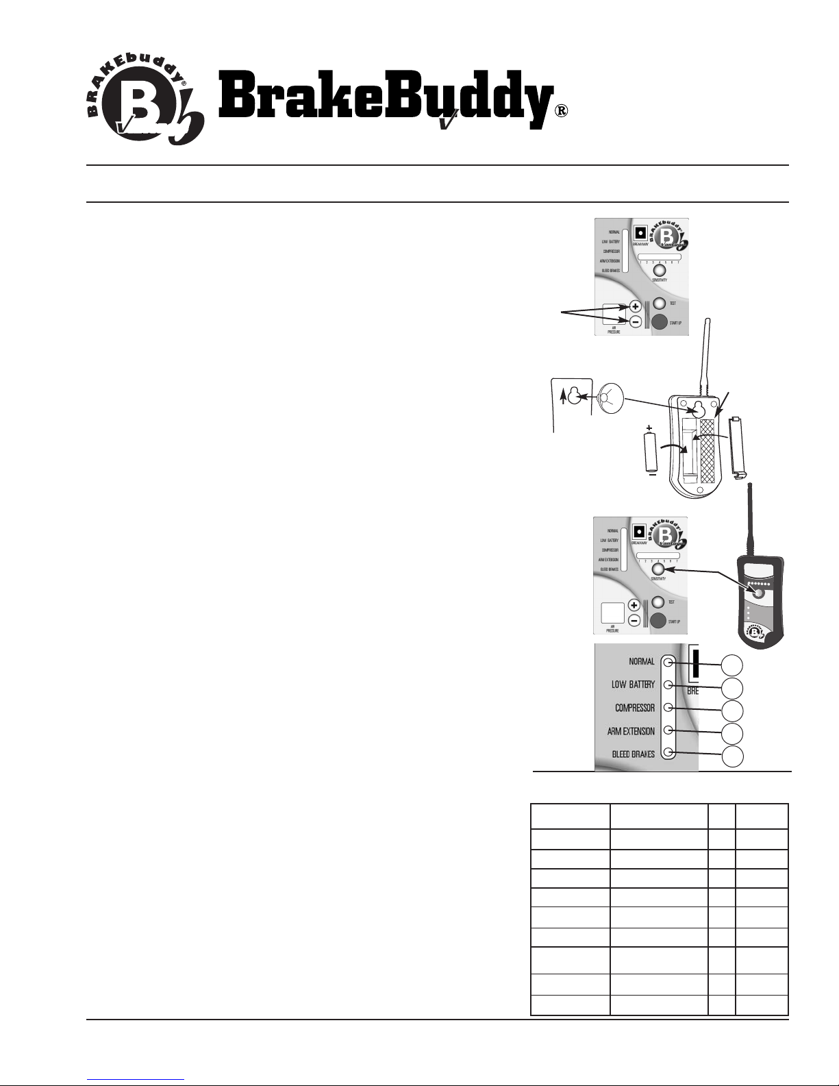
1,500 – 2,000 680 – 907 25 35
2,000 – 2,500 907 –1,134 35 45
2,500 – 3,000 1,134 – 1,361 40 50
3,000 – 3,500 1,361 – 1,588 45 55
3,500 – 4,000 1,588 – 1,814 50 60
4,000 – 4,500 1,814 – 2,041 55 65
4,000 – 4,500 1,814 – 2,041 55 65
1999+ Jeep Gr. Cherokee
4,500 – 5,000 2,041 – 2,268 65 75
5,000 + 2,268 + 75 85
Pounds Kilograms Psi. With Tow
Dolly
311-0288-053 Rev.A 11/05 ©2004 Hopkins Manufacturing Corporation Printed in U.S.A
antage
antage
Phone (800) 470-2287
www.brakebuddy.com
antage
antage
1. Adjust the air pressure to match the weight of your towed
vehicle. The braking pressure, or how hard your towed vehicle
will brake in tow, is adjusted by the +/-Buttons located on top
of the BrakeBuddy (Fig. 9). To find the correct pressure setting
specific for your towed vehicle, please refer to the Vehicle
Weight Formula Chart below. The display will adjust in
increments or decrements of 1 when held down and displays air
pressure from 20 to 90 PSI. After 5 minutes the display will
“power down.” Upon a button press, the display will “power on.”
NOTE:
The DIGITAL DISPLAY shows how much pressure is set to
apply the brake; it does not display the air pressure inside the air
tank that is automatically filled when the BrakeBuddy is plugged
into the 12-volt receptacle.
2. Install the AA battery (included) to the wireless alert system (Fig.
10) and mount in a suitable location in the RV (a suction cup or
hook and loop closure is included for mounting). Adjust the
Sensitivity Button either on the remote or on top of the
main BrakeBuddy unit. The sensitivity button determines how
hard you must apply the brakes in the RVbefore the
BrakeBuddy will engage the brakes in your towed vehicle. The
sensitivity of the BrakeBuddy is adjusted by each push of the
Sensitivity Button (Fig. 11). The more lights are illuminated, the
easier the BrakeBuddy will activate. Each time the BrakeBuddy
is installed, the sensitivity setting remains in the last used setting.
Start at setting #4 and adjust to your preferred setting as you are
driving (using the remote).
NOTE:
Your RV must be moving faster than 15 mph for the
BrakeBuddy to engage the brakes in the towed vehicle.
DIAGNOSTIC FEATURES:
The BrakeBuddy Main Unit provides visual indication on problems
that are occurring (Fig. 12).
A - System Normal (present on main unit)
B-Battery Low (battery voltage has dropped below 10 volts)
Recharge towed vehicle battery before traveling.
C-Compressor Error (air tank is not holding pressure or
compressor is running longer than 3 minutes) Call technical
service immediately 1-800-470-2287.
D - Arm Extension Error (arm is not retracted) Call technical
service immediately 1-800-470-2287.
E-Bleed Brakes (depress the Auto Start button)
FIG. 10
FIG. 11
1234
BRAKING
OCCURING
SENSITIVITY
CHECK BB UNIT
BREAKAWAY EMERGENCY
REPLACEBATTERYON REMOTE
567
Vantage
FIG. 12 A
B
C
D
E
Suction Cup
Installation
Hook and
Loop Position
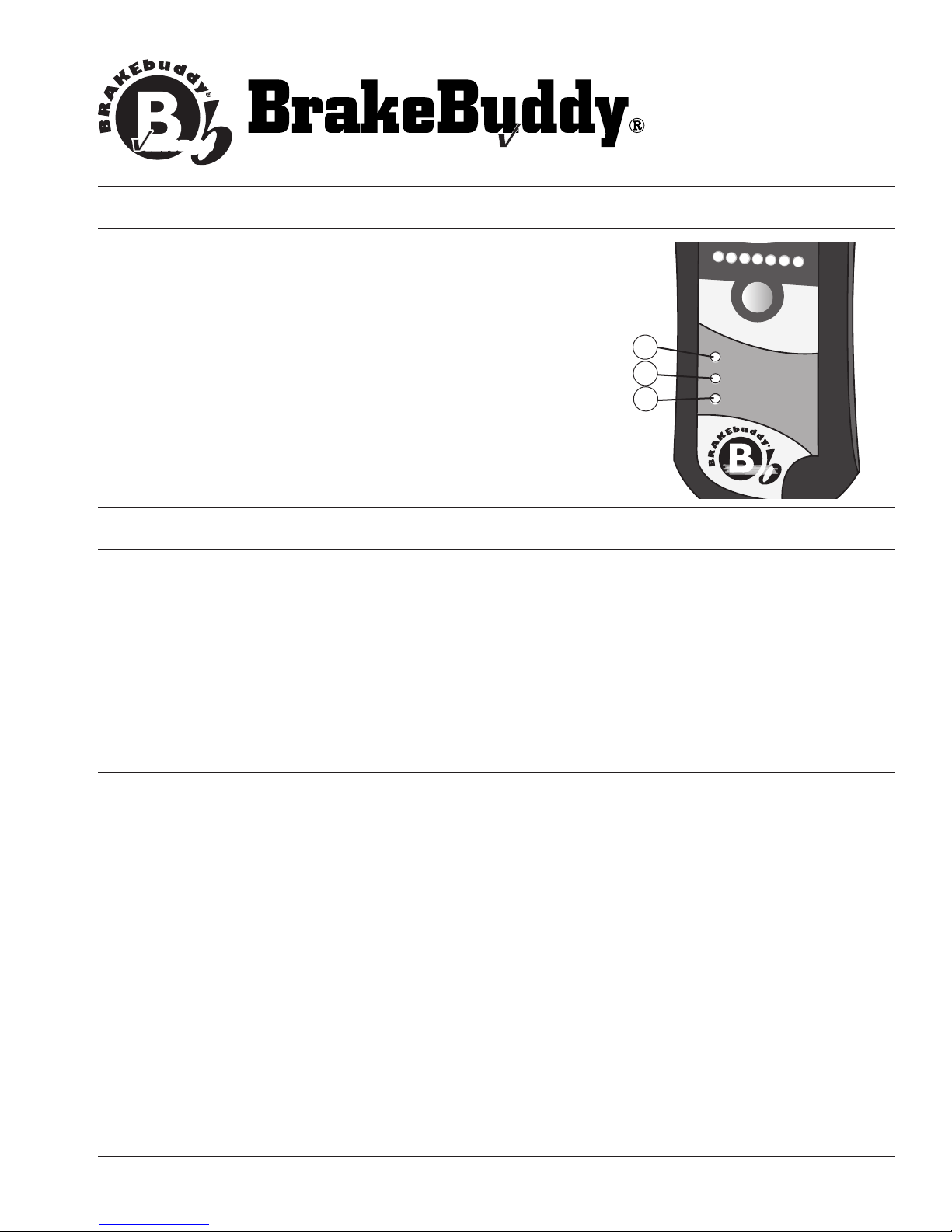
The BrakeBuddy Wireless Remote provides 2-Way
communication from the RV to the towed vehicle and provides
visual indication on problems that are occurring (Fig. 13).
F - Main Unit Error (red light will activate) Stop and check the
main unit diagnostics for error.
G- Breakaway Warning (red light and audible signal will
activate) Stop Immediately!
H- Battery Low on Remote (replace with new AA battery)
OPERATION INSTRUCTIONS
311-0288-053 Rev. A 11/05 © 2004 Hopkins Manufacturing Corporation Printed in U.S.A
antage
antage
Phone (800) 470-2287
www.brakebuddy.com
antage
antage
REMOVAL INSTRUCTIONS
Information to User:
NOTE: This equipment has been tested and found to comply with the limits for a Class B digital device, pursuant
to part 15 of the FCC Rules. These limits are designed to provide reasonable protection against harmful
interference in a residential installation. This equipment generates, uses and can radiate radio frequency energy
and, if not installed and used in accordance with the instructions, may cause harmful interference to radio
communications. However,there is no guarantee that interference will not occur in a particular installation. If this
equipment does cause harmful interference to radio or television reception, which can be determined by turning
the equipment off and on, the user is encouraged to try to correct the interference by one or more of the following
measures:
-Reorient or relocate the receiving antenna.
- Increase the separation between the equipment and receiver.
- Connect the equipment into an outlet on a circuit different from that to which the receiver is
connected.
- Consult the dealer or an experienced radio / TV technician for help.
CAUTION: Changes or modifications not expressly approved by Hopkins Manufacturing Corporation could void
the user’sauthority to operate the equipment.
1234
BRAKING
OCCURING
SENSITIVITY
CHECK BB UNIT
BREAKAWAY EMERGENCY
REPLACEBATTERY ON REMOTE
567
Vantage
FIG. 13
F
G
H
1. To remove the BrakeBuddy from your towed vehicle, unplug the 12-volt adapter from the towed vehicle (the air
pressure in the system will automatically drain).
2. Unplug the breakaway junction box harness from the top of the BrakeBuddy and coil the wire under the
dashboard or floor mat.
3. Adjust the seat back and remove the clevis after the air pressure has drained.
4. Disconnect (unclip) the breakaway safety coil from the breakaway junction box.

Problem: The air compressor will not come on after I plug in the BrakeBuddy.
Solution: Make sure there is power to the 12-volt receptacle and the fuse for the
12-volt plug is functioning. If both are functioning, the red indicator light on
the 12-volt plug will be lit when it is plugged in. To remove the fuse on the
BrakeBuddy’s power cord, unscrew the finger nut on the end of the plug.
Replace fuse with a 15 amp fuse.
Problem: The BrakeBuddy will not apply the brakes in the towed vehicle.
Solution: Make sure the air pressure is properly adjusted for the weight of the towed
vehicle. Also check the sensitivity setting. Remember, your RV must be
moving at least 15 mph for the BrakeBuddy to activate.
Problem: The BrakeBuddy applies the brakes too hard in my towed vehicle.
Solution: Push the AUTO START button before towing to relieve the vacuum in the
towed vehicle’sbrake booster.Or reduce the air pressure by manually
depressing the ( - ) button.
Problem: The BrakeBuddy applies the brake as soon as I plug it in.
Solution: Check that the break-away system is properly connected and the pin is
plugged into the junction box.
Problem: The compressor pumps up and then keeps on pumping slowly.
Solution: There may not be enough current to the BrakeBuddy. You may have a weak
battery or you may need a “12-volt Battery Direct Kit” (part number 39305).
At a minimum, a 15-amp 12-volt cigarette lighter or auxiliary power plug is
required to operate the BrakeBuddy.
Problem: I have to apply the brakes in my motorhome very hard for the Brake
Buddy to come on.
Solution: Increase the sensitivity of the BrakeBuddy by pressing the sensitivity button.
Problem: The BrakeBuddy turns my brake lights on even though I am not
applying the brakes in my motorhome.
Solution: The BrakeBuddy may be too close to the brake pedal thereby activating the
brake lights. See steps 10 & 11of the installation instructions.
Problem: The compressor will not start.
Solution: BrakeBuddy is designed with an automatic shut-off on the compressor when
voltage drops to 9.5 volts.
TROUBLESHOOTING
311-0288-053 Rev.A 11/05 ©2004 Hopkins Manufacturing Corporation Printed in U.S.A
antage
antage
Phone (800) 470-2287
www.brakebuddy.com
antage
antage

Hopkins Manufacturing Corporation thanks you for purchasing BrakeBuddy. A 3-year limited
warranty and a 30-day money back guarantee apply to your BrakeBuddy and BrakeBuddy
accessories. An additional 2-year extended warranty is also available (part number 39307).
We wish you safe and happy travels.
WHAT IS COVERED AND FOR HOW LONG?
We are confident our product will perform well and therefore warrant to you, as the original
retail purchaser, for a period of three years from the date of original purchase, that your new
product will be free of mechanical and electrical defects in material and workmanship.
WHAT WILL BRAKEBUDDY DO? HOW DO I GET SERVICE?
During the warranty period, we will repair or replace your new product (at our option) without
cost to you, which will be your exclusive remedy under this warranty. Please do not return
this product to the place of purchase. Doing so may delay the processing of your
claim and our repair of your product. Call BrakeBuddy Technical Service for return
instructions 1-800-470-2287.
WHAT IS NOT COVERED?
Our warranty for your product will not cover damage resulting from neglect or misuse of the
product, use of improper voltage or current, use contrary to operating instructions, or
disassembly,repair,or alteration by any person other than an authorized service station.
Any implied warranty of merchantability or fitness for a particular purpose of your product is
limited to the duration of this written warranty. We shall not be liable for any incidental or
consequential damages for breach of any expressed or implied warranty on your product.
HOW YOUR STATE'S LAWS MAY APPLY:
Some states do not allow limitations on how long an implied warranty lasts or the exclusion
or limitation of incidental or consequential damages, so the above limitation may not apply
to you. This warranty gives you specific legal rights, and you may also have other rights,
which vary from state to state.
LIMITED THREE-YEAR WARRANTY
311-0288-053 Rev.A 11/05 ©2004 Hopkins Manufacturing Corporation Printed in U.S.A
antage
antage
Phone (800) 470-2287
www.brakebuddy.com
antage
antage
Table of contents
Other BrakeBuddy Automobile Accessories manuals

Popular Automobile Accessories manuals by other brands


ULTIMATE SPEED
ULTIMATE SPEED 279746 Assembly and Safety Advice

SSV Works
SSV Works DF-F65 manual

ULTIMATE SPEED
ULTIMATE SPEED CARBON Assembly and Safety Advice

Witter
Witter F174 Fitting instructions

WeatherTech
WeatherTech No-Drill installation instructions

TAUBENREUTHER
TAUBENREUTHER 1-336050 Installation instruction