Brano Z 100 Installation guide

BRANO a.s, 747 41 Hradec nad Moravicí
the Czech Repub ic
tel.:+420/ 553 632 316, 553 632 303
fax:+420/ 553 632 407, 553 632 151
http://www.brano.eu [email protected]
INSTRUCTION MANUAL
SAFETY PRINCIPLES, OPERATION, MAINTENANCE
F R
CHAIN BLOCKS
type Z 100
- ifting capacity 0,25t 0,5t, 1,6t, 7,5t , 10t ,15t and 20t
type Z 100-1 - ifting capacity 1t a 3,2t
type Z 100-2 - ifting capacity 5t
Read carefully this manual before using the chain block. It contains important safety,
operation, installation and maintenance instructions. Make this manual available to all
responsible persons.
Keep for futher use !
Edition 4.
MARCH 2011
Evidence number 1-52108-0-1

2
CONTENT
1 DEFINITION ..........................................................................................................................................3
2 DEVICE PURPOSE................................................................................................................................3
3 SAFETY PRINCIPLES ..........................................................................................................................4
3.1 SAFETY SUMMARY.....................................................................................................................4
3.2. SAFETY PRINCIPLES ..................................................................................................................4
3.2.1 Prior to us ....................................................................................................................................4
3.2.2 Wh n in us ...................................................................................................................................4
3.2.4 Risk analysis .................................................................................................................................5
3.2.5 Maint nanc ..................................................................................................................................5
4 PACKING, STORAGE AND MANIPULATION..................................................................................6
4.1 PACKING........................................................................................................................................6
4.2 STORAGE .......................................................................................................................................6
4.3 MANIPULATION...........................................................................................................................6
5
MAIN TECHNICAL PARAMETERS ...................................................................................................7
5.1 MECHANICAL CLASSIFICATION..............................................................................................9
5.2 MATERIAL AND DESIGN..........................................................................................................11
5.3 DATA ON PRODUCT ..................................................................................................................10
6 INSTALLATION OF THE CHAIN BLOCK.......................................................................................11
6.1 CHECKING BEFORE THE INSTALLATION............................................................................11
6.1.1 Load carrying structur ...............................................................................................................11
6.2 SUSPENDING OF THE CHAIN BLOCK....................................................................................11
6.2.1 Lubrication of chain....................................................................................................................11
6.2.2 Ch cking th chain position........................................................................................................11
6.2.3 SETTING OF THE HAND CHAIN...........................................................................................12
6.3 CHECKING PRIOR TO USE .......................................................................................................12
7 OPERATION ........................................................................................................................................12
7.1 USE OF THE CHAIN BLOCK.....................................................................................................12
7.2 LIFTING, LOWERING.................................................................................................................13
7.2 SAFETY WORKING ENVIRONMENT......................................................................................14
8 INSPECTION OF THE CHAIN BLOCK.............................................................................................14
8.1 INSPECTION ................................................................................................................................14
8.1.1 Insp ction classification..............................................................................................................14
8.1.2 Daily insp ction ..........................................................................................................................14
8.1.3 R gular insp ction.......................................................................................................................15
8.1.4 Chain block occasionally us d....................................................................................................15
8.1.5 Insp ction r cord.........................................................................................................................15
8.2 INSPECTION PROCEDURE........................................................................................................15
9 FAULTS FINDING ..............................................................................................................................19
10 LUBRICATION..................................................................................................................................19
10.1 GENERALLY..............................................................................................................................19
10.2 GEARINGS .................................................................................................................................19
10.3 LOAD CHAIN.............................................................................................................................19
11 MAINTENANCE................................................................................................................................20
11.1 SAFETY PRINCIPLES ...............................................................................................................20
11.2 REPLACEMENT OF THE LOAD CHAIN................................................................................20
11.2.1 SINGLE FALL CHAIN............................................................................................................20
11.2.2 MULTI FALL CHAIN .............................................................................................................21
11. 3 BRAKE ADJUSTMENT............................................................................................................21
11.4 GENERAL INSTRUCTIONS .....................................................................................................21
11.5 CHECK........................................................................................................................................22
11.6 REPAIR .......................................................................................................................................22
11.7 TEST............................................................................................................................................22
12 REMOVING FROM OPERATION – LIQUIDATION .....................................................................22
13 RELATED DOCUMENTATION.......................................................................................................22
14 FINAL REQUIREMENTS OF THE MANUFACTURER TO THE CUSTOMER...........................23

3
1 DEFINITION
! DANGER
Danger: is used to indicate the presence of hazard, which will cause
death or severe injury, if the warning is ignored.
! WARNING
Warning: is used to indicate a possible hazard, which could cause
death or severe injury, if the warning is ignored.
! CAUTION
Caution: is used to indicate a possible hazard, which could
cause light injury, if the warning is ignored. Caution can warn
against dangerous practices as well.
Lifting capacity (Q): indicates the maximum permitted mass of a load (working load
limit), which a chain block is designed to support in general service under conditions
defined in this manual.
2 DEVICE PURPOSE
2.1 The chain block
type Z 100, lifting capacity 0,5t, 1,6t, 7, 5t,10t, 15t and 20t
type Z 100-1, lifting capacity 1t and 3,2t
type Z 100-2, lifting capacity 5t
has been designed solely for hand vertical lifting and lowering of free loads in the
workplace. The load mass must not exceed the specified nominal lifting capacity.
2.2 The chain block has been designed to meet requirements provided by Directive
2006/42/EC of the European Parliament and of the Council as amended by the Czech
technical regulation – ministerial order No. 176/2008 of the Coll. of Laws as amended
as well as requirements of the ČSN EN IS 12100-1, ČSN EN IS 12100-2, ČSN EN
IS 14121-1 and ČSN EN 13157 harmonized technical standards.
2.3 The chain block has been designed to meet requirements for the group I of
devices (mine) category M2 according to the Directive 94/9/EC of the European
Parliament and of the Council as amended by the Czech technical regulation –
ministerial order No. 23/2003 of the Coll. of Laws as amended as well as
requirements of the ČSN EN 13463-1 harmonized Czech technical standard and
fulfils the conditions for use in the „dangerous atmospheric conditions 2“ environment
according to the ČSN EN 1127-2 standard with the limitation according to the national
regulation – CBM (Czech Bureau of Mine) regulation No.22/89 of Coll. of Laws § 232
section (1) c) up to 1,5% of mine gas accumulation.
2.4. The chain block has been designed to meet requirements specified for the group
II of devices (non-mine) category 2 and 3 according to the Directive 94/9/EC of the
European Parliament and of the Council as amended by the Czech technical
regulation – ministerial order No. 23/2003 of the Coll. of Laws as amended as well as
requirements of the ČSN EN 13463-1 harmonized Czech technical standard and
fulfils the conditions for use in the „zone 1 and zone 21“, „zone 2 and zone 22“
environments according to the ČSN EN 1127-1 standard.
Note: 2.3 and 2.4 articles apply for the chain block designed for use in environment
with explosion hazard.

4
3 SAFETY PRINCIPLES
3.1 SAFETY SUMMARY
Danger exists when loads are lifted, particularly when the chain block is not used
properly or is poorly maintained. Because an accident or serious injury could result,
special safety precautions apply to the operation with the chain block during its
assembly, maintenance and inspection.
! WARNING
NEVER use chain block for lifting and transporting people.
NEVER lift or transport loads over or near people.
NEVER lift more than lifting capacity shown on the chain block nameplate.
ALWAYS make sure the load carrying structure will provide adequate support to
handle fully loaded chain block and all the lifting operation.
ALWAYS let people around to know when a lift is about to begin.
ALWAYS read the operation and safety instructions.
Remember proper
rigging and lifting techniques are the responsibility of the operator.
Check all applicable national directions, regulations and standards for further
information about the safety use of your chain block.
3.2. SAFETY PRINCIPLES
! WARNING
3.2.1 Prior to use
ALWAYS ensure physically fit, qualified and instructed persons over 18 years of
age, familiarized with this manual and trained in safety conditions and way of
work, operate the chain block.
ALWAYS check the chain block daily before use according to the section 8.2.(1)
„Daily inspection“.
ALWAYS make sure the length of chain is long enough for the intended job.
ALWAYS check the brake function before use.
ALWAYS use original chain only.
ALWAYS ensure the load chain is not corroded, is cleaned and oiled.
ALWAYS make sure the last link of load chain is strongly fastened to the body.
NEVER use damaged or worn out chain block.
NEVER use chain block with jumped out, damaged or missing hook’s safety latch.
NEVER use a chain block without a visible marking of the lifting capacity.
NEVER use modified or deformed hooks.
NEVER connect or lengthen the load chain.
NEVER use a chain block marked by the label „OUT OF SERVICE“.
ALWAYS consult the manufacturer or his authorized representative, if you plan to
use a chain block in non-standard or extreme environments.
3.2.2 When in use
ALWAYS make sure the load is properly seated in the hook.

5
ALWAYS make sure the safety latches of hooks work in the correct way.
ALWAYS pay attention to the limit positions.
ALWAYS use manual power only.
ALWAYS when lifting loads approaching the nominal lifting capacity we
recommend, regarding the operating forces, the operation was ensured
by two persons.
NEVER use a chain block for tensioning, pulling or anchoring loads.
NEVER allow swinging the load, causing impacts or vibrations.
NEVER use a chain as a sling.
NEVER hitch a load on the tip of the hook.
NEVER pull the chain over any edge.
NEVER weld, cut or make any operation on a suspended load.
NEVER use a chain as a welding electrode.
NEVER operate a chain block, if chain is jumping or atypical or
excessive noise occurs.
3.2.3 After use
NEVER leave a load suspended.
ALWAYS ensure the chain block against incompetent use.
3.2.4 Risk ana ysis
The analysis of possible risks in light of design, operation and environment of the
chain block application is presented in freestanding document „Risk analysis“. This
document can be required in service centers.
3.2.5 Maintenance
ALWAYS enable qualified personnel inspect the chain block regularly.
ALWAYS ensure the chain was clean and oiled.
ALWAYS ensure the sliding parts were greased enough.
NEVER add other parts for lengthening the load chain.
nly such interventions can be done when maintaining that are in compliance with
requirements of the manufacturer specified in the chapters 11 and 14 of this manual.
IT IS NOT PERMISSIBLE to carry out repairs and maintenance in other way than
prescribed by the manufacturer. It concerns namely the forbiddance of using of
unoriginal spare parts or carrying out modifications on the product without an approval
of the manufacturer.

6
4 PACKING, STORAGE AND MANIPULATION
4.1 PACKING
Chain blocks by the lifting capacity 5t are supplied assembled and packed in carton
boxes. Chain blocks of lifting capacity 7,5t,10t, 15t and 20t are supplied free loaded on
pallets packed in foil.
4.1.2 The following accompanying documentation is a part of the delivery:
a) Instruction Manual
b) EC Declaration of Conformity
c) Certificates of Quality and Completeness and Guarantee Card.
c1) Guarantee period is stated in the Guarantee Card.
c2) The guarantee does not apply to defects caused by infringement of the
instructions stated in this Instruction Manual and defects occurred owing
to improper use and unskilled intervention.
c3) The guarantee does not apply also to modifications on the product or
using of unoriginal spare parts without an approval of the manufacturer.
c4) Claim of product defects is carried out according to applicable provisions
of commercial code eventually as amended.
d) List of service centers (for the Czech and Slovak Republics only).
4.2 STORAGE
Store chain blocks in dry and clean stocks free from chemical influences and vapours.
(1) Always store chain blocks without any suspended load.
(2) Remove all dust, water and impurity from the chain block.
(3) Lubricate chain, pivot of roller, pivots of hook and springs of hooks safety latches.
(4) Suspend the chain block in a dry place.
(5) During the further use follow instructions of the section 8.1.2 „Daily inspection” or
8.1.4 „Chain block occasionally used“.
4.3 MANIPULATION
During transportation and manipulation follow the applicable technical regulations and
standards for work with heavy loads.

7
5 MAIN TECHNICAL PARAMETERS
Lifting capacity 0,25 – 10 t
TABLE 5.
A
Type
Lifting
capacity
(t)
Number of
chain falls
Chain
ČSN
EN 818-7
(
strength
class 8)
perating
force
(N)
Lifting
1)
speed
(m/min)
Working
temperatu
re range
Basic
2)
lift
(m)
Weight
(kg)
Z100 0,25 1
∅3,1x9,3
270 2 4,4
Z100 0,5 1
∅5x15
300 1,1 8,5
Z100-1 1 1
∅7x21
350 0,7 14,1
Z100 1,6 1
∅9x27
320 0,36 24
Z100-1 3,2 1
∅11x31
400 0,29 37,4
Z100-2 5 2
∅11x31
400 0,15 52,3
Z100 7,5 2
∅11x31
480 0,15 70
Z100 10 3
∅11x31
400 0,1
-20°C
to
+50°C
3
85
Not s:
1) Calculat d on pr sumption of winding off 30m of th hand chain p r minut .
2) Maximum standard lift is 15m. R quir d lift is n c ssary to b sp cifi d in th ord r.
Lifts xc ding 15 m must b consult d with th manufactur r.
TABLE 5.
B
-
DIMENSIONS
Main dimensions – informative (mm) Lifting
capacity
(t) a D L
min
e
min
d
0,25 120 80 255 18,5 30
0,5 165 115 250 18,5 30
1 180 136 330 23,5 36
1,6 220 198 410 29,5 43
3,2 254 220 510 35,5 50
5 254 220 655 39,5 56
7,5 254 220 875 43 56
10 254 220 1000 47 63

8
Lifting capacity 15 and 20 t
TABLE 5.c - Technica parameters
Type
Lifting
capacity
(t)
Number of
chain falls
Chain ČSN
EN 818-7
(strength
class 8)
perating
force on one
chain block
(N)
Lifting
1)
speed
(m/min)
Working
temperat
ure
range
Lift
2)
max.
(m)
Weight
without
chain
(kg)
Increase of
weight for
1m of lift
(kg)
15 4 480 0,15 12 280 13
Z100
20 6
∅11x31
400 0,1
-20°C
to
+50°C
8 350 19,2
Not s:
1) Calculat d on pr sumption of winding off 30m of th hand chain p r minut on ach chain
block.
2) Lift bas d on th ord r. Lifts xc ding tabl valu s must b consult d with th manufactur r.
TABLE 5.
D
- DIMENSIONS
Main dimensions – informative (mm) Lifting
capacity
(t) a b L
min
e
min
D
15 510 980 910 53 71
20 510 1100 950 60 80

Chain blocks of lifting capacity 15 and 20t are standardly equipped with chain
stackers.
5.1 MECHANICAL
CLASSIFICATION
Safety and life of the chain block is guaranteed under presumption it works in
accordance with the specified classification.
Chain block is design for class 1Bm according to the regulation FEM 9.511 – see
table 5.1. (corresponds to classification of the mechanism M3 according to the IS
4301/1).
Average daily working time is set by the load spectrum.
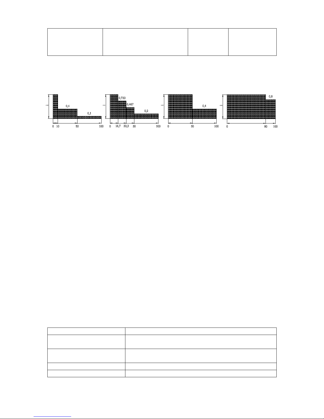
Tab e 5.1 MECHANICAL CLASSIFICATION
Load spectrum
(Load distribution)
Definition Cubic mean
value
Average daily
operating time
(h)
1
(light)
Chain blocks usually subj ct to
small load and in xc ptional
cas s only to maximum load.
k≤0,50
1 - 2
2
(m dium)
Chain blocks usually subj ct to
small load but rath r oft n to
maximum load.
0,50< k ≤ 0,63
0,5 - 1
3
(h avy)
Chain blocks usually subj ct to
m dium load but r p at dly to
maximum load.
0,63< k ≤ 0,80
0,25 – 0,5
b
L
D
e
min.
min.
a
10
4
(v ry h avy)
Chain blocks usually subj ct to
maximum or almost maximum
load.
0,80< k ≤ 1,00
0,12 – 0,25
Load spectrum Load spectrum Load spectrum Load spectrum
1 2 3 4
% operating time
5.2. MATERIAL AND DESIGN
5.2.1 Main parts of the chain block are manufactured from structural steel and cast
iron, braking inserts of brake from brass or ceramic-metallic material.
5.2.2. Materials inclinable to creation of an incendiary spark in terms of the annex No.
2 article 1.3.1 to the ministerial order No. 23/2003 of the Coll. of Laws and the
ČSN EN 1127-2 article 6.4.4 ČSN EN 1127-1 article 6.4.4 and ČSN EN 13 463-
1 article 8.1 harmonized technical standards are not used.
5.2.3 Materials with dangerous effects of static electricity within the meaning of the
ČSN EN 1127-2 article 6.4.7, ČSN EN 1127-1 article 6.4.7, ČSN EN 13463-1
article 7.4.3 and ČSN 33 2030 are not used in the chain block.
5.2.4 The chain block does not exceed the noise values specified in the annex 1
article 1.7.4.2 letter u of the M No. 176/2008 of the Coll. of Laws (EP and RE
directive No. 2006/42/EC)
Note: Articles 5.2.2 and 5.2.3 apply for chain block design to environment with
explosion risk.
5.3 DATA ON PRODUCT
Every product is fitted with label with specified data as follows:
Standard design: Design to environment with exp osion risk:
Manufacturer’s identification
Manufacturer’s identification
Address of the
manufacturer
Address of the manufacturer
Type of product Type of product
Lifting capacity Lifting capacity

11
Serial number Serial number
Year of production Year of production
CE marking CE marking
symbol of protection type(I M2 for group I , II 2G for
group II)
6 INSTALLATION OF THE CHAIN BLOCK
Prior to installation check the chain block for possible damages.
6.1 CHECKING BEFORE THE INSTALLATION
6.1.1 Load carrying structure
! WARNING
ALWAYS make sure the load carrying structure is firm enough to support the
weight of load and chain block. The installation must not be provided onto the
structure, where the carrying capacity cannot be checked.
ALWAYS the user is responsib e for the oad carrying structure!
6.2 SUSPENDING OF THE CHAIN BLOCK
! CAUTION
Be careful during suspending the chain block on the pendant element and ensure
appropriate conditions for safety installation according to the environment character
(working platform, auxiliary lifting device, etc), to avoid endanger or injury of people.
Use safety equipment when suspending the chain block in heights.
User is responsib e for creating the working conditions for insta ation and
providing the insta ation of the chain b ock.
6.2.1 Lubrication of chain
Put the thin layer of oil on the chain, preferably by means of spray. Regular
lubrication will avoid wear and corrosion of chain and lengthen its life.
6.2.2 Checking the chain position
Check, whether the hook is not kinked or twisted as on the picture 1 and 2. If the
chain is twisted, put it to its correct position. Never suspend a load on the twisted
chain. Chain is not twisted, when the welded parts of all the links are in one row. It is
applicable for lifting capacity 5t and higher. Pay increased attention to checking of the
chain position at lifting capacity 15 and 20t.
THE CHAIN MUST
BE STRAIGHTEN S
AS THE LUGS
AFTER WELDING
WERE N NE SIDE
NLY
Obr. 1 Twisting of a chain
BY TURNING FF THE
PULLEY THE
TWISTING F THE
CHAIN APPEAR.
BY ITS TAKING BACK,
THE CHAIN GET
STRAIGHTEN AGAIN.
Obr. 2 Kinking of a chain

12
Lift
6.2.3 SETTING OF THE HAND CHAIN
After the installation of the chain block in the workplace we
check the position of the hand chain. The distance of the
end of bottom loop of the hand chain over the level of the
surface, on which operation staff of the chain block stands
during the operation, must be in the range 500 –1000mm.
Chain blocks are supplied with a hand chain, the length of
which is proportional to the lift of the chain block and during
the installation meets condition of correct setting of the chain
end.
In other cases, where regarding a way of use of the chain
block, the length of the hand chain does not meet prescribed
conditions, the chain must be shortened or lengthened.
Shortening of the chain: we disconnect the chain in place of
the coupling link by buckling free ends of the links. We
shorten the chain by required length and connect again by
coupling link. Free ends of the coupling link we bend to one
another.
Lenghtening: we disconnect the chain in place of the
coupling link by buckling free ends of the links. We attach
other part of chain of required ength by means of two
coupling links. Free ends of coupling links we bend to one
another.
Coupling links and hand chain of required length can be
bought as spare parts.
Note: the request for operating chain of other length than
standard one can be made just in the order.
6.3 CHECKING PRIOR TO USE
! CAUTION
(1) First look again through the previous articles of this manual and make sure all
steps were correctly done and all parts are safely assembled.
(2) check, whether hooks are correctly suspended and safety latches snapped in.
(3) Check visually load carrying structure or pendant elements, whether they are
without defects.
(4) By several motions of the hand chain check the function of the chain block without
a load.
(5) Provide several lifting and lowering with a suitable load (10% to 50% lifting
capacity). At the same time check the brake, whether it helds the load without
slipping during its lowering and stopping.
7 OPERATION
7.1 USE OF THE CHAIN BLOCK
The chain block is multipurpose device intended for lifting and lowering of loads
under normal condition in workplace and in environments with the explosion hazard
13
as well, if a protection type symbol is marked on the label – see articles 2.3, 2.4 and
5.3 of this manual. It is operated by means of the hand chain. It is designated for
organizations and private persons.
Since dealing with heavy loads may involve unexpected danger, all “Safety
instructions” according to the chapter 3 must be kept.
! WARNING
The last link of the load chain is anchored to the body of the chain block. The
anchoring just prevent sliding off the load chain and is not determined for holding the
load.
Do not continue in operation with if the tensioning of the anchored end of the load
chain occurs. Damage of the chain anchoring can cause fall of the load..
7.2 LIFTING, LOWERING
Lifting and lowering is provided by pulling on the hand chain of the chain block. Lifting
or lowering can be interrupted at any height of the lift.
! WARNING
At chain block with a great lift (15 and more meters) a dangerous heating up of the
brake can take place when lowering loads in exceptional cases (uninterrupted and
quick lowering). In such cases it is necessary to lower loads slowly and intermittently.
! CAUTION
When lifting loads being in a lifted state hanged over to other lifting device
(crane, forklift truck etc.) it is necessary to relieve the load chain (chains) of the chain
block only by means of the hand chain of the chain block not by lifting loads by
means of the other lifting device. nly the mentioned procedure guaranties a
trouble-free releasing brake of the chain block after removal of the load.
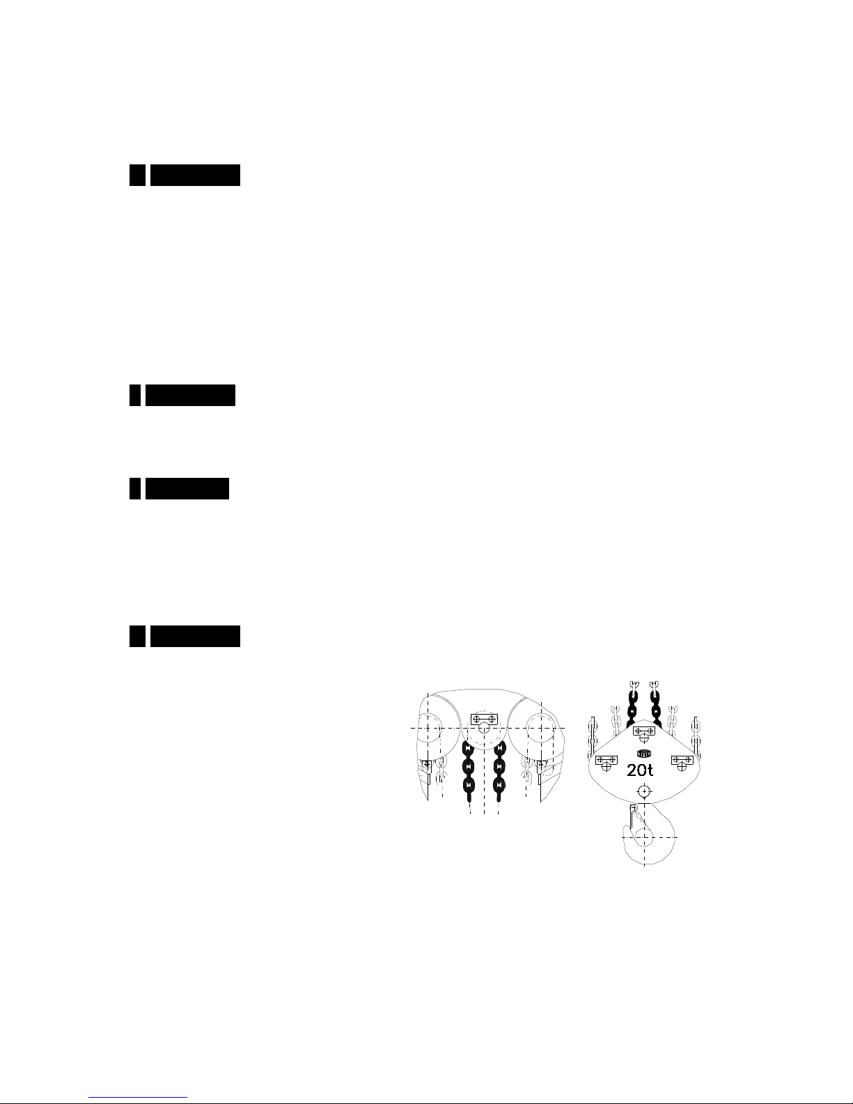
! WARNING
Cain blocks of lifting capacity
15t and 20t are intended in
principle for operational staff
consisting of several members
(at least of two ones). The
speed of winding off the chain
when lifting or lowering must be
balanced on both chain blocks
– synchronized so that in both
stackers was the same length
of the chain. The operating staff
must check a balancing of the
coulor coded central parts of
the chain on the upper sheave
(Z100/15t) or block pulley
(Z100/20t).

14
7.3 SAFETY WORKING ENVIRONMENT
! WARNING
(1) perator must be demonstrably familiarized with this instruction manual,
follow applicable safety and hygienic regulations and be qualified to this equipment
service.
(2) In the course of work with the chain block the operating staff must be equipped
with helmet, gloves and suitable footwear.
(3) nly verified binding means of appropriate lifting capacity is to be used for binding
loads.
(4) When more persons take part in the operation always one person responsible
for manipulation with the chain block and trained in work safety must be
determined.
(5) The operator must have a clear and unobstructed view of the working area before
staring the work. If it is not possible, a second or more persons must help to
supervise in the nearby area.
(6) The operator must check, the entire workplace is safe and whether there is a
possibility of escaping in case of endanger, before operating the chain block.
(7) During work with the chain block, the sufficient distance of the operator from the
load must be kept. It is prohibited to lift or lower bulky loads preventing to keep
sufficient distance.
(8) When operating the chain block in limited areas you must prevent the hook or
loads does not hit into obstacle or to chain block body.
8 INSPECTION OF THE CHAIN BLOCK
8.1 INSPECTION
8.1.1 Inspection c assification
(1) Initial inspection: prior to initial use. All new or repaired chain blocks shall be
inspected by a designated qualified person to ensure compliance with the applicable
provisions of this manual.
(2) Inspection procedures for chain blocks in regular service are divided into two
general classifications based on the intervals at which should be performed. The
intervals are dependent upon the nature of the critical components of the chain block
and the degree of their exposure to wear deterioration or malfunction. The two
general classifications are herein designated as daily and regular. The respective
intervals are defined in the following way:
(a) Dai y inspection: visual examination provided by the operating personnel or
person designated by the user at the beginning of each usage.
(b) Regu ar inspection: visual inspection provided by the qualified person
designated by the user.
1) normal operation – annually,
2) heavy operation – twice per year,
3) special or infrequent operation – as recommended by a qualified person
designated by the user prior to first use and according to the directions of the
qualified operating personnel.
8.1.2 Dai y inspection
Inspect for damages and defects items such as those listed in section 8.2(1) “Daily
inspection. Provide this inspection also during operation in the interval between

15
regular inspections. A qualified personnel shall determine, whether any defects or
damages constitute a hazard or will require more detailed inspection.
8.1.3 Regu ar inspection
Complete inspections of the chain block shall be performed as recommended regular
inspection. These inspections may be performed with the chain block in its normal
location and do not require dismantling the chain block. The recommended regular
inspection defined in the section 8.2(2) must be performed by qualified persons
determining whether the complete disassembly is necessary. These inspections
include also the requirements of daily inspections.
8.1.4 Chain b ock occasiona y used
(1) A chain block that has been idle for a period of one month or more but less than
one year shall be given an inspection conforming to the requirements of the section
8.1.2 before it is placed again in operation.
(2) A chain block that has been idle for a period of one year shall be given an
inspection conforming to the requirements of section 8.1.3 before it is placed in
operation.
8.1.5 Inspection record
Keep always the record of the performed tests, repairs, inspections and maintenance
of chain blocks. Carry out dated inspection records at time intervals specified in the
section 8.1.1 (2) (b) and keep them available in the palce designated by the user.
Defects found by the inspection or recorded during the operation must be announced
to the person designated by the user who is responsible for work safety.
8.2 INSPECTION PROCEDURE
(1) Dai y inspection (provided by the operator or competent person)
PART INSPECTI N
METH D
LIMIT/CRITERIA
F R DISCARD
REMEDY
1. Function of chain
block
Visual, list ning Chain binds, jumps,
mak an xc ssiv
nois , tc.
Cl an and lubricat
th chain, if th
troubl is not
r mov d, r plac th
chain.
2. Fastening parts Visual ch ck of all
bolts, nuts, riv ts tc.
D f ctiv or missing
parts
Loos parts
R plac by th n w
on .
Fast n loos d parts
2. Hooks
(1) App aranc
(2) Hook rotating
(3) Saf ty latch of
hook
Visual
Rotat hook around
its axis by manual
springing of saf ty
latch.
Saf ty latch jump d
out from th top of
th hook, bind shank,
oth r visibl hook
d formation.
Hook do s not rotat
flu ntly or scrub.
Saf ty latch do s not
r turn aft r pushing
Prof ssional ov rhaul
of lifting d vic –
xchang of hook and
oth r damag d parts.
Cl an and lubricat .
Cl an, lubricat ,
r pair or xchang .

16
4. Load chain
(1) App aranc
Visually ch ck th
whol chain.
Cracks in th plac of
w lding, cross nocks,
d formation,
xc ssiv w ar,
corrosion
Exchang of th
chain.
Not :
Th compl t w ar of th
chain cannot b d t rmin d
by th visual insp ction.
Wh n w ar sign is found
ch ck th chain according to
“ R gular insp ction”.
(2) Lubrication
(3) S tting in th
chain
(4) Kink d chain
tackl block (only
at two loading
chain strands)
Visual
Visual ch ck
according to pic.1,
wh th r th chain is
not kink d.
Visual according to
pic.2
Chain is not
lubricat d.
Th chain is kink d or
twist d; w lds ar not
in a row.
Chain is kink d du to
kink d tackl block,
w lds ar not in a
row.
Cl an and lubricat
th chain.
Straight n th chain
and s t to normal
position.
Straight n th chain
by turning back th
tackl block
4. Hand chain
Visual Chain is kink d or
twist d.
Chain is d form d or
damag d and do s not
com corr ctly to
chain wh l.
Straight n th chain
and s t to normal
position.
Exchang of th
chain.
(2) Regu ar inspection (provided by a qualified person)
PART INSPECTI N
METH D
LIMIT/CRITERIA
F R DISCARD
REMEDY
1. Fast ning parts.
Visual ch ck of all
bolts, nuts, riv ts,
tc.
D f ct d or missing
parts
Loos parts
R plac by th n w
on .
Fast n loos d parts
2. All parts Visual ch ck. Worn or damag d
parts.
Dirty and not
lubricat d parts.
R plac by th n w
on .
Dismantl , cl an,
lubricat and
ass mbl again.
W ar in this part
W ld d part

17
3. Nam plat –
marking of lifting
capacity on th chain
block
Visual ch ck Ill gibl lifting
capacity.
R pair or r plac by
th n w on .
R pair marking on th
chain block.
4. Hooks
(1) D formation of
hook
(op ning)
(2) Hook w ar
M asur dim nsion
„C“ with slid
callip r.
Visual ch ck.
M asur dim nsion
„A“ and „B“ with a
slid callip r.
M asur d valu is
high r th n sp cifi d
by th tabl .
D formation is visibl
during visual ch ck.
Do not us th hook,
if dim nsions „A“ or
„B“ w r d cr as d
mor th n 10%.
T chnical insp ction
of lifting d vic –
xchang of hooks
and oth r damag d
parts.
Worn or d form d
hook r plac by th
n w on .
5. Chain - prolongation
- colour marking
(appli d for 15 and
20t)
M asuring of th
pitch with th slid
callip r, m asur at
th point that is most
fr qu ntly ngag d
with th sh av and
th nut.
Visual ch ck
Dim nsion „p“ must
not xc d limit
valu s shown in th
following tabl .
Colour is not visibl .
If limit valu s ar
xc d d ask for
r plac m nt of th
chain.
Paint th c ntral part
of th chain with r d
colour in l ngth about
600 mm
Standard Limit Standard Limit
0,25 17,6 15,8 16 14.5
0,5 17,5 15,8 16 14,5
1 22 19,8 19 17
1,6 26 23,4 23 20
3,2 36,5 32,8 34 30,5
5 42 37,8 35 31,5
7,5 48 43,2 38 34,2
10 58 52,2 45 40,5
15 67 63,3 53 47.7
20 75 67,5 60 54
59
66
24
52
47
24
35
41
45
29
Capacity
( t )
Dimension "A" (mm) Dimension "B" (mm) Dimension "C" (mm)
Limit

18
6. Brak
- function
Susp nd th load of
w ight qual to lifting
capacity of th chain
block, lift it at min. 250
mm and low r.
Aft r int rrupting th
op ration, th brak
must k p th load in
any position of lifting
or low ring.
If this do s not
happ n, ask for r pair
and th brak
adjustm nt.
7. Anchoring th
chain.
Visual ch ck. Th nd of th chain
is not fast n nough
to th body.
Fast n th fixing bolt.
R pair damag d joint
or r plac .
8. Pawl - function Visual ch ck during
lifting.
Pawl do s not snap to
t th of ratch t wh l.
Cl an, lubricat or
r plac th spring.
9. Rotating of
block sh av .
Rotat th block sh av
by pulling th chain.
Th block sh av
rotat smoothly.
Cl an, lubricat or
r pair.
Standard Limit
∅3,1
11
102 105
3,2
∅55 75 77,3
4,5
∅75 105 108,2
6,3
∅9 5 135 139,1
8,1
∅11 5 155 159,7
9,9
Size of the
chain (d)
Number of
measured
links
Pitch of measured links
p x 5 (px11)
Discard limit
for (
d )
ppppp

19
9 FAULTS FINDING
Situation Cause Remedy
1. Th chain block do s not
k p th load.
Brak slipping. Brak adjusting or r pair
according to chapt r
„Maint nanc “.
2. Th chain block lifts hard
or fails to lift th load.
(1) Chain block is ov rload d.
(2) Damag d g aring.
(1) D cr as th w ight of
load to th nominal lifting
capacity.
(2) Ch ck th parts according
to th chapt r
„Maint nanc “.
3. Chain has bad approach,
jams.
Damag d or worn chain or
nut.
Ch ck th chain or parts
according to “R gular
insp ction“ or provid r pair
according to th chapt r
„Maint nanc “
4. Abnormal sounds com s
from th chain block.
1) Not nough lubricat d
chain.
2) Not nough lubricat d
g aring.
3) Worn sh av .
1) Lubricat th chain.
2) Lubricat th g aring.
3) R plac th sh av .
5. In audibl charact ristic
sound during falling of th
pawl to claw of ratch t wh l.
Loos of pawl function.
Rust, impuriti s, brok n
spring.
Cl an, r plac th spring.
6. Saf ty latch of hook do s
not work.
(1) Damag d saf ty latch.
(2) D form d hook.
(1) R pair th saf ty latch.
(2) Ch ck th hook – s
„Daily insp ction“.
10 LUBRICATION
10.1 GENERALLY
Before the application of the new lubricant, remove the old one, clean parts by the
solvent and put the new lubricant. Use the lubricant specified by the manufacturer.
10.2 GEARINGS
Dismantle the cover on the opposite side of the chain wheel.
Remove the old lubricant and replace by the new one. Use grease PM – A2 or its
equivalent.
10.3 LOAD CHAIN
! CAUTION
The wrong maintenance and inappropriate lubrication of the chain can be a cause of
a serious accident.

20
NUT
UN LOADED STRAND
OF C AIN
END LINK OF T E OLD
C AIN
LOADED STRAND OF
C AIN
END LINK OF T E NEW
C AIN
C - LINK
Pictur . 11.2 – R plac m nt of th load chain
ALWAYS lubricate the chain 1 x per week or more often according to the intensity
of the service.
ALWAYS lubricate more often in corrosive environment than under normal
circumstances (salt water, sea environment, acids, etc.).
ALWAYS use machinery oil according to IS – VG 46 or VG 48 or their
equivalent.
11 MAINTENANCE
11.1 SAFETY PRINCIPLES
! WARNING
With exception of rep acing the chain and brake adjustment on y qua ified
personne (service organizations) trained in safety and maintenance of these
chain b ocks can carry out maintenance, inspections and tests.
ALWAYS use parts supplied solely by the manufacturer.
It is not permitted to make repairs and maintenance in other way than prescribed by
the manufacturer. It concerns especially the forbiddance of using of unoriginal spare
parts or performing of modifications on the product without an approval of the
manufacturer.
ALWAYS check the function of the chain block after providing maintenance.
ALWAYS mark the defective or repaired chain block with the appropriate label (for
example: „ UT F SERVICE“).
NEVER do maintenance when a load is suspended on the chain block.
NEVER use a chain block that is under repair!
11.2 REPLACEMENT OF THE LOAD CHAIN
11.2.1 SINGLE FALL CHAIN
Unscrew the bolt and
remove the free end of the
chain. Hook C – link –
behind the last link of the
free end see pic. 11.2.
Provide the lowering until
the end of the new chain is
slipped out enough.
Fasten the free end of the
chain again by the bolt to
the body of the chain block.
The coupling with the hook
fix to the other end of chain.
Check, the chain is not
twisted.
This manual suits for next models
2
Table of contents
Other Brano Lifting System manuals


Popular Lifting System manuals by other brands


Sunrise Medical
Sunrise Medical Oxford/Hoyer Stature User instruction manual & warranty

Hofmann
Hofmann ME1500 Installation and operation manual

rav
rav KPX315WK Translation of the original instructions

pewag
pewag BLCW owner's manual

GEDA
GEDA AB 450 Assembly and operating manual

Happ
Happ 40 Installation and operation manual


