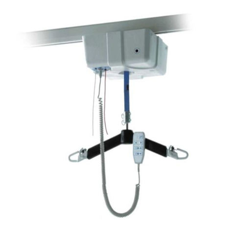
Sunrise Medical Oxford/Hoyer Stature Installation and operation manual

User
Instruction
Manual &
Warranty
Manuel de
l’utilisateur
et garantie
Manual de
Instrucciones y
Garantía para
el Usuario
Oxford®/Hoyer®Stature
Safe working load:
227 kgs / 500 lbs Patient Lift
Benutzerhandbuch
und Garantie
Oxford®/Hoyer®Stature
Zulässige Betriebslast:
227-kg-Patientenlifter
Oxford®/Hoyer®Stature
Charge maximale d’utilisation:
Lève-personne 227kg/500lb
Oxford®/Hoyer®Stature
Carga de trabajo segura:
Elevador para pacientes
de hasta 227 kg

English
294000.10017 Rev. B
2
MANUFACTURER’S CONTACT DETAILS
CONTENTS
1. Oxford/Hoyer Stature Patient Lift............................................................. 3
2. Introduction: About Your Lift .................................................................. 4
3. Assembly and Commissioning Instructions................................................. 5
4. Safety Precautions ................................................................................. 9
5. Operating Instructions............................................................................ 11
6. Removal of 6-Point spreader and 4-Point cradle systems.............................. 15
7. Charging Instructions............................................................................. 17
8. Maintenance Schedule & Daily Check List .................................................. 19
9. Technical Specifications.......................................................................... 22
10. Warranty .............................................................................................. 24
EUROPE
Sunrise Medical Ltd
High Street, Wollaston, Stourbridge,
West Midlands
DY84PS UK
+44 (0) 1384 44 66 22
Fax: +44 (0) 1384 44 66 44
www.sunrisemedical.co.uk
USA
Sunrise Medical, Inc
5001 Joerns Drive
Stevens Point, WI 54481-5040
715-341-3600
800-826-0270 (toll free)
www.sunrisemedical.com

294000.10017 Rev. B
English 3
1. THE OXFORD/HOYER STATURE PATIENT LIFT
READ AND UNDERSTAND THE INSTRUCTIONS IN THIS MANUAL BEFORE
USING YOUR “STATURE”
Boom
Spreader Bar
Motor Gearbox
Mast Extrusion
Rear Castor
(braked)
Push Handle
Foot Push Pad
Straight Line
Steering Device
Battery/
Control Pack
Front Castor
(non-braked)

English
294000.10017 Rev. B
4
2. INTRODUCTION: ABOUT YOUR LIFT
The Oxford/Hoyer Stature is an electrically operated patient lift. Each Stature lift is
fully assembled load tested and certified before being packed/shipped.
The packing consists of a strong, purpose built carton that is used for both export and
domestic markets to ensure the safe arrival of the lift.
A number of documents are supplied in a wallet which is packed with each lift and
should be kept safely for future reference.
• USER MANUAL • CUSTOMER SATISFACTION CARD (Europe only)
• TEST CERTIFICATE • DEALER GUARANTEE CARD (Europe only)
• PACKING CHECK LIST
The TEST CERTIFICATE is an important document and may be required for your insurance
records. It is valid for six months and after it has expired the lift should be inspected
and serviced per the maintenance schedule by a competent authorised engineer.
Servicing and periodic testing can be carried out by your authorised supplier. Please
ensure your lift is included in their maintenance schedule. If you are at all unsure
what your local market servicing requirements are, please check with your dealer
and/or a local government agency.
The Oxford/Hoyer Stature is suitable for the following CATEGORIES of lift within the
working parameters of the lifts specified in the TECHNICAL SPECIFICATIONS (see con-
tents page).
Category A - Wheelchair
Category B - Bed
Category C - Bath (dependent upon setting)
Category D - Toilet/Shower Chair
Category E - Floor
Category F - 90 degree Rotation
The Oxford/Hoyer Stature is suitable for patients in the SITTING, SITTING/RECUMBENT
and RECUMBENT positions. The slings suitable for this device are listed as follows:
• Oxford/Hoyer Quick fit sling • Oxford/Hoyer Full back sling
• Oxford/Hoyer Quick fit deluxe sling • Oxford/Hoyer Long seat sling
• Oxford/Hoyer Access sling • Oxford/Hoyer Four point comfort sling & pad
The CE mark:
The Oxford/Hoyer Stature carries the CE mark and complies
with the following EC directives:
• Medical Device Directive (93/42/EEC)
• EMC Directive (89/336/EEC)
• Low Voltage Directive (73/23/EEC)

English 5
3. ASSEMBLY AND COMMISSIONING INSTRUCTIONS
CARTON CONTENTS
Place the carton in a clear working area and open carefully. The carton contains:
•OXFORD/HOYER STATURE LIFT
•WALLET CONTAINING DOCUMENTS
•HAND CONTROL
•BATTERY PACK
•DESK TOP CHARGER/STAND/LEAD
• FASTENER KIT (INCLUDES SCREWS, ALLEN KEY, HEX SOCKET, CAPPING PLATE)
WARNING
The Oxford/Hoyer Stature is heavy and will need to be lifted with care.
You may need assistance to lift the Oxford/Hoyer Stature from the carton.
ASSEMBLY INSTRUCTIONS
Remove all the parts from the carton and place on the floor, taking care to protect the
finish from damage.
1. Place the chassis and mast (which are connected) in a clear space. The mast and
chassis should be rested on the push handle, which will ensure the product remains
stable while connecting the legs and boom to the product.
294000.10017 Rev. B

English
294000.10017 Rev. B
6
2. Fit the legs to the chassis using two 6mm countersunk screws per leg as provided.
NOTE: There is a left and a right leg and they are configured as shown below
3. Using Allen Key provided, tighten the 6mm screws located on each side of the chassis.
WARNING
The screws should be secured firmly.
4. Insert the curved boom section into the boom carriage. Secure the assembly by
inserting the two 6mm countersunk screws into the blue capping plate provided in
the fastener kit, as shown below and tighten firmly.

294000.10017 Rev. B
English 7
5. Attach four point positioning cradle to the lift boom by inserting the split pin.
Ensure pin is secure.
6. Stand the Stature upright and apply the brakes.
WARNING
Be careful when lifting the Stature to the upright position, as it is heavy.
Fit hand control plug into the bottom of the control box located on the mast, ensure
correct alignment to the plug socket. Fit power pack to the lift and make sure the
latch holding the pack in place is fully engaged “Click” into place.
DISASSEMBLY
The lift should not be disassembled unless for service, repair or transport if necessary.
If disassembly is necessary, follow the assembly instructions in reverse sequence.
2
1

English
294000.10017 Rev. B
8
ALWAYS CHECK THE FOLLOWING BEFORE OPERATION
• Push the open and close buttons on the hand control to confirm that the legs of the
lift open and close satisfactorily.
• The red emergency stop button, located on the rear of the control box, is in the OFF
(out) position.
• Push the up and down buttons on the hand control to confirm that the boom rises
and lowers satisfactorily.

294000.10017 Rev. B
English 9
4. SAFETY PRECAUTIONS
Please read and follow the safety precautions listed below. Following these few basic
safety precautions will make lifting operations easy and trouble free.
• ALWAYS check the safe working load of the lift is suitable for the weight of the patient.
• DO NOT exceed the safe working load of the hoist, as an electrical current limiting
device will activate, preventing use of the hoist.
• ALWAYS plan your lifting operations before commencing.
• ALWAYS carry out the DAILY CHECK LIST before using the lift.
• ALWAYS familiarise yourself with the operating control and safety features of a lift
before lifting a patient.
• DO NOTuse a sling unless it is recommended for use with the lift.
• ALWAYS check the sling is suitable for the particular patient and is of the correct
size and capacity.
• NEVER use a sling which is frayed or damaged.
• ALWAYS fit the sling according to the instructions provided (user instructions).
• ALWAYS ensure sling straps DO NOT get caught around the legs of the hoist.
• ALWAYS carry out lifting operations according to the instructions in the user manual.
• NEVER disconnect or bypass a control or safety feature because it seems easier to
operate the lift.
• DO NOTlift a patient with the castor brakes on. Always let the lift find the correct
centre of gravity.
• DO NOT attempt to manoeuvre the lift by pushing on the mast, boom or patient.
• ALWAYS manoeuvre the lift with the push handle, located on the mast. A foot push
pad is also provided on the base of the hoist.
• ALWAYS lower the patient to the lowest comfortable position before transfers.
• DO NOTpush a loaded lift at speeds which exceed a slow walking pace (3 Km/hour
0.8 metres/second).
• DO NOT push the lift over uneven or rough ground. Particularly if loaded.

English
294000.10017 Rev. B
10
• DO NOT attempt to push/pull a loaded lift over a floor obstruction.
• NEVER force an operating/safety control. All controls are easy to use and do not
require excessive force.
• DO NOT park a loaded lift on ANY sloping surface.
• DO NOT use electric lifts in a shower.
• DO NOT charge an electric lift in a bathroom or shower room.
• DO NOT lift a patient unless you are trained and competent to do so.
• YOUR lift is for patient lifting. DO NOT use it, or allow it to be used, for any other
purpose.
• DO NOT bump the lift down steps, loaded or unloaded.
• DO NOT attempt to negotiate a loaded lift on a slope which exceeds 1:12 (approxi-
mately 5 degrees).
• DO NOTattempt to negotiate a slope without a second helper being present.
• DO NOTuse in a wet or corrosive environment such as poolside locations.
• DO NOT use on extra thick pile carpet when the lift is fully loaded.
• NEVER operate lift with loose/worn or missing parts/fasteners.

294000.10017 Rev. B
English 11
5. OPERATING INSTRUCTIONS
OPERATING CONTROLS
1. Leg adjustment
The legs on the Oxford/Hoyer Stature are electrically adjustable for width. The legs can
be opened to enable access around armchairs or wheelchairs. For transferring and negoti-
ating narrow doorways and passages the lift legs should be in the closed position.
Electric leg adjustment - is achieved by pressing the appropriate buttons on the hand
control. The legs will be locked whenever the hand control switch is released.
2. Castors and Braking
The lift has two braked castors which can be applied for parking. When lifting, the
castors should be left free and un-braked. The lift will then be able to move to the
centre of gravity. If the brakes are applied it is the patient that will swing to the cen-
tre of gravity and this may prove disconcerting and uncomfortable. Attached to the
rear castor is a straight line steering device, which when applied to the castor will
facilitate straight line movement.
3. Raising and lowering the boom
The movement of the boom carriage is achieved by a powerful motor gearbox, which is
controlled by a simple hand control unit. The hand control has two buttons with direc-
tional arrows UP and DOWN áâ. The motor gearbox stops automatically at the limit
of travel in both directions. The hand control plugs into a socket at the base of the
control box. SAFETY NOTE– The downward movement of the boom will stop if the lift
senses that the patient has encountered an obstruction.
Emergency
Stop Button
Hand Control
Battery Indicator
Emergency
Lower/Raise
Detachable Battery
Pack

English
294000.10017 Rev. B
12
4. Emergency Stop
The red Emergency Stop Button is located on the front of the control box and is acti-
vated by pressing in. This will cut all power to the lift and only be reset by twisting
the button anticlockwise and releasing.
5. Electrical Emergency Down/Up
Emergency lower (down) and raise (up) buttons are provided at the front of the control
box. This is operated by inserting a ballpoint pen into the button highlighted áâ.
This will bring the boom up or down should the hand control fail at any time.
6. Mechanical Emergency Down
In the case of a complete electrical failure the Stature lift is fitted with mechanical
lowering device. This device is located on the left hand side of the lift’s chassis.
The lowering mechanism is operated by inserting a 6mm Hex socket into the aperture
and onto the mechanism turning clockwise to raise the lift and anticlockwise to lower
the lift. This can be done manually with a socket wrench.
Recommendation!
In order to raise or lower the boom more quickly it is recommended that a 6mm Hex
socket be used in conjunction with a 1/4 inch drive adaptor and an electric reversible
drill. (Note– do not use hammer setting.) This will increase the speed in which the
patient can be safely raised and lowered. A 6mm Hex socket is contained in the top cap
located on the top of the mast.

294000.10017 Rev. B
English 13
NOTE: Before raising or lowering the patient, ensure you have you have planned your destination
carefully. For instance back onto a chair or bed.
7. Batteries
The batteries are protected from deep discharge by a LOW VOLTAGE ALARM. This will
sound when the batteries need recharging and the hand control is being operated. It
will not sound independently of the hand control being operated. DO NOT IGNORE
THIS WARNING ALARM. Complete the lifting operation and place the battery on
charge (see charging instructions).
8. Slings
The Oxford/Hoyer Stature has the option of both a 6 point spreader bar and a 4 point posi-
tioning cradle. Both systems use different attachment methods and slings.
The 6 point system uses slings with webbing loops, which allow positioning adjustment
by selecting different coloured loops. The 4 point cradle uses the Secruri3 safety clip
system and adjustment is made by rotating the 4 point cradle either upward or down.
Loop strap slings: Oxford/Hoyer Quick Fit, Full back, Quick fit deluxe,
Long Seat and Access slings
Safety clip slings: Oxford/Hoyer Four point comfort sling & pad
The 6 point system attaches to the spreader bar hooks via loop straps (shown below),
each sling is supplied with instructions. Please study the instruction guide before use.
6 Point spreader bar. Example of 6 point spreader bar sling with loop attachments.
Shoulder Straps
Shoulder Strap
Attachment Points
Leg Straps
Leg Strap
Attachment Points

English
294000.10017 Rev. B
14
The four point cradle sling attaches to the cradle studs via a safety clip system (shown
below), each sling is supplied with instructions. Please study the instruction guide
before use
4 point positioning cradle.
Example of 4 point cradle sling with safety clip system.
Securi3 sling attachment system. Example of installation.
Shoulder Straps
Shoulder Strap
Attachment
Point
Shoulder Strap
Attachment
Point
Leg Straps
Leg Strap
Attachment
Points

294000.10017 Rev. B
English 15
6. REMOVAL OF SPREADER BAR/CRADLE SYSTEMS
FOLLOW THESE INSTRUCTIONS EXACTLY
Your Stature lift has the option of using both a 6 point spreader bar and 4 point posi-
tioning cradle. The removal of either of these systems is completed easily by the use
of a quick-release pin. This is done quickly and easily, but you must read the following
safety instructions to ensure the spreader bar/cradle is safely locked into position
before use.
CONNECTION
To connect, raise the spreader bar/cradle up toward the boom slot.
Insert the pin sleeve through the plastic end cap and to support the spreader bar/cradle.
Once aligned in the boom slot reinsert the quick release pin fully into the sleeve until
it locks into position. YOU MUST CHECK THAT THE PIN IS SECURELY FITTED.
To do this, press your finger into the barbed end. If the pin remains stationary the lift
is safe to use.

English
294000.10017 Rev. B
16
REMOVAL
CAUTION: Be sure to support the weight of the spreader bar/cradle before removing pin.
To detach pin, depress the spring barb (using a flat blade electrical screw driver or
similar) and pull the pin out.
Support the spreader bar/cradle, and then pull the pin sleeve in the opposite direction,
removing it completely from the boom. This will release the spreader bar completely.

294000.10017 Rev. B
English 17
7. CHARGING INSTRUCTIONS
The batteries are located in the power pack and are charged via an off board desktop
charger unit.
CHARGING INSTRUCTIONS FOR THE OXFORD/HOYER STATURE
When the power pack needs charging it is removed from the lift and fitted to an off
board charging unit.
Sunrise Medical Ltd recommend an additional battery pack is used, so that one pack
can be on charge at all times.
1. Remove the power pack from the lift. The pack is retained by a simple latch at
the top of the power pack. Lift the latch and the power pack will be released.
2. Fit the power pack to the charging unit. The location and latching of the power
pack to the charger is the same system as used on the lift.
3. Plug the charger mains plug into a suitable mains outlet and switch the mains
supply ON.
4. Charging is automatic and will fully charge the batteries over a period of eight to
twelve hours. Note: Even if the charger is left plugged in for extended periods it
will not allow the batteries to overcharge.
5. To return the lift to service, switch OFF the mains supply and remove the power
pack from the charger. Fit the power pack to the lift and make sure the latch
holding the pack in place is fully engaged. “Click” in place. The charging of
Oxford/Hoyer electric lifts is simple and straightforward, but it is important to
follow the charging instructions closely. Please pay particular attention to the fol-
lowing points, they will help you avoid problems with discharged batteries.
Removable Battery Pack
Control Box
Emergency Stop, Raise/Lower
Hand Control
Legs Open/Close,
Boom Raise/Lower

English
294000.10017 Rev. B
18
WARNING
KEEP the batteries fully charged. Place the battery on charge whenever it is
not in use. If it is more convenient to do so, place on charge every night.
The charger will not allow the batteries to overcharge.
WARNING
NEVER run the batteries completely flat. As soon as the audible warning
sounds, complete the lifting operation in hand and place on charge.
WARNING
NEVER store the power pack for long periods without regular charging
throughout the storage period.
WARNING
ALWAYS make sure the mains power to the charger is switched off before
connecting or disconnecting the power pack.
WARNING
NEVER leave the power pack plugged in to the charger with the mains power off.
WARNING
Do not charge an electric lift in a bathroom or shower room.

294000.10017 Rev. B
English 19
8. MAINTENANCE SCHEDULE & DAILY CHECK LIST
All Oxford/Hoyer products are designed for minimum maintenance, however some safe-
ty checks and procedures are required. A schedule of DAILY tasks is detailed below.
Daily checks and a six monthly service, inspection and test will ensure a lift is kept in
optimum safe working condition. A list of spare parts is available upon request.
The LOAD TEST and certification should only be carried out by qualified personnel or
an authorised service agent / dealer.
DAILY CHECK LIST: Sunrise Medical strongly recommends the following checks be
carried out on a daily basis and before using lift.
• MAKE sure the lift moves freely on its castors.
• MAKE sure the spreader bar is free to rotate and swing
• EXAMINE the spreader bar/cradle is firmly attached to the boom.
• EXAMINE the sling hooks/clips on the spreader bar/cradle and side suspenders for
excessive wear.
• MAKE sure the legs open and close correctly.
•OPERATE the hand control to confirm the boom raises and lowers satisfactorily.
• ON electric powered lifts check the operation of the emergency stop button.
•EXAMINE slings for fraying or other damage. DO NOT use any sling if damaged or
if the sling shows signs of wear.
• CONFIRM the lift is not giving a low battery alarm when the hand control is oper-
ated. If the alarm sounds, DO NOT use, and place on charge immediately.
• CHECK fasteners for tightness and wear.
MAINTENANCE, INSPECTION AND TEST
Sunrise Medical recommend a thorough inspection and test of the Oxford/Hoyer
Stature lift and lifting accessories, slings, scales etc is carried out on a regular basis.
Inspection frequency varies from country to country so you must check with your deal-
er or local government agency how often an inspection is required. The examination
and test should be conducted according to the recommendations and procedures
below. Sunrise Medical recommends maintenance, inspection and certified testing is
carried out by authorised service agent / dealers only.
NOTE– These recommendations are in compliance with the requirements of 1998 No2307 Health
and Safety: The Lifting Operations and Lifting Equipment Regulations 1998. This is a UK
regulation. Outside the UK please check your local country requirement.

English
294000.10017 Rev. B
20
1. SPREADER BAR: Check the spreader bar for freedom of rotation 33
and swing. Check for wear on the central pivot. Check for firm
attachment to the boom.
2. BOOM: Check the attachment of the boom to the mast carriage. 33
Make sure there is only minimal movement.
3. MAST: Check it is firmly connected to the chassis. 33
4. MOTOR GEARBOX: This should require no maintenance other than 3
checking for correct operation and listening for unusual noise.
5. POWER PACK: Check the function of the emergency stop button 33
and emergency down/up.
6. BATTERIES: The batteries are housed in the power pack and should
3
not require maintenance other than the regular charging as
detailed in the charging instructions. Check that the connections
remain clean. Confirm the battery bracket is secure and undamaged.
7. LEG ADJUSTMENT: Check that the legs operate in both full 3 3
extensions (inward/outward).
8. CASTORS: Check all castors for firm attachment to the legs. 33
Check for free rotation of the castor and the wheels.
9. CLEANING: Wipe down with a clean cloth, using soap and water
3
and/or any hard surface disinfectant. Harsh chemical cleaners or
abrasives should be avoided as these may damage the surface
finish of the lift. Avoid excessive wetting, especially electrical
areas and the opening to the base of the hoist. We recommend
that the cloth is soaked in the solution, squeeze out excess fluid
and wipe hoist surface.
10. LOAD TEST: The load test should be carried out in accordance
with the manufacturer's test procedures (see Service Manual).
3
It is strongly recommended the testing is carried out by an
authorised service dealer.
11. BASE AND WHEELS: Ensure base is even and level 33
(all four wheels are on the floor).
12. SLINGS: Check for wear and fraying. 3
13. LUBRICATION: Oil pivot joints, including mast and boom 3
connections, pedal assembly, spreader bar joint (only if required).
14. HAND SET:Ensure plugged fully into controller. 33
*THESE CHECKS SHOULD INCLUDE:
Before Use
Initially
Service
Intervals
Table of contents
Languages:
Other Sunrise Medical Lifting System manuals